Study for Femto Satellites Using Micro Control Moment
Gyroscope
Mark Post
Space Mechatronic Systems Technology Laboratory
Department of Design, Manufacture and Engineering Management, University of Strathclyde Glasgow, United Kingdom
Ralf Bauer
Centre for Microsystems Photonics
Department of Electronic Electrical Engineering, University of Strathclyde Glasgow, United Kingdom
Junquan Li Clyde Space Ltd Glasgow, United Kingdom [email protected]
Regina Lee
Department of Earth and Space Science and Engineering, York University Toronto, Canada
Abstract—Femto-satellites can be used for distributed space missions that can require hundreds to thousands of satellites for real time, distributed, multi-point networks to accomplish remote sensing and science objectives. While suitable sensors are available using micro-electro-mechanical system technology, most femto-satellite designs have no attitude control capability due to the power and size constraints on attitude control actu-ators. A novel femto-satellite design that uses a micro-electro-mechanical system Control Moment Gyroscope is studied in this paper. We focus on the principal design, modelling, and discussion of the proposed Control Moment Gyroscope while detailing a controllable femto-satellite design that can make use of attitude control for simple sensing missions.
TABLE OF
CONTENTS
1 INTRODUCTION. . . 1
2 PROPOSEDFEMTO-SATELLITESYSTEMDESIGN 2 3 PROPOSEDMEMS CMG DESIGN . . . 3
4 SIMULATIONRESULTS ANDDISCUSSION. . . 5
5 CONCLUSIONS. . . 6
ACKNOWLEDGMENTS . . . 6
REFERENCES . . . 6
BIOGRAPHY . . . 7
1. INTRODUCTION
A distributed space system is a system of multiple spacecraft designed to work in a coordinated group to perform a mission, such as communications, navigation, remote sensing, space exploration and science. A distributed spacecraft system using femto-satellites can provide significant flexibility and robustness compared to a large satellite [1]. Due to the mass, size and power constraints of femto-satellites, very few Attitude and Orbit Control System (AOCS) options are available [2], and the tolerances of micro AOCS systems can be very limited. Next generation sensors for femto-satellites have been studied for use in disaster management missions [3]. Femto-satellites can be based on CMOS (Complemen-tary Metal-Oxide Semiconductor) and MEMS (Micro Electro
978-1-4799-5380-6/15/$31.00c2015 IEEE.
Mechanical System) technologies [4], but few active control systems have been proposed for femto-satellites. The Control Moment Gyroscope is a space attitude control actuator which acts as torque amplifier [15]. It is more efficient than a reaction wheel in terms of power consumption and slew rate [16]. A MEMS control moment gyroscope for a sub kilogram spacecraft has been studied [17], but no feasibility study for such a MEMS CMG for femto-satellites has been done. The power requirements, thermal design, and performance capabilities of MEMS actuator systems are heavily dependent on environmental variables such as temperature variation, and study of the on-orbit operational requirements for a femto-satellite is a vital part of the design process. We propose the use of a MEMS CMG and conduct a feasibility study for a femto-satellite attitude control system in this paper to illustrate the potential capabilities and key challenges for such a mission.
Femto Satellite Survey
ground stations or other femto-satellite in the swarm must be increased.
Control Moment Gyroscope Survey
Future science and exploration missions will strongly rely on innovative Guidance Navigation and Control (GNC) tech-nologies. The CMG has been also used for space robotics, underwater vehicles, and on the International Space Station as well as for other large space missions [13] and[14], but Control Moment Gyroscopes are not often considered for use on small satellites [9], [10], [11] and [12]. The main reasons are due to the complexity of the mechanical and control system needed to implement an effective CMG. CMG systems have many advantages over reaction wheels and magnetic rods, such as a large torque amplification capability, large moment storage capability, and high angular agility. By applying advances in computer aided design tools and electronics technologies, CMG systems have more recently been considered for small satellites [15] and [16]. It also has been considered for femto-satellites [17] and [18]. The main challenges with the creation of a MEMS CMG are the silicon micro machining technology and the control system [23].
MEMS Actuator Survey
The future science and exploration missions will be critically dependent on the development, validation and infusion of micro-electro-mechanical systems (MEMS) based spacecraft guidance navigation and control avionics they are highly in-tegrated, power efficient, and minimally packaged which can be flexible to meet specific mission requirements [19], [20], [21], [22] and [23]. For MEMS actuators, some additional considerations should be included in order to get the best functionality, such as pull-in-instability and high Q factors. [24]. The space environment poses many environmental haz-ards, and not all materials are suitable for that environment. Electronic components can exhibit unpredictable behaviours without shielding, thermal gradients are wide, and the tem-perature changes fast and beyond the usual ranges inside the atmosphere. MEMS sensors and actuator functionality have to be tested with thermal, vibration and radiation testing [25] and [26] before being used for femto-satellite missions.
2. PROPOSED
FEMTO-SATELLITE
SYSTEM
DESIGN
Figures 1 and 2 show a high-level concept design for the proposed femto-satellite and its power and actuator drive sys-tems. The proposed femto-satellite has three surfaces joined at right angles in a half-cube configuration. Each surface covers the outer side of the half-cube with solar panels and is intended to remain sun-pointing by attitude control assisted by solar radiation pressure. The inner side holds the electrical power system, battery, data handling microcontroller (On-Board Computer), watchdog timer, communication system (radio and transceiver), attitude and orbit determination and control system, thermal system, and a selected payload (con-sidered to be a CMOS imager) [2].
A dedicated electronic controller and high-voltage drive circuit is necessary for micro-electro-mechanical system (MEMS) electrostatic actuators. Different MEMS actuators have specific requirements for their power supplies (10−
[image:2.612.317.563.54.194.2]300v), activation current (1µA to 5mA) and commutation speed [27]. The controller of the proposed MEMS CMG will initially be based on a programmable micro-controller core and in more developed versions, Field-Programmable Gate
[image:2.612.315.559.232.473.2]Figure 1. Femto-Satellite Structure with MEMS CMG
Figure 2. Power and Drive System Design for Femto-satellite with MEMS CMG
Figure 3. Principle of CMG.
3. PROPOSED
MEMS CMG DESIGN
CMG Principle
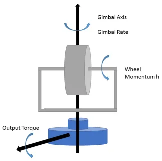
The working principle of the MEMS CMG is similar to a single gimbal CMG (shown in Figure 3). In order to get the equations of the torque output, two reference frames, gimbal reference frame (xg,ygandzg) and substrate reference frame (xs, ys andzs) are defined. When the gimbal angles are zero, the two frames coincide with each other. The spinning rotor is assumed as a rigid body which is symmetric about the spinning axiszg in the gimbal frame. The rotor rotates with an angular velocityω. Therefore the angular momentum of the rotor in the substrate frame is defined as
h=J ω (1)
whereJis the inertial moment of the spinning rotor aboutzg.
The gimbal rate is defined asD˙δ. The CMG output torque is perpendicular to the directions ofωandD˙δ.
T =hD˙δ (2)
In the proposed MEMS CMG, the angular sinusoidal vi-brations substitute for the angular rotations. The angular displacements of the rotor and gimbal can be written as
Dr=Arsin(2πf t) (3)
Dδ =Agsin(2πf t) (4)
where Ar and Ag are the angular vibration amplitude of the rotor and the gimbal, respectively, andf is the resonant frequency of the rotor and gimbal. The angular velocities of the rotor and gimbal can be written as
ω= 2πf Arcos(2πf t) (5)
˙
Dδ = 2πf Agcos(2πf t) (6)
Substituting Equations 1-6, the output torque can be written as
T =J(2πf)2ArAgcos2(2πf t) (7)
Rotation comb-drives A Rotation comb-drives B Rotation comb-drives A
Rotation comb-drives B
Tilt comb-drives
[image:3.612.320.551.55.204.2]Substrate connection
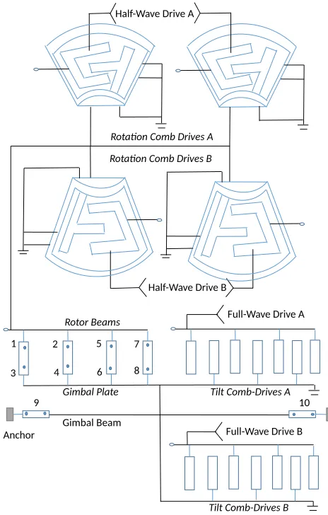
Figure 4. Proposed design for the single device layer MEMS CMG, showing the moving parts of the CMG and highlight-ing the comb-drive actuators which would require the three different drive signals to create the combined rotational and tilt oscillation for creating the torque output of the CMG.
The amplitude of the MEMS CMG output torque is propor-tional to the inertial moment of the spinning rotor, resonant frequency and the amplitude of vibration.
Design of MEMS CMG
The design of the proposed MEMS CMG is influenced by a targeted fabrication possibility using a cost-effective and reliable multi-user single crystal silicon-on-insulator (SOI) process. The proposed design consists of a single device layer and is based on a rotational oscillation of a disk which is coupled to a frame with a tilt oscillation about its main axis. This main axis is defined by the substrate connections of the fully released moving structure. Both the rotational and the tilt oscillation are coupled by using resonance movement modes of the same frequency. This, combined with the choice of an appropriate phase relationship between the two movements, allows for the generation of a uni-directional torque which can be reversed by applying a180◦phase shift between the electrical actuation signals of both movements.
The actuation principle of the proposed MEMS CMG is based on the use of capacitive electrostatic comb-drives for both movement modes. Electrostatic actuation exhibits general advantages of lower power consumption compared to other MEMS actuation mechanisms, with the specific case of comb-drive actuators reducing the risk of pull-in phenomena and requiring in general less actuation voltages compared to backside electrode actuators. Additionally, rotational comb-drive actuated tilt devices have shown the ability to generate tilt angles of 80◦ for 8−10kHz movements [32] even in atmospheric pressure conditions. The single device layer employed by the proposed use of a multi-user process allows for easy comb alignment without the necessity to employ ad-ditional wafer bonding or other functional parts, as would be the case for electromagnetic actuation or backside capacitive electrodes.
the rotation force for each direction of rotation. Comb-drives A allow in this case for a clock-wise actuation, with comb-drives B being responsible for the counter-clockwise actuation. The design limits the maximum rotation angle of the oscillation to ±9◦. The 55µm wide outer frame anchors the fixed combs of the rotational comb-drives, the moving combs for the tilt movement and the connection to the torsional spring connection to the silicon substrate. Not shown in the schematic of Figure 4 is the necessary isolation between the fixed rotation comb-drives and the rest of the structure. This can be done using an additional fabrication process step or through a post-process coating step creating a solid connection between physically separated parts of the MEMS CMG structure.
The proposed CMG design was chosen with the use of a multi-user fabrication process in mind. This will allow the use of a cost-effective and well established process which will allow quick turn around with proven process stability. The envisaged multi-user fabrication process is the single crystal silicon-on-insulator fabrication process SOIMUMPs offered by Memscap Inc. [28]. The process is based on a phosphors doped, 25µm SOI device layer, using a single etch step of this device layer to create the functional device parts and a further backside etch step to fully release the functional parts from a400µm thick silicon handle waver. The doped device layer will allow for electrical connectivity of the actuators. Each fabricated MEMS chip consists of a9×9mm2design area which would allow for the creation of an array of 9-12 synchronized MEMS CMG’s per chip.
Figure 5 shows the system model of the MEMS CMG. As shown in Figure 2, the power electronics for the MEMS CMG are designed around a simple frequency generator, which drives both the rotation and gimbal tilt of the CMG synchronously. The comb drive used for tilting the gimbal plate of the CMG around two twisting beams causes the movable combs to vibrate about the horizontal, where the outer combs are placed. Therefore, at a given frequency both the positive and negative parts of the full-wave cycle can be used for the tilt combs. The rotating wheel of the CMG is actuated by a push-pull arrangement of combs, and constrained to the plane of vibration by four rotor beams. The two sets of rotation combs are driven alternately, so half-wave rectifiers are used to split the positive and negative parts of the cycle. Separate voltage ladders are then used to raise the voltage for each of the four drive outputs on the power circuit, which are connected through a high-voltage interface on the MEMS die.
Rotor Calculation of MEMS CMG
If the comb-drive is actuated by a single-sided voltage, the force exerted by each movable comb finger ([29]) can be approximated by
F =hV
2
g (8)
The total torque generated by the entire rotary comb-drive is given by
T =hV
2
g N R (9)
[image:4.612.322.554.56.420.2]Nis the number of comb fingers,Ris the radius of each comb finger,is the permittivity of the single crystal silicon device-layer, h is the high of the comb fingers, V is the voltage difference between the moving combs and the fixed combs, andgis the horizontal distance between the comb fingers.
Figure 5. System Level Model of MEMS CMG.
Gimbal Calculation of MEMS CMG
The movement of the gimbal is created by applying a single-or dual-sided voltage signal to the comb-drive electrodes located on the substrate of the MEMS chip. This resonant movement is governed by the equation of motion for a forced oscillator, with the drive force of the oscillator being given by:
F = 1
2V
2(t)∂C
∂θ (10)
whereCis the capacitance of the gimbal comb-drive andθis the tilt angle of the gimbal around its major axis.
4. SIMULATION
RESULTS AND
DISCUSSION
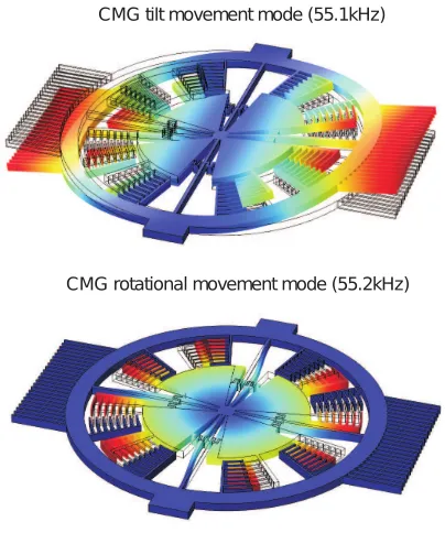
For the electro-mechanical simulation of the MEMS CMG the finite element modelling (FEM) software COMSOL Mul-tiphysics is used, looking at the mechanical resonance eigen-frequencies of the proposed CMG and later on toward a full electromechanical simulation. The material properties of the single crystal silicon of the envisaged SOIMUMPs process have been investigated before [31], with their anisotropic parameters being used as basis for the FEM simulation. The first two mechanical oscillation eigenmodes of the proposed MEMS CMG are shown in Figure 6, depicting the tilt move-ment around the major axis of the device at 55.1kHz and the rotation movement of the inner disk at 55.2kHz. By synchronizing both movements through appropriate electrical actuation signal control the combined movement would result in the synchronous switching of both the rotation and tilt movement directions, therefore creating a resulting torque in a single direction.
CMG tilt movement mode (55.1kHz)
[image:5.612.70.272.244.486.2]CMG rotational movement mode (55.2kHz)
Figure 6. Simulated eigenmode shapes of the proposed MEMS CMG, showing the rotational oscillation at55.2kHz and the tilt oscillation at55.1kHz.
To estimate the potential torque that can be generated by the MEMS CMG, equation 7 is used with the design parameters of the proposed device. The mass moment of inertiaJfor the rotating part of the CMG is calculated as4.7·10−16m2kg, using the same FEM simulation as for the simulation of the device resonance frequencies, with the frequency f of both the rotation and tilt movements being 55kHz. For an assumed rotation amplitude of9◦and a tilt amplitude of10◦ this leads to a maximum torque for a single MEMS device approximated as1.5·10−6Nm. This maximum torque occurs during the centre crossing of the synchronized rotational and tilt oscillation. This torque is almost2orders of magnitude higher than the value estimated by [17], which can be mainly attributed to the increase in the oscillation frequency for the here proposed design.
Discussion of Thermal Effects
As the MEMS CMG has not yet been fabricated, definite testing of its thermal and radiation characteristics at this stage is not possible. In particular, radiation testing is very
time-consuming and costly due to the facilities required. However, we can attempt to estimate its performance and limitations based on prior work that has been done on similar comb-drive devices.
The main influence that temperature is expected to have on the MEMS CMG is the temperature dependent Youngs modulus of Silicon, which determines the resonance charac-teristics of the CMG. Many commercial MEMS comb-drive devices can tolerate the approximately −65oC to 120oC temperature range in low Earth orbit without critical failure, and the highest chance of failure in MEMS devices is due instead to launch vibration [37], the accuracy of operation of the device often suffers. Temperature sensitivity on the resonant frequency is in the range of 31ppm/oC close to room temperature [31], but over a temperature variation on the order of100oC, this can often be up to the range of1%of the resonance frequency. The CMG is intended to be driven synchronously as close to its resonance frequency as possible to minimize the effect of changes in the high Q factor of the comb drive with temperature [35], but this requires that the resonance frequency be either constrained or tracked.
One way to reduce temperature influences on resonant MEMS structures is to use highly-doped Silicon for the struc-ture, as heavy doping can change the temperature dependence of elastic constants in silicon by on the order of100ppm/oC [33]. This approach can also cause residual stresses and other unwanted effects in the semiconductor though, and needs further research before becoming a viable option. It is also possible to adapt the design dimensions of a MEMS device by means of a simulation optimization loop so that a flat capacitance response with temperature is generated as used by Liu et al. [34], but a significant amount of design and optimization effort is needed, and further simulation work is needed to evaluate the feasibility of this approach for the proposed MEMS CMG layout.
Active temperature compensation has also been developed for MEMS devices. Prikhodko, Trusov, and Shkel propose self-referencing of the temperature for compensation of a MEMS Quadruple Mass Gyroscope through accurate sensing of the drive-mode resonance frequency with a phase-locked loop that monitors frequency shifts relative to a high-stability frequency reference [36]. For a high Q-factor system such as this, a10ppbfrequency resolution was possible near room temperature, and reduction of temperature-induced drift from approximately500o/hrto under2o/hr. Even trading off the high precision of measurement of this system for a wider temperature range compensation, we expect that a similar compensation system can be used to accurately track changes in CMG resonance and allow the CMG to continue operation across low Earth orbit temperature ranges.
Discussion of Radiation Effects
likely to affect MEMS devices.
Ionization damage can have a major impact on the function of low-voltage VLSI MOS ICs, and can cause failure of electrostatically-actuated devices through trapped charge in the structure. The potential of trapped charge to affect MEMS devices is significant, but depends on the layout and actuation voltage of the device, as several comb-drive devices have exhibited changes in dielectric charging of the device up to50krad of proton radiation but no permanent functional damage, and a conducting polysilicon film was shown to prevent such degradation up to3M rad[39]. Several years in low earth orbit would be needed before appreciable changes would be observed, and greater care would be needed in the design of the drive and control circuitry than the MEMS gyro itself.
Lozano, Palumbo and Alurralde describe a MEMS micro-relay device with a20µmthick single crystal silicon layer, thirty 3µmwidth and3µmgap comb drive fingers, and an activation voltage from 22V-50V [40]. When exposed to a
10M eV proton beam, capacitance between the contact pad of the comb drive and the P-type silicon changed only on the order of0.05%with total doses between1.7e9p+/cm2 and 3.5e11p +/cm2, and at constant capacitance a shift in voltage of approximately −4.5V. This did not cause a significant variation in a nominal activation voltage of 23V, the level of leakage current between the pads of the structure, and the conduction resistance of the device before and after irradiation. Although it is expected that the shift in voltage at constant capacitance will change the activation voltage to some degree, the observations are that very little shift is present. Given the relatively high voltages required to drive the CMG, this shift is not expected to significantly impact performance.
5. CONCLUSIONS
We have discussed in this paper a feasible femto-satellite design featuring attitude control that makes use of a MEMS-based attitude determination and control system. While small, this femto-satellite contains all the fundamental com-ponents for a controllable satellite, and can be capable of for-mation flying and simple measurements. The MEMS CMG is designed both for efficient operation, and for reliable and cost-effective fabrication using multi-user processes. Future work will include more detailed design and simulation for both the MEMS CMG and femto-satellite model, which will culminate in the fabrication of a functioning MEMS CMG system.
ACKNOWLEDGMENTS
The authors would like to thank Prof. Deepak Uttamchandani at the University of Strathclyde for his assistance with this research.
REFERENCES
[1] Fred Y. Hadegh, Soon-Jo Chung and Harish M. Manohara, ”On Development of 100 Gram Class Space-craft for Swarm Applications”, IEEE System Journal, Vol. 99, No. 99, 2014.
[2] David J. Barnhart, Tanya Vladimirova, Adam M Baker, Martin, N Sweeting, ”A Low Cost Femtosatellite to
Enable Distributed Space Missions”, Acta Astronautica, Vol. 64, pp 1123-1143, 2009.
[3] Luis Izquierdo, Joshua Tristancho, ”Next Generation of Sensors for Femto Satellite Based on Commercial of the Shelf”, IEEE/AIAA, Digital Avionics System Conference, 2011.
[4] Nizar Tahri, Chaffa Hamrouni, Adel M. Alimi, ”Study of Current Femto Satellite Approaches and Services”, International Journal of Advanced Computer Science and Applications, Vol. 4, No. 5, 2013.
[5] P. R. Sundaramoorthy, E. Gill, and C. J. M. Verhoeven, ”Systematic Identification of Applications for a Cluster of Femto-satellites”, 61th International Astronautical Congress, Prague, CZ,2010, pp 1-5.
[6] Geoffrey. R. McVittie. and Krishna Dev Kumar, ”De-sign of a COTS Femtosatellite and Mission”, AIAA Space 2007 Conference and Exposition.
[7] Joshua Tristancho, ”Implementation of a Femto-satellite and a Mini-launcher”, Msc Thesis, University of Polytechnic de Catalunya, 2010.
[8] Enric Fernandez-Murcia, Luis Izquierdo and Joshua Trishtancho, ”A Synthetic Aperture Antenna for Femto-satellites based on Commercial-of-the-shelf”, IEEE 2011.
[9] A. R. Morse, ”MSFC Skylab Apollo Telescope Mount”, NASA Technical Memorandum, NASA TM X-64811, 1974.
[10] Lyndo, B., ”Lessions Learned on the Skylab Program”, NASA Technical Memorandum, NASA TM X-72920, 1974.
[11] Roser, X., and Sghedoni, M., ”Control Moment Gy-roscopes and Their Application in Future Scientific Missions”, Proceeding 3rd International Conference on Spacecraft Guidance, Navigation and Control Systems, 1997, pp 523-528.
[12] Defindini, A., Faucheux, P., Guay, P., Bangert, K., Heimel, H., Privat, M., and Seiler, R., ”Control Moment Gyro CMG 15-45s: A Compact CMG Product for Agile Satellites in the One Ton Class”, Proceeding of the 10th European Space Mechanisms and Tribology Symposium, 2003, pp 27-31.
[13] Peck, M. A., Paluszek, M. A., Thomas, S. J. and Mueller, J. B., ”Control Moment Gyroscopes for Joint Actuation: A New Paradigm in Space Robotics”, AIAA 1st Space Exploration Conference: Continuing Voyage Discovery, 2005, pp 2005-2522.
[14] Thornton, B., Ura, T., and Nose, Y., ”Combined En-ergy Storage and Three Axis Attitude Control of a Gyroscopically Actuated AUV”, Proceeding of Oceans MTS/IEEE, 2008, pp 1-9.
[15] Craig Clark, Kevin Worral, Emre Yavuzoglu, ”A Con-trol Moment Gyro for Dynamic Attitude ConCon-trol of Small Satellites”, 24th Annual AIAA/USU Conference on Small Satellite Conference 2010, SSC10-XI-8,
[16] Mohammed Arezki Si Mohammed, ”Simulation of Three Axis Attitude Control using a Control Momentum Gyroscope for Small Satellites”, Proccedings of the World Congress on Engineering 2012, Vol II, WCD 2013, July 4-6, 2012, London, UK.
MEMS Control Moment Gyroscope for the sub kilo-gram Spacecraft”, Sensor, Vol. 10, pp 4130-4144, 2010. [18] Joel Reiter, Karl Bohringer and Mark Campbell, ”MEMS Control Moment Gyroscope Design and Wafter-based Spacecraft Chassis Study”, In Proceed-ings of the SPIE Conference on Micromachined De-vices and Components, Santa Clara, CA, USA, Septem-ber 20-21, 1999, pp 122-128.
[19] D. J. Bell, T. J. Lu, N. A. Fleck, and S. M. Spearing, ”MEMS Actuators and Sensors: Observations on their Performance and Selection for Purpose”, Journal of Micromechanics and Microengineering, Vol. 15, 2005, pp 153-164.
[20] Y. L. Kuo, K. D. Kumar, K. Behdinan, and Z. Fawaz, ” Attitude Control of Miniature Spacecraft using MEMS Actutors”, In Proceeding of Canadian Conferece on Electrical and Computer Engieering, Ottawa, ON, Canada, April 22-26, 2007, pp 160-163.
[21] D. J. Barnhart, ”Very Small Satellite Design for Dis-tributed Space Missions”, Journal of Spacecraft and Rockets, 2007, Vol. 44, pp 1294-1396.
[22] W. C. Tang, ”Micromechanical Devices at JPL for Space Exploration”, IEEE Aerospace Conference, Snowmass at Aspen, CO, USA, March 21-28, 1998. [23] Tony, K. Tang, Roman, C. Gutierrez, Christopher, B.
Stell, Vatche Vorperian, Genji, A. Arakaki, John, Rice, Wen, J. Li, Indrani, Chakraborty, Kirill Sheheglov, Jaroslava, Z. Wileox, ”A Packaged Silicon MEMS Vi-bratory Gyroscpe For Microspacecraft”, Micro Electro Mechanical Systems, IEEE 10th Annual Internaitonal Workshop, Hotel Nagoya Castle, Japan, 1997.
[24] Wen-Ming Zhang, Han Yan, Zhi-ke Peng and Guang Meng, ”Electrostatic Pull-in Instability in MEMS/NEMS: A Review”, Sensors and Actuators A: Physical, 2014, pp 187-218.
[25] Gary, K. Maki and Pen-shu Yeh, ”Radiation Tolerant Ultra Power CMOS Microelectronics Technology De-velopment Status”, NASA Earth Science Technology Conference 2003, June 24-26, University of Maryland Inn and Conference Center.
[26] Joel Gambino and Neil Dennehy, ”A Multi Func-tion Guidance, Navigatin and Control System for Fu-ture Earth and Space Science Missions”, 25th Annual AAS Guidance and Control Conference, February 6-10, 2002, Breackenridge, Colorado.
[27] Jean-Francois Saheb, Jean-Francois Richard, R. Mein-gan, M. Sawan, and Y. Savaria, ”System Integration of High Voltage Electrostatic MEMS Actuators”, IEEE 2005.
[28] Memscap Inc., Research Triangle Park, NC, USA. 12 Alexander Drive, Building 100. [Online]. Available: http://www.memscapinc.com
[29] J. Andrew Yeh, Chi-Nung Chen, and Yen-Seng Lui, ”Large Rotation Actuated by in plane Rotary Comb-drives with Serpentine Spring Suspension”, Journal of Micro-mechanics and Microengineering, Vol. 15, 2005, pp 201-206.
[30] Honglong Chang, Bin Bai, Wenlong Jiao, and Jianbing Xie, ”Design of a Micro Control Moment Gyroscope with a Large Torque Output” (in Chinese), Chinese Journal of Sensors and Actuators, Vol. 24, No. 8, 2011. [31] M. A. Hopcroft, W. D. Nix, and T. W. Kenny, ”What is the Young’s Modulus of Silicon?”, IEEE Journal of
Microelectromechanical Systems, 2010, vol. 19, pp. 229-238.
[32] R. Bauer, A. Paterson, C. Clark, D. Uttamchandani, and W. Lubeigt, ”Output Characteristics of Q-switched Solid-State Lasers Using Intracavity MEMS Micromir-rors”, IEEE Journal of Selected Topics in Quantum Electronics, 2015, vol. 21, pp. 356-363.
[33] Eldwin Jiaqiang Ng, Vu Hong, Yi Yang, Chong H. Ahn, Camille LM Everhart, and Thomas W. Kenny, ”Temperature Dependence of the Elastic Constants of Doped Silicon,” in Journal of Microelectromechanical Systems, vol.24, no.3, June 2015, pp.730-741
[34] Guangjun Liu, Feng Yang, Xiaofan Bao, and Tao Jiang. ”Robust Optimization of a MEMS Accelerometer Con-sidering Temperature Variations.” Sensors 15, no. 3, 2015, pp 6342-6359.
[35] Shirin Ghaffari, Eldwin Jiaqing Ng, Chae Hyuck Ahn, Yushi Yang, Shasha Wang, Vu A. Hong, and Thomas W. Kenny, ”Accurate Modeling of Quality Factor Behavior of Complex Silicon MEMS Resonators”, Journal of Microelectromechanical Systems, Vol. 24, No.2, 2015, pp 276-288.
[36] Igor P. Prikhodko, Alexander A. Trusov and Andrei M. Shkel, ”Compensation of Drifts in High Q MEMS Gyroscopes using Temperature Self-sensing”, Sensors and Actuators A: Physical, Vol 201, 2013, pp 517-524.
[37] T. F. Tan and K. Weber and C. K. H. Dharan, ”Fail-ure Analysis of Thermal Actuators, Comb Drives, and Other Microelectromechanical Elements”, Journal of Failure Analysis and Prevention, April 2007, Vol. 7, No. 2, pp 137-143.
[38] Herbert R. Shea, “Reliability of MEMS for space appli-cations”, in “Moems-mems 2006 micro and nanofabri-cation”, International Society for Optics and Photonics, 2006, pp 61110A–61110A.
[39] Herbert R. Shea, “Effects of radiation on MEMS”, in “SPIE MOEMS-MEMS”, International Society for Optics and Photonics, 2011, pp 79280E–79280E.
[40] A. Lozano and F. Palumbo and F. Alurralde, ”Radiation Effects on SOI Electrostatic Comb Drive Actuators of MEMS Devices”, Proceedings of the Argentine School of Micro-Nanoelectronics, Technology and Applica-tions, 2009, pp 46-49.
BIOGRAPHY
[
Ralf Bauerreceived his Dipl.-Ing. de-gree in Mechatronics from the Univer-sity of Erlangen-Nuernberg, Germany in 2010 and his Ph.D. degree in the Department of Electronic and Electri-cal Engineering from the University of Strathclyde, U.K. in 2013. He is cur-rently a Research Associate at the Uni-versity of Strathclyde in the United King-dom. His research interests are MEMS enabled miniaturisation of biomedical devices, optical sen-sors and laser systems.
Junquan Li received her M.sc. from the University of Science and Technol-ogy Beijing, China in 2006 and Ph.D. in Department of Aerospace Engineer-ing from Ryerson University, Canada in 2012. She was a MITACS PDF fellow in Canada during 2012-2013. She is a Marie-Curie PDF researcher at Astronet II FP7 networks in the United Kingdom from 2014-2015. Her research areas are attitude and orbit determination and control, nanosatellite and CubeSat engineering, formation flying, and fault tolerant control theory and applications.