City, University of London Institutional Repository
Citation
:
Ozkaya, M. and Kloukinas, C. (2013). Towards Design-by-Contract based
software architecture design. Paper presented at the 2013 IEEE 12th International
Conference on Intelligent Software Methodologies, Tools and Techniques (SoMeT), 22nd
September - 24 September 2013, Budapest, Hungary.
This is the unspecified version of the paper.
This version of the publication may differ from the final published
version.
Permanent repository link:
http://openaccess.city.ac.uk/3582/
Link to published version
:
Copyright and reuse:
City Research Online aims to make research
outputs of City, University of London available to a wider audience.
Copyright and Moral Rights remain with the author(s) and/or copyright
holders. URLs from City Research Online may be freely distributed and
linked to.
City Research Online:
http://openaccess.city.ac.uk/
[email protected]
Towards Design-by-Contract Based Software
Architecture Design
Mert Ozkaya
Department of Computer Science City University London London, EC1V 0HB, UK Email: [email protected]
Christos Kloukinas
Department of Computer Science City University London London, EC1V 0HB, UK Email: [email protected]
Abstract—Design-by-Contract (DbC) gained wide familiarity
among software developers for specifying software. It aids in documenting the behaviour of class methods as contracts between clients of the methods (pre-) and their suppliers (post-condition). This not only allows developers to document software behaviour precisely at such a high-level that can more easily be communi-cated, but also enables the formal verification of the behaviour.
In this paper, we provide a comprehensive extension to DbC so that it can also be applied to the level of software architecture design. We illustrate this through our architecture description language XCD. Components in XCD have four different types of interfaces: provided and required interfaces of methods or emitter and consumer interfaces of events where methods/events are contractually specified. Contract specification is separated into functional and interaction contracts thus modularising the functional and interaction component behaviours. Furthermore, treating interaction protocols as connectors, XCD allows to specify connectors with interaction contracts that participating components adhere to.
The formal semantics of XCD are defined using Finite State Process (FSP) thus enabling formal analysis of contractually spec-ified software architectures for quality properties, e.g., deadlock.
I. INTRODUCTION
Since early nineties, several architecture description lan-guages (ADLs) have been developed, e.g., Darwin [15], Uni-Con [27], Wright [2], LEDA [7], Koala [29], SOFA [25], and CONNECT [12]. They allow designers to specify architectures of large and complex systems. Some (Koala and UniCon) place their focus on automatic code generation, and some (Darwin, Wright, LEDA, SOFA, and CONNECT) on formal analysis of software architectures. Those addressing formal analysis mostly adopt process algebras (e.g., FSP [16] by Darwin and CONNECT, CSP [11] by Wright or π-calculus [22] by LEDA) in specifying the behaviour of software architectures. The process algebras provide formally defined, mathematical syntax and semantics leading to formal specifications which can be rigorously analysed through model checker tools. However, the syntax of process algebras looks unfamiliar to the practising designers who might find it hard to specify their systems as parallel composition of processes [1]. Indeed, a recent survey about architecture description languages [18] states that process algebraic ADLs result in steep learning curve which would make designers invest considerable amount of effort and time to learn and use the algebraic notations. Therefore, formal analysis of software architectures goes far beyond the capabilities of designers, instead requiring expert-level knowledge of process algebras.
Algebraic ADLs, due to their steep learning curve, have not been successful in attracting industry’s attention; except some minority they remained within the focus of research commu-nities only. But, given the importance of formal analysis of software architectures and thus the early detection of system-level critical issues, formal behaviour specification is highly desirable. Thus, it has always been sought a more user-friendly approach making formal behaviour specification and analysis as easy as programming in Object Oriented Languages.
One solution that can be considered is the adaptation of the well-knownDesign-by-Contractapproach [20] to the software architecture specification. DbC has not only wide familiarity among developers but also has its formal foundation that is based on Hoare’s logic [10] and VDM’s rely-guarantee [4] specification approach, DbC basically allows for specifying software behaviour in terms of formal contracts. A contract herein applies in general to class methods and is specified as a pair of pre- and post-condition where the former states what the caller of the method is obliged to do and the latter what benefits are guaranteed by the method supplier. Practitioners prefer DbC essentially in test-driven developments to specify test conditions which are used to verify the software quality [13], [19]. Originally intended for Eiffel [21], DbC has so far been adopted by many programming languages, e.g., Java through JML [8], [9]. Allowing contract based behaviour specification for Java modules, JML is found highly practical by developers and furthermore supported by various verification tools [6].
With the advent of languages, such as JML, DbC has proven to be invaluable by developers in specifying and veri-fying the behaviour of software components (e.g., Java classes and their methods). Therefore, considering the steep learning curve with algebras, we strongly believe that if instead DbC were adopted in specifying the behaviour of software architec-tures, practitioners could specify their software architectures both in a more comfortable way and formally. However, since a software component is not specified at the same level of abstraction as an architectural component, current DbC approaches (e.g., JML) do not help on this. Indeed, while classes only provide methods to their environment as their interface, architectural components are additionally specified with required services too that they require from their en-vironment. Furthermore, objects of classes perform method-based communication only, whereas architectural components can perform event-based communication too.
software architecture design; so, designers can specify software architectures in a both formal and user-friendly way. To this end, we present herein our XCDADL adopting our extensions to the DbC and thus enabling DbC-based software architecture specifications. The rest of the paper firstly describes syntacti-cally and semantisyntacti-cally how XCDcomponents, connectors, and their configuration are specified in the form of contracts. Next, the formal semantics of components, connectors and also their configuration are given in Finite State Process (FSP) enabling the formal analysis of XCD software architectures. Last part is the related work where similar works are discussed.
II. A DESIGN-BY-CONTRACTBASEDARCHITECTURE
DESCRIPTIONLANGUAGE
Inspired from JML, XCD offers a contractual way of behaviour specification; but unlike JML XCD serves at the level of software architecture design which requires further considerations. Following our initial attempt [14], XCDadapts the notion of DbC to the features commonly found in compo-nent models such as CCM [23] and OSGi [24], [28]. Therefore, contracts can be considered for not only provided services but also required services, and event services too that explicitly emit or consume events 1. Furthermore, complex interaction protocols obeyed by components can also be contractually specified as connector elements of architecture designs.
A. Component Specification
XCD component serve as a high level specification of functional units in systems. Listing 1 shows the structure of a component type. Consisting essentially of data and ports, the former represents the state of the components. Ports are typically the interaction points with outside that are specified with a type and size declaration (i.e., the number of instances derived from the types).
Listing 1: Generic component structure component Name (parameter*) {
(data.type data.id;)*
provided port Name[Size] { method;+ };*
required port Name[Size] { method;+ };*
emitter port Name[Size] {
event;+ };*
consumer port Name[Size] {
event;+ };*
}
As also depicted in Listing 1, the types of ports can be ei-therrequiredandprovidedfor making method-call to outside and providing methods to outside respectively oremitterand
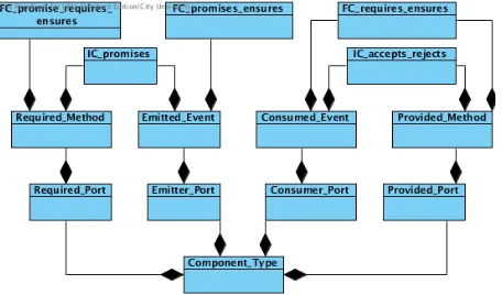
consumer for emitting events to outside and receiving events from outside respectively. Port type specification consists of contractually defined method or event actions, where con-tracts are two fold: interaction (@Interaction) and functional (@F unctional) contracts. Interaction contracts are specified with a set of interaction constraints (IC ∗ in Figure 1), while functional contracts with a set of functional constraints (F C ∗). The former is for specifying the state at which the action can be taken, the latter for specifying the acceptable set of parameters for the actions.
1Events in XCDdiffer from methods in that the former serves for one-way
while the latter for two-way (request-response) communication.
[image:3.612.323.551.132.266.2]Interaction constraints have precedence over the functional in that the the former has to be met which then leads to the latter being checked for a successful action execution. Moreover, as shown in Figure 1, each port type has its own specific constraints that are imposed on its action. The rest of this section illustrates these different constraint types.
Fig. 1: Meta-model of component ports
1) Required Port: Listing 2 exemplifies a required port specification through which a client components can make a
request call to a server. Constrained with IC promises in lines 2-4, the call for request is delayed until the promised
(pre) condition is met, the component data opened eval-uating to true. When a connection is opened, then the
F C promises requires ensuresin lines 5-12 can be evalu-ated. There in line 6, the parameter of therequestarepromised
to be equal to self (i.e., the id of the component). In this case, upon receiving the response from the provided port of a server, if the requirementthat an exception is not thrown is satisfied, the data serverReply is ensuredto be equal to the received result; otherwise (lines 10-11), the component state is not changed.
Listing 2: Required port specification
1required port client_port1{ 2 @Interaction{
3 @promises: \when(opened);
4 }
5 @Functional{
6 @promises: caller == self; 7 @requires: !\exception;
8 @ensures: serverReply=\result ; 9 @otherwise
10 @requires: \exception; 11 @ensures: true; 12 }
13 int request(ID caller);
14}
2) Provided Port: Listing 3 exemplifies a provided port specification. The port server port1 receives calls for the method request from clients. Upon receiving a call for the
request, first the IC accepts rejects in lines 2-6 are eval-uated. The call is accepted when the initialised data is
true. However, the call isrejected(line 5) if theinitialised
evaluates to f alse, indicating chaotic behaviour. When the
accepts condition is met,then the F C requires ensures in lines 7-13 are evaluated. If the requirement that the caller
result to be returned is assigned to 3. If however the caller is unassigned (lines 11-12), then a N ullID Exception is
ensured to be thrown to the client.
Listing 3: Provided port specification
1provided port server_port1{ 2 @Interaction{
3 @accepts: \when(initialised); 4 @otherwise
5 @rejects: \when(!initialised);
6 }
7 @Functional{
8 @requires: !(caller == null);
9 @ensures: numOfrequests++ && \result = 3;
10 @also
11 @requires: caller == null;
12 @ensures: \throws(NullID_Exception); 13 }
14 int request(ID caller);
15}
3) Emitter Port: Listing 4 exemplifies an emitter port speci-fication. There, the portclient port2emits an eventinitialise
to a server. Note that unlike methods, event are specified without return types – only names and parameters allowed in its signature. Constrained with anIC promises, the emission of the event initialise is delayed until what is promised
is met, i.e., the component data opened is true. When the client opens its connection, then theF C promises ensures
in lines 5-8 is evaluated. It states that the actual parameter of the initialise to be emitted is promised to be the id of the client which then ensures that the dataisInitialised istrue. Note also that due to supporting one-way communication, unlike two-way required ports emitter event ports do not wait for a response from the connected consumer ports. Nor do the consumer ports, unlike provided ports, send response after they receive an event.
Listing 4: Emitter port specification
1emitter port client_port2{ 2 @Interaction{
3 @promises: \when(opened);
4 }
5 @Functional{
6 @promises: client == self; 7 @ensures: isInitialised = true;
8 }
9 initialise(ID client);
10}
4) Consumer Port: Listing 5 exemplifies a consumer port specification. The server port2 receives event initialise
from the emitter port of its clients specified in Listing 4. Constrained with IC accepts rejects, the event initialise
is accepted when the component data initialised is f alse. Otherwise, when initialised is true, the rejects condition holds leading to chaotic behaviour. When the server is not yet initialised, the eventinitialiseis received successfully leading to the IC accepts rejects in lines 7-11 being evaluated. There, the client parameter of the received initialise event is required to be non-null which then ensures that the client
argument is stored in the datainitialiser.
Listing 5: Consumer port specification
1consumer port server_port2{ 2 @Interaction{
3 @accepts: \when(!initialised); 4 @otherwise
5 @rejects: \when(initialised);
6 }
7 @Functional{
8 @requires: !(client == null); 9 @ensures: initialised = true &&
10 initialiser = client;
11 }
12 initialise(ID client);
13}
B. Connector Specification
XCDconnectors serve to represent decentralised protocols for the components interacting with each other. Given its structure in Listing 6, a connector type is specified withroles
[image:4.612.321.558.322.484.2]andchannels. Each role represents a component interacting via the connector and it defines the protocol which the component obeys for avoiding chaotic behaviour. A role is described with data, and port-variables. The port-variables of a role essentially represent the respective ports of the components playing the role. Channels of an XCDconnector represent the communication links between interacting role port-variables and can have different types, e.g., synchronous, buffered, etc.
Fig. 2: Meta-model of connector role port-variables
As shown in Figure 2, port-variable actions are speci-fied solely with interaction constraints (IC waits ensures).
IC waits ensures is specified as interaction contracts that serves to delay the respective port actions occurring until a certain condition holds. Through the interaction contracts, port-variables of roles essentially impose high-level interac-tion protocols on the component(s) acting as the roles. The interaction protocols are intended for enforcing components to behave in a particular manner (i.e., through execution of certain action order). In doing so, components can be avoided from getting involved in unexpected (chaotic) interactions with other components associated with the same connector. The end result is then a set of components interacting with their environments successfully to compose the whole system.
components, along with their ports, are passed as parameters to the connectors whose roles they play.
Listing 6: Generic connector structure connector Name (rName{pvName,..},..) {
role rName {
data;*
provided port_variable pvName { method;+ };*
required port_variable Name { method;+ };*
emitter port_variable Name {
event;+ };*
consumer port_variable Name {
event;+ };*
}
channel;+ }
Listing 7 exemplifies a connector type specification for mediating the interaction between a server and a client. Client role in lines 4-20 are played by client components; server role in lines 21-37 by server components. The port-variable client pv1 (lines 6-12) in the client role constrains the interaction behaviour of the client port1 in Listing 2; the @interactioncontract herein delays the calls for method
request until the role data isInitialised is true. The
client pv2 is matched with client port2 and it updates the
isInitialised role data when the client port2 emits event
initialise.
The @interaction specified in the server pv1 of the server role (lines 23-29) constrains the server port1 in List-ing 3 so that call for method request cannot be accepted until the role datainitialisedbecomestrue. Therefore, client and server components are prevented from interacting before they ensure that server is initialised thus avoiding chaos. Just likeclient pv2, theserver pv2matching withserver port2
updates theinitialisedrole data when the eventinitialiseis received by the port.
The channel specification in lines 38-41 essentially de-scribes the component port pair that are to communicate with each other. Indeed, the client port playing the client pv1
communicates with the server port playing the server pv1, while the one playing the clients pv2 with the one playing the server pv2.
C. Configuration Specification
Component types explained in section 2.A can also be composite thus embodying configuration of component and connector instances. In doing so, they can represent either the abstractions for complex functional units where the internal behaviour is specified via configuration and external via the ports, or system architectures without any port specifications.
Listing 8 is the composite component type representing the system architecture of a client-server system. The component instance cIns is instantiated from the client component type whose ports are specified in Listing 2 and Listing 4; sIns
is from the server component whose ports are specified in Listing 3 and Listing 5. The connector type in Listing 7 is instantiated ascsIns. ThecsInsreceives as actual parameters the component instances and their ports thus associating the components and the roles they play.
Listing 7: A connector specification
1connector client2server(
2 client{client_pv1,client_pv2},
3 server{server_pv1,server_pv2}) {
4 role client{
5 bool isInitialised = false;
6 required port_variable client_pv1{ 7 @Interaction{
8 waits: \when(isInitialised); 9 ensures: true;
10 }
11 int request(ID caller);
12 }
13 emitter port_variable client_pv2{ 14 @Interaction{
15 waits: \when(!isInitialised); 16 ensures: isInitialised = true;
17 }
18 int initialise(ID caller);
19 }
20 }
21 role server{
22 bool initialised = false;
23 provided port_variable server_pv1{ 24 @Interaction{
25 waits: \when(initialised); 26 ensures: true;
27 }
28 int request(ID caller);
29 }
30 consumer port_variable server_pv2{ 31 @Interaction{
32 waits: \when(!initialised); 33 ensures: initialised = true;
34 }
35 int initialise(ID caller);
36 }
37 }
38 channel clients2server_req(client.client_pv1,
39 server.server_pv1);
40 channel clients2server_init(client.client_pv2,
41 server.server_pv2);
42}
Listing 8: A configuration specification
1 component client_server(){ 2 component client cIns(); 3 component server sIns(); 4 connector client2server csIns
5 (cIns{client_port1, client_port2},
6 sIns{sever_port1, server_port2} );
7 }
III. FORMALSEMANTICS OFXCD
In section 2, we informally explain the semantics of XCD
A. Component Semantics
For simplicity, we only consider herein the mappings of primitive components that do not include component/connector instances. The semantics below is given in terms of parallel interaction of FSP processes.
Definition 1 The semantics of a component with data D
and ports p1, .., pn is the composite FSP process:
PDc ||Pp1 .. ||Ppn (1)
where PDc is the data process and Pp1,..., Ppn each is a
composite port process whose definition is:
PIC || PF Ca1..|| PF Cam (2)
where PIC is the interaction constraints process and
PF Ca1..,PF Cam each is a process for a functional constraints
imposed on a single method/event action taken via the port.
1) Component Data: Acting as component memory, the data processPDstores the component data as index variables of its sub-processD. The processD executesreadandwrite
actions in a random order where the read has index variables holding the current data values (V), and the write has variables (V n) holding the new data values to overwrite the current values of the D 2.
1PD = D([InitialValue(V)])*,
2D([Name(V):Type(V)])* =(
3 read([Name(V)])* → D([Name(V)])*
4 | write([Name(V)_n:Type(V)])* → D([Name(V)_n])*
5).
Following the pattern above, a client component type with the dataopened,isInitialised, andserverReplywhose types are boolean, boolean, and integer respectively and whose initial values are f alse, f alse, and 0 respectively is transformed to the below FSP process.
1 P D = D[f a l s e] [f a l s e] [ 0 ] ,
2 D[ o p e n e d : B o o l ] [ i s I n i t i a l i s e d : B o o l ] 3 [ s e r v e r R e p l y : I n t ] = (
4 r e a d [ o p e n e d ] [ i s I n i t i a l i s e d ] [ s e r v e r R e p l y ]→ 5 D[ o p e n e d ] [ i s I n i t i a l i s e d ] [ s e r v e r R e p l y ] 6 | w r i t e [ o p e n e d n : B o o l ] [ i s I n i t i a l i s e d n : B o o l ] 7 [ s e r v e r R e p l y n : I n t ]→
8 D[ o p e n e d n ] [ i s I n i t i a l i s e d n ] [ s e r v e r R e p l y n ] 9 ) .
2) Component Interaction Constraints: As aforementioned, the interaction constraints for a port are mapped toPIC.PIC includes a sub-process P ort which firstly locks component data and performsreadaction to obtain the component state. Upon reading the data, then, for each event/method action of the port, a code snippet is produced in the body part.
1PIC( ID = 1 ) = P o r t ,
2P o r t = ( l o c k→ r e a d ( [ Name (V) : Type (V) ] ) * 3 → P ( [ Name (V) ] ) * ) ,
4P ( [ Name (V) : Type (V) ] ) * = (
5 ∀action∈port.actionList
6 . . body p a r t . . 7) .
If the port is of emitter/required type, the body part is produced with the following pattern. There, for each functional constraint (f c) on the current action a when wait statement is produced, with the guard
2Note that star (∗) implies zero or more, while question mark (?) zero or
one in the FSP mapping patterns.
W
ic∈action.@interactionpromises(ic). This states that an ac-tion is performed when at least one of the interacac-tion con-straints (promises) is met. Upon its satisfaction, the even-t/method action is emitted/sent, as in line 3, which stores the promised values of the parameters (obtained via f c) as its index variables. In case the port is required type, the process is blocked until it gets synchronised with the provided port process on the response action, as in line 4, which includes in its index variables the result/exception. Then, the control is passed to the process PF C through the internal action in line 5. Note that it is the PF C that executes the functional constraints thus updating component data.PF C then responds with another internal action as in line 7 where new data values are stored in the index variables (V n). The component memory is updated with the new data values by executing
writeaction, and then the memory is released withunlock.
1∀f c∈action.@f unctional
2 when (Wic∈action.@interactionp r o m i s e s( i c ) ) 3 p o r t a c t i o n e / r ( [promises(f c, arg)] ) *→
4 ( p o r t a c t i o n r ( [promises(f c, arg)] ) * [ r : RES ] [ e : EX ] ) ? 5 → i n t e r n a l a c t i o n ( [ Name ( a r g ) ] ) * ( [ Name (V) ] ) *
6 ( [ r ] [ e ] ) ?
7 → i n t e r n a l a c t i o n ( [ Name ( a r g ) ] ) * ( [ Name (V) ] ) * 8 ( [ Name (V n ) : Type (V) ] ) * 9 → w r i t e ( [ Name (V n ) ] ) *
10 → u n l o c k→ P o r t
Below is the FSP process for instance that is obtained by transforming the required port of the client component,
client port1 specified in Listing 2:
1PIC( ID = 1 ) = P o r t , 2P o r t = ( l o c k→
3 w r i t e [ o p e n e d : B o o l ] [ i s I n i t i a l i s e d : B o o l ] 4 [ s e r v e r R e p l y : I n t ]→
5 P [ o p e n e d ] [ i s I n i t i a l i s e d ] [ s e r v e r R e p l y ] ) , 6P [ o p e n e d : B o o l ] [ i s I n i t i a l i s e d : B o o l ]
7 [ s e r v e r R e p l y : I n t ] = ( 8 when ( o p e n e d )
9 r e q u e s t [ ID ]→ r e q u e s t [ ID ] [ r : RES ] [ e : EX ]
10 → i n t e r n a l r e q u e s t [ ID ] [ o p e n e d ] [ i s I n i t i a l i s e d ] 11 [ s e r v e r R e p l y ] [ r ] [ e ]
12 → i n t e r n a l r e q u e s t [ ID ] [ o p e n e d ] [ i s I n i t i a l i s e d ] 13 [ s e r v e r R e p l y ] [ o p e n e d n : B o o l ]
14 [ i s I n i t i a l i s e d n : B o o l ] [ s e r v e r R e p l y n : I n t ] 15 → w r i t e [ o p e n e d n ] [ i s I n i t i a l i s e d n ]
16 [ s e r v e r R e p l y n ] 17 → u n l o c k→ P o r t 18) .
If the port is of consumer/provided type, the body part, following the below pattern, includes a single when wait statement, with its guard W
ic∈action.@interactionaccepts(ic). This states an action is accepted when at least one of the interaction constraints (accepts) are met. Thus, this leads to the event/method action being executed as in line 2. Next, just like emitter/required ports, the control is passed to the processPF C through the internal action in line 3. PF C then responds with another internal action as in lines 4-6 where new data values are stored in the index variables (V n) and in the case of provided ports so are the result/exception ([r:RES][e:EX]). The component memory is updated with the new data values by executing write action, and then the memory is released withunlock. In the case of provided ports, a response action is executed as in line 9 which includes as index variables the action arguments and result/exception.
when statement is for rejects, as in lines 11-12, whose satisfaction leads toERRORstate due to chaotic behaviour.
1when (Wic∈action.@interactiona c c e p t s( i c ) ) 2 p o r t a c t i o n c / p ( [N ame(arg) :T ype(arg)] ) * 3 → i n t e r n a l a c t i o n ( [ Name ( a r g ) ] ) * ( [ Name (V) ] ) * 4 → i n t e r n a l a c t i o n ( [ Name ( a r g ) ] ) * ( [ Name (V) ] ) * 5 ( [ Name (V n ) : Type (V) ] ) * 6 ( [ r : RES ] [ e : EX ] ) ? 7 → w r i t e ( [ Name (V n ) ] ) *
8 → u n l o c k
9 (→ p o r t a c t i o n p ( [arg] ) * [ r ] [ e ] ) ? 10 → P o r t
11 | when (Wrejects∈action.interactionr e j e c t s)
12 p o r t a c t i o n p ( [N ame(arg) :T ype(arg)] ) *→ERROR
From the server ports specified in Listing 3 and Listing 5, one can conclude that the server component has three data:
initialised, initialiser, and numOf requests whose types are bool,int, andintrespectively. Thus, the provided port of the server component, theserver port1specified in Listing 3, is for instance encoded as follows.
1PIC( ID = 1 ) = P o r t , 2P o r t = ( l o c k→
3 w r i t e [ i n i t i a l i s e d : B o o l ] [ i n i t i a l i s e r : I n t ] 4 [ n u m O f r e q u e s t s : I n t ]→
5 P [ i n i t i a l i s e d ] [ i n i t i a l i s e r ] [ n u m O f r e q u e s t s ] ) , 6P [ i n i t i a l i s e d : B o o l ] [ i n i t i a l i s e r : I n t ]
7 [ n u m O f r e q u e s t s : I n t ] = ( 8 when ( i n i t i a l i s e d ) 9 r e q u e s t [ c a l l e r : I n t ]
10 → i n t e r n a l r e q u e s t [ c a l l e r ] [ i n i t i a l i s e d ] 11 [ i n i t i a l i s e r ] [ n u m O f r e q u e s t s ] 12 → i n t e r n a l r e q u e s t [ c a l l e r ] [ i n i t i a l i s e d ] 13 [ i n i t i a l i s e r ] [ n u m O f r e q u e s t s ]
14 [ i n i t i a l i s e d n : B o o l ] [ i n i t i a l i s e r n : I n t ] 15 [ n u m O f r e q u e s t s n : I n t ] [ r : RES ] [ e : EX] 16 → w r i t e [ i n i t i a l i s e d n ] [ i n i t i a l i s e r n ] 17 [ n u m O f r e q u e s t s n ]
18 → u n l o c k→ r e q u e s t [ c a l l e r ] [ r ] [ e ]→ P o r t 19 | when ( ! i n i t i a l i s e d )
20 r e q u e s t [ c a l l e r : I n t ]→ERROR 21) .
3) Component Functional Constraints: As aforementioned, the process PF C is produced for each event/method action of a port to compute the respective functional behaviour specified via @f unctional contract. The control is passed from PIC to the PF C through the internal action in lines 3-4. Note that in the case of required ports, the internal action includes also[r:RES][e:EX]which are the index variables communicating the result/exception received from the response action (port action r) in PIC. Then, for each functional constraint (f c) on the action, a whenstatement is produced whose guard is the requires condition of the f c. When the guard istrue, the internal action is responded to thePICagain along with new data values (ensures(V)), derived from the
ensures of the f c, as index variables. Note that if the port is provided the result/exception calculated are also passed as index variables ([r0][e0] in line 8).
1∀action∈port.actionList
2 PF C(ID= 1) = (
3 i n t e r n a l a c t i o n ( [ Name ( a r g ) : Type ( a r g ) ] ) * 4 ( [ Name (V) : Type (V) ] ) * ( [ r : RES ] [ e : EX ] ) ?
5 →(∀f c∈@f unctional
6 when (requires(f c))
7 i n t e r n a l a c t i o n ( [ Name ( a r g ) ] ) * ( [ Name (V) ] ) * 8 (e n s u r e s(V) ] ) * ( [ r ’ ] [ e ’ ] ) ?
9 →PF C
10 )
11 ) .
Following is, for instance, the FSP process for func-tional constraints on the method requestprovided by the the
server port1 specified in Listing 3.
1PF C(ID= 1) = (
2 i n t e r n a l r e q u e s t [ c a l l e r : ID ] [ i n i t i a l i s e d : B o o l ] 3 [ i n i t i a l i s e r : I n t ] [ n u m O f r e q u e s t s : I n t ] 4 →( when ( c a l l e r ! = NULL)
5 i n t e r n a l r e q u e s t [ c a l l e r ] [ i n i t i a l i s e d ] 6 [ i n i t i a l i s e r ] [ n u m O f r e q u e s t s ] 7 [ i n i t i a l i s e d ] [ i n i t i a l i s e r ]
8 [ n u m O f r e q u e s t s + 1 ] [ 3 ] [ N O E x c e p t i o n ]→PF C 9 | when ( c a l l e r == NULL)
10 i n t e r n a l r e q u e s t [ c a l l e r ] [ i n i t i a l i s e d ] 11 [ i n i t i a l i s e r ] [ n u m O f r e q u e s t s ] 12 [ i n i t i a l i s e d ] [ i n i t i a l i s e r ] [ n u m O f r e q u e s t s ] 13 [NULL ] [ NULLIDException ]→PF C) 14) .
B. Connector Semantics
Like components, the semantics of connectors are also defined in terms of parallel interaction of FSP processes.
Definition 2 The semantics of a connector with rolesr1,...,
rn channelsch1,...,chn is the composite process:
Pr1 .. ||Prn (3)
wherePr1..., Prn each is a role process whose definition is:
PDr || Ppv1 .. ||Ppvn (4)
where PDr is the data process and Ppv1,..., Ppvn each is a
port-variable process that represents the interaction constraints imposed on method/event actions taken by the port-variable.
While role data is mapped to a process in the same way as the component data, port-variables in a role are mapped in a different way from component ports. This is due to port-variable imposing solely interaction constraints on actions.
Below is the pattern followed in mapping a port-variable of any of the four types into an FSP process (Ppv). Firstly, role memory islockedand data arereadas in line 2. Next, in lines 5-10, the interaction constraints of the port-variable are evaluated. For each action of the port-variable, a set of when
wait statement is produced each corresponding to a unique
waitsclause specified in the action’s@interactioncontract. The guard of each when is the condition specified via the respectivewaitsclause. Upon satisfaction of any of thewhen
guards, i.e., the @interaction of the action is met, then the event/method action is executed as in line 8. This is followed by the writeaction which updates the role memory with the new data values (V n) imposed by theensuresof the ic.
1Ppv( ID = 1 ) = P o r t v a r ,
2P o r t v a r = ( l o c k→ r e a d ( [ Name (V) : Type (V) ] ) * 3 → Pv ( [ Name (V) ] ) * ) ,
4Pv ( [ Name (V) : Type (V) ] ) * =
5(∀action∈portvar.actionList
6 ∀waits∈action.@interaction
7 when (waits)
8 pv a c t i o n e /m( [N ame(arg) :T ype(arg)] ) * 9 →w r i t e ( [ Name (V n ) ] ) * → u n l o c k 10 → P o r t v a r
11) .
1Ppv( ID = 1 ) = P o r t v a r ,
2P o r t v a r = ( l o c k→ r e a d [ i n i t i a l i s e d : B o o l ] 3 → Pv [ i n i t i a l i s e d ] ) ,
4Pv [ i n i t i a l i s e d : B o o l ] = ( 5 when ( i n i t i a l i s e d )
6 r e q u e s t [ c a l l e r : I n t ] →w r i t e [ i n i t i a l i s e d ] 7 →u n l o c k→ P o r t v a r ) .
Channels of a connector are mapped to relabelling func-tions (/) employed in the composite process corresponding to the connector. The relabelling function, for each channel, re-names the actions taken by the provided/consumer port-variable in one end of the channel to the names of the respective actions taken by the required/emitter port-variable in the other end. This enables the port-variable processes to synchronise on these actions.
C. Configuration Semantics
Just like component and connector types, configuration of system architectures is encoded into a set of FSP processes.
Definition 3 The semantics of a configuration with its com-ponent instancesc1,..,cn and connector instancescn1,..,cnn is
the composite process:
||c∈c1..cn(c:PDc || r1:PDr1..|| rn:PDrn || Pc2rs) (5)
where, for each component c, its data process is PDc, the
data process for each role the component plays is PDr; and
Pc2rsfor the componentcplaying a set of rolesrsis another composite process:
Pp12pvs..||Ppn2pvs (6)
wherePp2pveach represents a port of the component matching with a set of port-variablespvsand is also a composite process:
c1:Pp1||r1:Ppv1, ..,||rn :Ppvn (7)
where Pp1 represent a single port of the component and Ppv
each a single port-variable matching with the port and all are primitive processes.
Note that component data, role data, port, and port-variable processes are all produced in the way explained in section 3. For each instance of the component, role, port and port-variable, these respective processes are instantiated through prefixing feature of FSP (i.e., process actions are prefixed with labels). As shown above, we use labels as ids of the elements, e.g., component id cid. It is then the prefix labels that determines during the verification which action belongs to whom.
Synchronous communication among processesPort (Pp) and port-variable (Ppv) processes in formula 7 communicate with each other through synchronisation on actions. As shown below, if a port-variable is of required/emitter type, its process actions are re-named to the respective actions of the matching port enabling them to get synchronised with each other.
1 p o r t a c t i o n e / r / p v a c t i o n e / r
In the case of provided/consumer types, as shown below, the re-naming process is a bit more complicated. (1) in the below pattern is performed by the provided/consumer port-variable processes as mentioned in section 4. Re-naming the provid-ed/consumer port-variable actions to those of the connected required/emitter port-variables, synchronous communication between the connected port-variables are enabled. Then in
step 2, the re-named actions of the consumer/provided port-variables are again renamed to the actions of the associated port, i.e., the required/emitter port due to having been renamed to required/emitter port-variable actions in (1). When the step 3 is completed and the provided/consumer port actions are also re-named to the same actions of the required/emitter ports as in (2), then the ports that are connected via their port-variables can communicate synchronously in a way that is restricted by their port-variable processes.
1p v a c t i o n e / r / p v a c t i o n c / p 2p o r t a c t i o n e / r / p v a c t i o n e / r 3p o r t a c t i o n e / r / p o r t a c t i o n c / p
IV. RELATEDWORK ANDDISCUSSION
DbC is quite new to the area of software architecture speci-fication. It has so far been mainly considered for programming languages facilitating the checking of software correctness. JML is one of the well-known examples [6], [8], [9] allowing to specify executable contracts for Java classes and interfaces.
Beugnard et al.’s approach [3] is considered highly inspir-ing that applies DbC to component based software engineerinspir-ing. They proposed four types of component contracts: basic, behavioural, synchronisation, and quality-of-service contracts. However, components, just like Java classes, are considered here only with provided interfaces ignoring explicit specifica-tion of required interfaces and also interfaces of events. Fur-thermore, focussing on components only, Beugnard et al. does not consider contractual specification of complex connectors, i.e., interaction protocols.
There are a very few attempts towards applying DbC to software architecture specification, e.g., RADL [26] and CBabel [5]. RADL, above all, supports only methods that can be provided or required, neglecting explicit specification of events. Furthermore, their consideration of contracts serve basically to check compatibility of components, i.e., whether their required and provided ports (inter)operate as expected; the behaviour of components are specified using finite state ma-chine. CBabel ADL, by contrast, supports explicit specification of events too. However, they apply contracts to coordination aspect of software architectures; component behaviour cannot be contractually specified.
As aforementioned, most of the formal ADLs (e.g., Darwin [15], Wright [2], LEDA [7], SOFA [25], CONNECT [12], and etc.) adopt process algebra notations which are found unusual among industry. Indeed, specifying behaviour of components and connectors in terms of concurrently executing processes and their parallel interaction is commonly considered as com-plicated thus error-prone. Whereas, with formal DbC contracts, component behaviours are specified simply by defining when a component is to take an action (pre-condition) and what is expected to happen then (post-condition). Indeed, the XCD
specification of client-server system in section 2 describes exactly the same behaviour as its mapping to FSP presented in section 3 and 4, surely in a more user-friendly way.
to specify functional behaviour of components and the latter either to specify their interaction behaviour or the interaction protocol of connectors. Furthermore, with the introduction of new contract clauses, e.g., promises, waits, accepts, and rejects, designers are allowed to express behaviour of method/event actions in a more precise and complete way.
V. CONCLUSION
In this paper, we presented a series of extensions to DbC for adapting it to software architecture design. Unlike current DbC implementations, we considered a more systematic and comprehensive approach. Using our XCDlanguage, designers can specify the behaviour of their components in terms of explicit interaction and functional contracts where the former describes the interaction behaviour and the latter the functional behaviour. Furthermore, components can have four types of ports (interfaces) – required, provided, emitter, and consumer – allowing designers to apply contracts not only on the actions provided to outside, but also required actions from them and on events emitted/consumed too.
Treating interaction protocols explicitly as connectors in ar-chitectural designs, XCDalso enables the contractual specifica-tion of connectors. They are specified with interacspecifica-tion contracts for participating components. Thus, components interacting through the connectors are ensured to adhere to interaction protocols in their behaviours.
Furthermore, we present the formal semantics of XCD
by means of the mapping algorithms of XCD elements to processes in Finite State Process (FSP). Therefore, it is made evident how easy it is to perform formal verification of XCD
specifications against safety and liveness properties.
VI. ACKNOWLEDGEMENTS
This work has been partially supported by the EU project FP7-257367 IoT@Work – “Internet of Things at Work”.
REFERENCES
[1] Alessandro Aldini, Marco Bernardo, and Flavio Corradini. A Process Algebraic Approach to Software Architecture Design. Springer, 2010.
[2] Robert Allen and David Garlan. A formal basis for architectural connection. ACM Trans. Softw. Eng. Methodol., 6(3):213–249, 1997. [3] Antoine Beugnard, Jean-Marc J´ez´equel, and No¨el Plouzeau. Making
components contract aware. IEEE Computer, 32(7):38–45, 1999. [4] Dines Bjørner and Cliff B. Jones, editors. The Vienna Development
Method: The Meta-Language, volume 61 ofLecture Notes in Computer Science. Springer, 1978.
[5] Christiano Braga and Alexandre Sztajnberg. Towards a rewriting semantics for a software architecture description language.Electr. Notes Theor. Comput. Sci., 95:149–168, 2004.
[6] Lilian Burdy, Yoonsik Cheon, David R. Cok, Michael D. Ernst, Joseph R. Kiniry, Gary T. Leavens, K. Rustan M. Leino, and Erik Poll. An overview of JML tools and applications.STTT, 7(3):212–232, 2005. [7] Carlos Canal, Ernesto Pimentel, and Jos´e M. Troya. Specification and refinement of dynamic software architectures. In Patrick Donohoe, editor, WICSA, volume 140 of IFIP Conference Proceedings, pages 107–126. Kluwer, 1999.
[8] Patrice Chalin, Joseph R. Kiniry, Gary T. Leavens, and Erik Poll. Beyond assertions: Advanced specification and verification with JML and ESC/Java2. In Frank S. de Boer, Marcello M. Bonsangue, Susanne Graf, and Willem P. de Roever, editors,FMCO, volume 4111 ofLecture Notes in Computer Science, pages 342–363. Springer, 2005.
[9] Yoonsik Cheon and Gary T. Leavens. A simple and practical approach to unit testing: The JML and JUnit way. In Boris Magnusson, editor,
ECOOP, volume 2374 ofLecture Notes in Computer Science, pages 231–255. Springer, 2002.
[10] C. A. R. Hoare. An axiomatic basis for computer programming.
Commun. ACM, 12(10):576–580, 1969.
[11] C. A. R. Hoare. Communicating sequential processes.Commun. ACM, 21(8):666–677, 1978.
[12] Val´erie Issarny, Amel Bennaceur, and Y´erom-David Bromberg. Middleware-layer connector synthesis: Beyond state of the art in middleware interoperability. In Marco Bernardo and Val´erie Issarny, editors,SFM, volume 6659 ofLecture Notes in Computer Science, pages 217–255. Springer, 2011.
[13] David Janzen and Hossein Saiedian. Test-driven development: Con-cepts, taxonomy, and future direction. IEEE Computer, 38(9):43–50, 2005.
[14] Christos Kloukinas and Mert Ozkaya. Xcd - Modular, realizable software architectures. In Corina S. Pasareanu and Gwen Sala¨un, editors, FACS, volume 7684 of Lecture Notes in Computer Science, pages 152–169. Springer, 2012.
[15] Jeff Magee and Jeff Kramer. Dynamic structure in software architec-tures. InSIGSOFT FSE, pages 3–14, 1996.
[16] Jeff Magee and Jeff Kramer. Concurrency - state models and Java programs (2. ed.). Wiley, 2006.
[17] Jeff Magee, Jeff Kramer, and Dimitra Giannakopoulou. Analysing the behaviour of distributed software architectures: a case study. InFTDCS, pages 240–247. IEEE Computer Society, 1997.
[18] Ivano Malavolta, Patricia Lago, Henry Muccini, Patrizio Pelliccione, and Antony Tang. What industry needs from architectural languages: A survey.IEEE Transactions on Software Engineering, 99, 2012. [19] E.M. Maximilien and L. Williams. Assessing test-driven development
at IBM. In25thIntl. Conf. on Software Engineering, pages 564–569, May 2003.
[20] Bertrand Meyer. Applying “Design by Contract”. IEEE Computer, 25(10):40–51, 1992.
[21] Bertrand Meyer, Jean-Marc Nerson, and Masanobu Matsuo. Eiffel: Object-oriented design for software engineering. In Howard K. Nichols and Dan Simpson, editors, ESEC, volume 289 of Lecture Notes in Computer Science, pages 221–229. Springer, 1987.
[22] Robin Milner, Joachim Parrow, and David Walker. A calculus of mobile processes, i. Inf. Comput., 100(1):1–40, 1992.
[23] OMG. Common object request broker architecture (CORBA) specifi-cation, version 3.3 – Part 3: CORBA component model. Specification formal/2012-11-16, OMG, November 2012. //omg.org/spec/CORBA/3. 3/.
[24] OSGi Alliance. OSGi core release 5. Specification, March 2012. // osgi.org/.
[25] Frantisek Plasil and Stanislav Visnovsky. Behavior protocols for software components. IEEE Trans. Software Eng., 28(11):1056–1076, 2002.
[26] Ralf Reussner, Iman Poernomo, and Heinz W. Schmidt. Reasoning about software architectures with contractually specified components. In Alejandra Cechich, Mario Piattini, and Antonio Vallecillo, editors,
Component-Based Software Quality, volume 2693 ofLecture Notes in Computer Science, pages 287–325. Springer, 2003.
[27] Mary Shaw, Robert DeLine, Daniel V. Klein, Theodore L. Ross, David M. Young, and Gregory Zelesnik. Abstractions for software architecture and tools to support them. IEEE Trans. Software Eng., 21(4):314–335, 1995.
[28] Andre Luiz Camargos Tavares and Marco Tulio de Oliveira Valente. A gentle introduction to OSGi. ACM SIGSOFT Software Engineering Notes, 33(5), 2008.
[29] Rob C. van Ommering, Frank van der Linden, Jeff Kramer, and Jeff Magee. The koala component model for consumer electronics software.