City, University of London Institutional Repository
Citation
:
Zhou, B., Yang, S., Sun, T. & Grattan, K. T. V. (2015). A Novel Wireless Mobile
Platform to Locate and Gather Data From Optical Fiber Sensors Integrated Into a WSN.
IEEE Sensors Journal, 15(6), pp. 3615-3621. doi: 10.1109/JSEN.2015.2396040
This is the accepted version of the paper.
This version of the publication may differ from the final published
version.
Permanent repository link:
http://openaccess.city.ac.uk/12792/
Link to published version
:
http://dx.doi.org/10.1109/JSEN.2015.2396040
Copyright and reuse:
City Research Online aims to make research
outputs of City, University of London available to a wider audience.
Copyright and Moral Rights remain with the author(s) and/or copyright
holders. URLs from City Research Online may be freely distributed and
linked to.
City Research Online:
http://openaccess.city.ac.uk/
[email protected]
A Novel Wireless Mobile Platform to Locate and
Gather Data From Optical Fiber Sensors
Integrated Into a WSN
Bochao Zhou, Shuo Yang, Tong Sun, and Kenneth T. V. Grattan
Abstract— This paper presents a novel design for a wireless
mobile platform to locate and gather data from different types of optical fiber sensors, thereby enabling the more effective integration of a number of such optical fiber sensors with an advanced mobile wireless sensor network (WSN). This then more readily permits potential applications, such as monitoring in remote and harsh environments and tracking, exploiting fully the combined advantages offered both by the mobile WSN and the advanced optical fiber sensing technologies. The platform which was designed and implemented consists of an optical fiber sensor module and a smart mobile WSN module, which shows important advantages for mobile sensing and tracking and mesh networking. In this paper, a fiber Bragg grating-based temperature sensor and an intrinsic pH optical fiber sensor were specially designed and integrated successfully into the optical fiber sensor module as an exemplar to investi-gate the performance of the integrated system based on the mobile WSN platform. The positive experimental results obtained have confirmed the functionality of the platform designed and demonstrated its capacity for real-time optical fiber sensor data monitoring, processing, and wireless transmission. The successful creation of this type of wireless mobile platform with optical fiber sensors can thus be expected to make an important impact on a number of sectors, where either conventional optical sensor designs or WSNs alone cannot meet the systems requirements.
Index Terms— Wireless sensor network, optical fiber sensors,
pH sensor, mobile control, RSSI localization.
I. INTRODUCTION
O
PTICAL fiber sensors have wide-ranging potentialin sensing and measurement and have been able to demonstrate a number of advantages over conventional sensor
This work was supported in part by the Engi-neering and Physical Sciences Research Council under Grant EP/J013552/1, in part by the European Commission through the Pollins Project underGrant 606079, in part by the Green Dragons Research Fund through City University London, London, U.K., in part by the Royal Academy of Engi-neering, and in part by theGeorge Daniels Educational Trust.The associateeditor coordinating thereview of thispaper and approvingit forpublicationwas Dr.ThiloSauter.
B. Zhou, S. Yang, and T. Sun are with the Photonics and Instrumen-tation Research Centre, School of Mathematics, Computer Science and Engineering, City University London, London EC1V 0HB, U.K. (e-mail: [email protected]; [email protected]; [email protected]).
K. T. V. Grattan is with the Photonics and Instrumentation Research Centre, School of Mathematics, Computer Science and Engineering, City University London, London EC1V 0HB, U.K., and also with the City Graduate School, City University London, London EC1V 0HB, U.K. (e-mail: [email protected]).
technology for a variety of applications [1]. However such optical fibre sensor systems are often used as ‘stand-alone’ devices in pre-defined positions: thus there is a need for extensive lengths of fibre optic cable connecting all the sensors as an optical fibre network and in many circumstances dealing with this cabling can be a problem. Wireless sensor networks (WSNs) have gained considerable, indeed world-wide attention in recent years and provide an effective means for acquiring information on parameters such as tempera-ture, pressure, acceleration, vibration and the measurement of chemical species, usually based on exploiting conven-tional Micro-Electro-Mechanical System (MEMS) sensors [2]. To date, although there have been some reports of the integration of optical sensors into a WSN platform e.g. by O’Connell et al [3], most WSN systems do not use optical fibre sensors and thus fail to benefit from the synergy of both technologies – accessing the advantages seen in the use of a wireless sensor networks and at the same time coupling these to the benefits of the advanced design and the significant capabilities of optical fibre sensors. In addition, mobile robots have been used widely to perform a wide range of critical tasks such as exploration, search and rescue operations, and reconnaissance [4]. In recent years, extensive research has been undertaken in the field of mobile network and robot control [5], [6]. All of these offer the potential to integrate mobile robots with a generic WSN platform, thus to form a mobile WSN platform to overcome the limitation arising from using a static WSN platform. Here this approach is coupled to an advanced optical sensor system, offering the flexibility to address various sensing needs arising from different envi-ronmental contexts – from dangerous or hazardous scenarios where there are radioactive, chemical, and other industrial-based issues to the more routine and mundane. However in all of these, high quality measurement is essential.
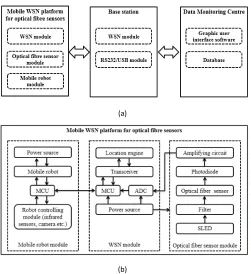
Fig. 1. (a) System architecture of the WSN platform for the optical fiber sensors. (b) Schematic of mobile WSN platform for the optical fibre sensors.
are used further to evaluate the functionality of the mobile WSN platform created while supporting Graphical User Interface (GUI) software, where robot control algorithms have been developed for sensor data monitoring and mobile robot controlling. The system is described and results of tests and evaluation carried out are reported.
II. PLATFORMDESIGN ANDIMPLEMENTATION
A. System Overview and Mobile WSN Platform
The system designed comprises three key components: the mobile WSN platform, the base station and the data monitoring centre, all of which is illustrated schematically in Figure 1(a). Each mobile WSN platform was integrated with a WSN module, coupled to computing and group communi-cation functionalities allowing for data transmission via multi-hop routing, an optical fibre sensor module with its in-build sensing capabilities and a mobile robot module which enables mobility of the platform and thus allowing the flexible in the sensing performance. The base station was used to collect the sensor data and then to transmit these data to a data monitoring centre for further recording, processing and display, which is based on Graphic User Interface (GUI) software and database system.
Figure 1(b) shows the detailed design of the mobile WSN platform. The platform contained three key compo-nents: the WSN module comprising a transceiver (CC2531, Texas Instruments Inc.) with a build-in location engine; an MCU (MSP430F5437, Texas Instruments Inc.); an analogue-to-digital converter (ADC); and a power source for data processing and network communication. The mobile robot
module used includes an inexpensive ‘off-the-shelf’ robot from Active Robots Ltd integrated with a robot controlling module (video camera module etc.) and an optical fibre sensor module.
B. Optical Fibre Sensor Designs
In this study, two sensors system were specially designed and implemented, these being representative devices from both physical and chemical optical fibre sensors, to test and evaluate the functionality of the mobile WSN platform created in a comprehensive way.
1) Sensor 1 – Physical Sensor – Fibre Bragg Grating (FBG)-Based Sensor System: The development of the Fiber
Bragg Grating (FBG) has been one of the milestone events in the history of optical communications and sensing [8] and provides an excellent basis for a sensor to be demonstrated in this way. The approach exploits the fact that a Fibre Bragg Grating (FBG) has an inherent sensitivity to strain and temperature, as it is well known that its resonance wavelength is dependent on the effective refractive index of the fibre core and the grating period [9]. Therefore such devices can be used for as the basis of sensor systems for the measurement of strain, temperature, or other measurands simply by monitoring the Bragg wavelength shift. The relationship governing the link between the wavelength shift and the measurand is given by:
λB =2ne f f (1)
whereλBis the Bragg wavelength, ne f f is the refractive index
of the fibre core, andis the Bragg grating period. The Bragg
wavelength depends on the effective index of refraction of the core and the periodicity of the grating and both of these will be affected by changes in temperature [9]. For the measurement of a constant strain, the shift in the Bragg wavelength can be expressed as:
λB =
1
∂
∂T
+ 1
ne f f
∂
ne f f
∂T
λBT (2)
The first term relates to the thermal expansion of the fibre
(typically 0.55×10⁻⁶for silica fibre), and the second relates
to the temperature dependence of the refractive index (approx-imately 8.6 pm/°C for Germania-doped, silica core fibre). It is clearly shown that the thermo-optic induced index change is the dominant effect. From Equation (2), the temperature sensitivity of a Bragg grating may vary between different materials. This forms the essence of the FBG-based sensor system used in this work which was configured here as a sensor only for temperature monitoring (with no external strain being applied to the fibre). Figure 2 shows the photograph to illustrate the complete FBG temperature sensor created for use with the WSN. The sensing probe, which contains a FBG at the tip, is protected by an aluminium tube which protects the sensor which was used in a series of experimental tests by subjecting the probe to various temperature conditions, as discussed.
2) Sensor 2 – Chemical Sensor – Intrinsic Optical Fibre pH Sensor System: The intrinsic optical fibre pH sensor used
Fig. 2. Photograph of the FBG temperature sensor created for a WSN protected by an aluminium tube.
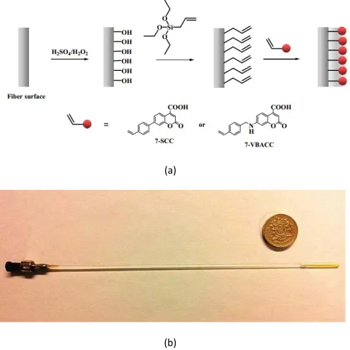
Fig. 3. (a) Schematic of the processes involved for preparation of the sensitive distal end of the pH sensor. (b) Photograph of the optical fiber pH sensor with the sensor material having been coated at the end surface of the fiber.
for use here. It was chosen as the sensor for use in this work not only as it is an effective exemplar of a sensor which can be effectively integrated into the mobile WSN platform but due to the importance of chemical sensors of this type for monitoring harsh working conditions, where conventional WSN sensors cannot work properly and thus integrating wireless technology with noise-immune fibre optics is particularly important.
As shown in Figure 3(a), the optical fibre pH sensor was created through a polymerization process, by covalent bonding of a novel fluorescent dye which was designed and synthesized specifically to provide an enhancement of the sensor sensitivity and stability, and integrated on the end surface of the optical fibre used. As reported previously [10], two different fluo-rescent dyes have been synthesized with their corresponding chemical structures also being shown in Figure 3(a). The sensor probe thus created and used in this work is shown in Figure 3(b). When the UV light from the light source was
transmitted to the sensor probe through a 1×2 fibre coupler,
the fluorescence signal generated by the pH sensor could be captured by a photodetector, which was connected to the other
Fig. 4. (a) Schematic diagram of the FBG-based temperature sensor module; SLED – superluminescent LED; PD – photodetector; Amp – electronic amplifier; ADC-analogue-to-digital converter. (b) Schematic diagram of the intrinsic optical fibre pH sensor system.
end of the 1×2 coupler. As a result, fluorescence detection was
used as the key optical transduction method, rather than the more conventional colorimetric method and this was employed in order to avoid interference from the light source and thus to achieve better system stability and sensitivity, making this also well suited for use with the WSN platform.
C. Optical Fibre Sensor Modules
[image:4.612.52.300.59.145.2] [image:4.612.50.297.199.446.2]with reference to the signal from FBG1, is captured by a photodiode prior to being converted into digital signals using an analogue-to-digital converter (ADC). The overall size of
the sensing module is 15cm×5.5 cm×4.5 cm, which has been
carefully designed to be able to interface easily with the WSN module and robotic system.
As shown in Figure 4(b), the intrinsic optical fibre pH sensor system itself operated by coupling light from a
UV light source to the sensor probe using a 1×2 fibre coupler,
where the other end of the fibre coupler was connected to a mini-spectrometer or a photo-detector and through a filter. When the sensor probe was subjected to different solutions with different pH values, the fluorescence signal generated from the sensor probe was then modulated by the pH of the solution and the result captured by the mini-spectrometer or a photodetector used in the system. The intrinsic optical fibre pH sensor module comprised a LED light source (operating at 375 nm, Roithner Laser Technik), the optical fibre pH sensor developed in the laboratory, a 488 nm long-pass edge filter (Laser 2000 Ltd UK), a photodiode (Laser 2000 Ltd UK) and an amplifying circuit and data acquisition system.
D. Software and Location Algorithm Used
The ZigBee standard is specifically targeted for wireless sensor network applications for reliable, low-power and remote monitoring and control and thus was chosen for this applica-tion. Based on TI’s industry-leading ZigBee protocol stack, Z-Stack, which is compliant with the ZigBee 2007 specifica-tion (ZigBee Pro.), was employed in this work for setting-up the wireless network supporting self-healing mesh networking. At the data monitoring centre, Graphical User Interface (GUI) software was designed and developed using Microsoft Visual Studio 2010 for device configuration, commissioning of net-works, linking devices and data processing from the base station. The sensor data and location information collected by each mobile node in the WSN system could be displayed using the GUI software interface in either textual or graphical format, with the capabilities to retrieve historical data and playback. In the case of the robot control, the localization iden-tification is of critical importance since the sensing data would be of limited value, should the location information were unknown for various applications [11]. In this work, a RSSI (Received Signal Strength Indicator) localization algorithm has been adopted and implemented in the robot controlling module and a video camera is also mounted on the robot to help with the navigation of the robot. The Location Engine which is integrated in the MCU of the targeted blind node enables the calculation of the distances between the blind node and the reference nodes through the broadcasting and receiving of related RF signals. All reference nodes have already been deployed and are assumed to know their own position. The known physical location of the static reference nodes combined with RSSI values obtained is able to provide the positional information for the targeted blind nodes.
[image:5.612.342.526.56.227.2]An outline of this localization system as used in this work is shown in Figure 5. The targeted blind node is programmed to query the entire network periodically for the static locations
Fig. 5. Schematic diagram of the RSSI localization algorithm.
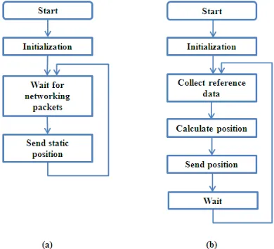
Fig. 6. Program flow of RSSI localization algorithm: (a) for reference node and (b) for blind node.
of all reference nodes that are within the transmission range and is configured to perform a position calculation. The pro-gramme flow chart is shown in Figure 6, but the procedure can be defined in three phases: broadcast, reference data collection and position calculation and reporting. The targeted blind node receives data packets from reference nodes and transforms the RSSI into distance values through measurement of the power strength of RF signal. By broadcasting and receiving data packets, the targeted blind node obtains the physical location information of the static reference nodes configured with X, Y and the distance values, which can be used to perform the posi-tion estimaposi-tion calculaposi-tion. The maximum-likelihood (ML) estimation is adopted in this study to calculate the estimated position of the targeted blind node by minimizing the differ-ences between the measured and estimated distances [12].
III. EXPERIMENTALSETUP AND
PERFORMANCEEVALUATION
[image:5.612.340.535.263.440.2]with the optical fibre sensors mounted on the robot through the WSN module and the robot location identification through the use of the localization algorithm and the analysis of the image information obtained from the video camera. The field test undertaken was designed to simulate a typical practical application scenario where the mobile robot is required to identify a point of interest in order for a measurement to be made, following which both the location information of the robot/sensor and the sensor data received at that specific position are required to be sent back to the base station for further signal analysis.
A. Experimental Setup for the Evaluation of the System
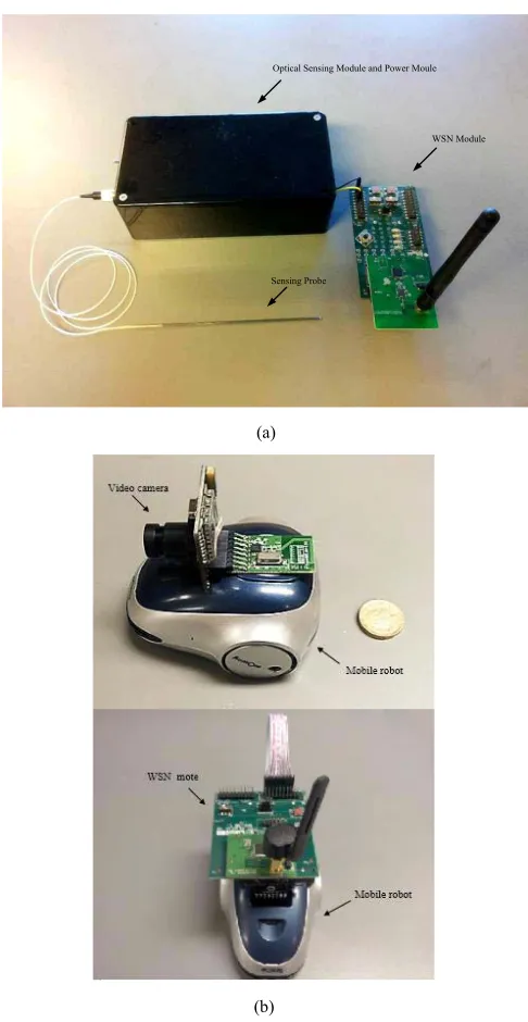
Figure 7(a) shows a complete optical fibre sensor system created for use with the mobile WSN, while the mobile robot module is illustrated in Figure 7(b).
B. Evaluation of the Integrated Platform – the WSN Module Integrated With the Optical
Fibre Sensor Module
Figure 8(a) shows the experimental data collected from the platform when the optical fibre sensor probe was placed in an environmental chamber for calibration, with the tempera-ture varying from 20 °C to 80 °C. The ordinate shows the signal level received (recorded in volts for this figure and for Figure 8(b)). The dynamic response of the sensor obtained from the WSN platform is displayed in the data monitoring centre. It was noticeable that the signal intensity decreased as expected with the increase of temperature, as it varied from 20 °C to 80 °C.
Figure. 8(b) shows the experimental data collected from the platform when the optical fibre sensor probe was inserted into various test solutions, in this test evaluation having been done over a series of pH values, showing a step change from pH 1 to 9. The dynamic response of the sensor was obtained from the data received at the monitoring centre. Initially, to ‘zero’ the system, the pH sensing probe was placed in an aqueous buffer solution of pH 1 for 5 minutes. It could be observed that the pH sensing probe has a fast
response time (∼70s) when moved between different solutions
of different pH values and shows a stable output after the initial response period. It is noticeable that the signal intensity increases with the increase of pH of the solution used, seen when that varies from 1 to 9.
The results obtained show clearly the successful
integration of the optical fibre sensors into the mobile WSN platform through acceptable measurements being made of both (a) physical and (b) chemical parameters.
C. Field Test of the Mobile Robot
[image:6.612.315.558.53.523.2]The field test was designed to simulate typical practical application scenarios where the mobile robot is sent to a point of interest in order for a measurement to be made and this is reported back to the investigators, giving both the location of the robot/sensor and the sensor data received at that specific position. To evaluate the performance of the robot control
Fig. 7. Photographs of the integrated platform: (a) WSN module fully integrated with optical fibre sensor module and (b) mobile robot module integrated with a video camera and a WSN mote.
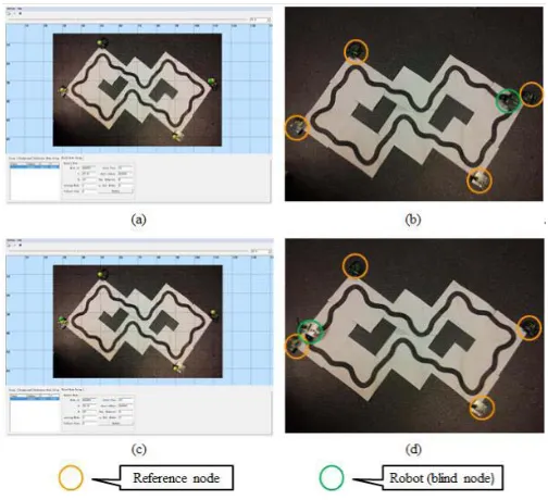
based on the RSSI localization algorithm, a practical test was set up as shown in Figure 9. Four Reference Nodes, with known (X, Y) positions, were deployed in the network and indicated as the yellow circles in the pictures of practical experimental environment, as illustrated in Figure 9(b) and (d). Figure 9(a) illustrates the GUI software at data monitoring centre designed for (b) and (c) for (d).
Fig. 8. (a) Dynamic response of the WSN platform integrated with the optical fiber temperature sensor (FBG2) when it was subjected to different temperature conditions. (b) Dynamic response of the WSN platform when the intrinsic optical fiber pH sensor was subjected to different pH conditions showing the output voltage of the system (corresponding to pH) as a function of time.
Fig. 9. (a) The GUI software at data monitoring center designed for (b) and (c) for (d).
Following that, the blind node sends out a blast of several 1-hop broadcast messages, and any reference node receiving such a message shall make a running average of the
RSSI of the packets received from the targeted blind node. After the broadcast phase, the targeted blind node will send a one-hop unicast message to every reference nodes in radio range requesting the average RSSI calculated during the broadcast blast. The location information of the targeted blind node (the robot position in this test) can then be calculated based on the corresponding physical location information of each reference nodes configured with (X, Y) and RSSI values. When the position of the targeted blind node is calculated, the coordinates of the estimated location can been seen in the GUI software as well as the blind node appearing as a green dot in the background map as shown in Figure 9(a) and (c). The targeted blind node (mobile WSN platform) has been programmed to perform a line tracing exploration strategy, with the real-time estimated location information displayed at the data monitoring centre indicated in Figure 9(a) and (c). When the targeted blind node moves from one reference node (Figure 9(b)) to another (Figure 9(d)), the green dot in the background map of GUI software indicating the targeted blind node moves accordingly as shown in Figure 9(a) and (c) respectively. This positive result illustrates the successful implementation of real-time monitoring and tracking system for wireless mobile platform.
IV. CONCLUSION ANDFUTUREWORK
[image:7.612.48.300.441.671.2]REFERENCES
[1] B. Culshaw, “Optical fiber sensor technologies: Opportunities and-perhaps-pitfalls,” J. Lightw. Technol., vol. 22, no. 1, pp. 39–50, Jan. 2004.
[2] J. Yick, B. Mukherjee, and D. Ghosal, “Wireless sensor network survey,” Comput. Netw., vol. 52, no. 12, pp. 2292–2330, Aug. 2008.
[3] E. O’Connell, M. Healy, S. O’Keeffe, T. Newe, and E. Lewis, “A mote interface for fiber optic spectral sensing with real-time monitoring of the marine environment,” IEEE Sensors J., vol. 13, no. 7, pp. 2619–2625, Jul. 2013.
[4] G. Tuna, V. C. Gungor, and K. Gulez, “An autonomous wireless sensor network deployment system using mobile robots for human existence detection in case of disasters,” Ad Hoc Netw., vol. 13, pp. 54–68, Feb. 2012.
[5] H.-W. Tsai, C.-P. Chu, and T.-S. Chen, “Mobile object tracking in wire-less sensor networks,” Comput. Commun., vol. 30, no. 8, pp. 1811–1825, Jun. 2007.
[6] S. Fu, Z.-G. Hou, and G. Yang, “An indoor navigation system for autonomous mobile robot using wireless sensor network,” in Proc. Int. Conf. Netw., Sens. Control, Mar. 2009, pp. 227–232.
[7] B. Zhou, S. Yang, T. Sun, and K. T. V. Grattan, “A novel wireless mobile platform integrated with optical fibre sensors,” Proc. SPIE, vol. 9157, pp. 1–5, Jun. 2014.
[8] H. J. R. Dutton, Understanding Optical Communications. Englewood Cliffs, NJ, USA: Prentice-Hall, 1998.
[9] N. A. Mohammed, T. A. Ali, and M. H. Aly, “Evaluation and per-formance enhancement for accurate FBG temperature sensor measure-ment with different apodization profiles in single and quasi-distributed DWDM systems,” Opt. Lasers Eng., vol. 55, pp. 22–34, Apr. 2014. [10] T. Hien Nguyen, T. Venugopalan, T. Sun, and K. T. V. Grattan,
“Devel-opment of intrinsic optical fiber pH sensors for industrial applications,” in Proc. IEEE Sensors, Oct. 2009, pp. 89–94.
[11] W. Chen, L. Yua, and Y. Xi, “A review of control and localization for mobile sensor networks,” in Proc. 6th World Congr. Intell. Control Autom., Jun. 2006, pp. 9164–9168.
[12] G. Zanca, F. Zorzi, A. Zanella, and M. Zorzi, “Experimental compar-ison of RSSI-based localization algorithms for indoor wireless sensor networks,” in Proc. RealWSN, 2008, pp. 1–5.
Bochao Zhou received the B.Sc. degree in computer science from the Nanjing Aeronautics and Astronautics University, Nanjing, China, in 2010. He is currently pursuing the Ph.D. degree at the Centre for Instrumentation and Sensors, City University London, London, U.K. His research interests are in the field of wireless sensor network for optical fiber sensors, mobile robots control, and computer networking.
Shuo Yang received the B.Sc. degree in electrical engineering from the Nan-jing Aeronautics and Astronautics University, NanNan-jing, China, in 2010. He is currently pursuing the Ph.D. degree at City University London, London, U.K. His research interests are mainly focused on optical fiber sensor integrated with wireless sensor network-based application and energy harvesting system modeling and control.
Tong Sun received the B.E., M.E., and Dr.Ing. degrees in mechani-cal engineering from the Department of Precision Instrumentation, Harbin Institute of Technology, Harbin, China, in 1990, 1993, and 1998, respec-tively, and the D.Phil. degree in applied physics from City University London, London, U.K., in 1999. From 2000 to 2001, she was an Assis-tant Professor with Nanyang Technological University, Singapore. In 2001, she joined City University London as a Lecturer. Subsequently, she was promoted to Senior Lecturer in 2003, a Reader in 2006, and a Professor in 2008 with City University London.