Rochester Institute of Technology
RIT Scholar Works
Theses Thesis/Dissertation Collections
2-1-1988
A model for non-image area of offset lithographic
process
Vinay Chhajlani
Follow this and additional works at:http://scholarworks.rit.edu/theses
This Thesis is brought to you for free and open access by the Thesis/Dissertation Collections at RIT Scholar Works. It has been accepted for inclusion in Theses by an authorized administrator of RIT Scholar Works. For more information, please [email protected].
Recommended Citation
Certificate of Approval -- Master's Thesis
School of Printing and Management and Sciences Rochester Institute of Technology
Rochester, New York
CERTIFICATE OF APPROVAL
MASTER'S THESIS
This is to certify that the Master's Thesis of
Vinay Chhajlani name of student
with a major in printing Technology
has been approved by the Thesis Committee as satisfactory for the thesis requirement for the Master of Science degree at the convocation of
February 1988 date
Thesis committee : Julius Silver
-:T,....h-e-s-::i-s-A-d-v-i~s-o...r
-Joseph L. Noga
~du~~ pz~gram C~orAinator Miles Southworth
A MODEL FOR NON-IMAGE AREA OF OFFSET LITHOGRAPHIC PROCESS
by
Vinay Chhajlani
A thesis submitted in partial fulfillment of the
requirements for the degree of Master of Science in the
School of Printing Management and Sciences in the College of Graphic Arts and Photography of the
Rochester Institute of Technology
February, 1988
Title of Thesis:
A MODEL FOR NON-IMAGE AREA OF OFFSET LITHOGRAPHIC PROCESS
I, vinay Chhajlani, hereby grant permission to the Wallace Memorial Library, of RIT, to reproduce my thesis in whole or in part. Any reproduction will not be for commercial use or profit.
ACKNOWLEDGEMENTS
I am very thankful to my advisor Dr. J. L. Silver for his
help and guidance in completing this thesis. I am also
thankful to Prof. J. L. Noga for for his advise and
Mr. Frank Cost for being on my thesis committee and his
support on the subject matter I chose. I am grateful to my
wife for her constant support during the entire period of my
thesis work.
TABLE OF CONTENTS
LIST OF FIGURES IV
ABSTRACT v
1. INTRODUCTION 1
2. NEED FOR A MODEL 3
3. THE PHYSICAL MODEL 9
4. DEVELOPING THE MODEL 16
5. CONCLUSION 25
6. RECOMMENDATIONS 28
APPENDIX A 31
APPENDIX B 32
LIST OF FIGURES
Figure 2.1: Model of water flow in an offset unit
Figure 3.1: Diagram showing the plate surface and
the various films present at the plate inking form roller nip.
Figure 4.1: Diagram showing a three phase interface
with respective interfacial tension and contact angle.
Figure 4.2: Diagram showing a three phase interface
with respective interfacial tension and
contact angles where one phase is solid.
Figure A.l: Graphical determination of tolerance range
for the surface properties of the fountain
solution based on Griffith's surface energy
for fracture.
ABSTRACT
Lithography is the most common printing process. However,
very little is known about the theory of lithography.
Pressroom practices have evolved more out of experience than
on the basis of any theory. The objective of this paper is
to develope a mathematical model for the non-image area of
the offset lithographic plate. A model of this kind would
provide a rationalization for the observed behavior in
lithographic process.
The study concentrates on the various materials and the
phenomenons involved. Properties of aluminum oxide surface
and gum arabic that make them suitable for the process have
been presented. Rheological properties of ink have been
discussed to show their effect on the print quality. Most
importantly the subject of surface energetics has been used
to explain the interfacial behavior of the three phases
involed
-ink, fountain solution and plate surface.
The study of the interfacial behavior helps in arriving at
the final model. There are several phenomenon taking place
in making lithography work. Adsorption of gum arabic,
wetting of the plate by fountain solution and film splitting
at the nip exit are explained and the interrelationship
between them derived. Surface energetic equations and
Griffith's free energy for fracture have been usedto present
the final model for the system.
The model as proposed in this paper gives a deeper insight
into the lithographic process and helps- in understanding the
reasons for the printing abberations. There is a need to
model other aspects of the process and design methods to
test them so as to help in development of better equipment
and standard practices for lithography.
CHAPTER I
INTRODUCTION
Lithographic offset printing is the most commonly used
printing process. It is different from the other printing
processes in that the printing plate is planar. There is no
mechanical separation between the image and the non-image
areas instead their delineation is achieved chemically.
Lithography, to a layman, means a process involving two
liquids, ink and fountain solution, that do not mix and two
different surfaces
-1. hydrophilic and oleophobic 2.
hydrophobic and oleophilic. The ink being solvent based gets
attracted to the oleophilic image area and the fountain
solution being an aqueous solution gets attracted to the
hydrophilic non-image areas. This is a very simple
explanation for the theory of lithography but it is not
accurate.
The theory of lithographic offset printing is not well
understood. In the past not much work has been done to
explain the process. In recent years with the growth of the
industry there is a growing interest in the theory of
The lack of theory and well developed mechanisms means that
there is no well marked approach to press room practices.
There is also no set procedure to correcting printing
abberations. Press room practices have evolved more out of
experience than based on any theory. Researchers are now
attempting to explain the mechanism.
The purpose of this thesis is to develope a model for the
non-image area of the plate and the process of keeping the
non image clean. A study and a model of this kind would aid
CHAPTER II
THE NEED FOR A MODEL
The lithographic process is very complex and involves
several variables and mechanisms. Studies have been
conducted to study different aspects of the process. In
order to get a understanding of the process it is very
necessary to understand all the mechanisms and their role in
the process. Theories have been proposed for:
1. Ink transfer mechanism
2. Fountain solution transfer
3. Ink and fountain solution transfer
4. Ink water emulsification
The above mentioned theories are discussed in brief in this
paper. The main mechanism dealt in each is explained along
with the significance and how it helps in understanding
lithography
-INK TRANSFER MECHANISM
Several models have been proposed to calculate ink film
thickness through the various rollers in the inking system,
plate, blanket and the image area on the paper. These models
reasons for ink transfer related problems like ghosting.
There have been studies by Bradford1, Hull2, Mill3
addressing the issue of ink distribution. Guerrette4
has
proposed a model for calculating steady state ink film thickness throughout the inking system.
The method uses inversion of a matrix representing volume
continuity of ink within a roller distribution. It is based on an ink split at each nip and incorporates the effect of
plate coverage on the transfer. Along with the thickness
distribution, the amount of ink contributed to the plate by
each form roller and principal ghost magnitude have been
calculated. It has been shown that thickness distribution on
rollers and contribution by each roller is highly dependent
on the image coverage.
This model based on volume continuity is useful in
understanding ink transfer mechanism. However it gives no
insight to what causes the ink to transfer to the image
areas and not transfer to the non image areas.
FOUNTAIN SOLUTION TRANSFER
Fountain solution flow model has been proposed by Kartunnen
and Lindqvist5. This model gives water flow schematically
only. It does not represent ink and water interaction. The
continuous as a function of time. It also assumes that water
flow is even and equal in all image and non image areas
respectively.
Figure 2. 1 below shows the water flow as proposed by the
authors. Variable Io is the water feed, K]_, K3 , K5, K8, K10
are the evaporation factors in the process and K2, K4, K6,
K7, K9, K^ are the splitting coefficients. X and Y are the
transfer parameters.
Non-image area io
y'o
IN_KER_
W
k7l7>2kil3M
k,IA1!
U=R\
Image area 12
Plate kfil6'2
kcl
t t=
Blanket
kinl/.
Paper 3
Scale
0 1 2 3 U um
Fig. 2.1 Model of water flow in an offset unit
The model also proposes that the most important criterion
for the print quality are the amounts of water transferred
to the image and the non image areas. If too much water is
transferred to the image areas it would result in water
[image:14.513.135.408.272.477.2]areas it would cause scumming. It is very important
therefore that a proper water feed level be maintained to
ensure good print quality.
A simulation program was developed based on the model which
can be used to calculate tolerance limits of water feed
based on relative printing area and interaction parameters.
This model does not however deal with the factors that
affect the water and ink transfer.
INK AND FOUNTAIN SOLUTION TRANSFER
This model also proposed by Kartunnen and Lindqvist6 is a
composite model. It discusses both ink and fountain solution
transfer. An offset unit simulator has been proposed based
on both ink and water transfer. Presence and the effect of
surface water and emulsified water have proposed.
The models described in this chapter provide a understanding
of the quantitative flow. However a study of the factors
that cause this flow is required. The theory of lithographic
printing process is very incomplete. Many press subsystems
like dampening and inking systems designs have evolved over
the years and have been improvised by experience. There is
very little theoretical basis for many designs. Press room
practices have been developed mofe out of experience than
certain operating conditions on the print quality but there
is not much work done to understand the mechanisms. A better
understanding of the mechanism would explain the reason for
the effects of certain conditions on print quality.
The main objective of this thesis is to develop a model for
the lithographic plate non image area at the dampening form
roller
-plate nip and at the inking form roller
-plate
nip. Various phenomena taking place at these two nips are
described in detail. A relationship is developed between
these phenomena which would lead to the model.
This thesis is focused on a conventional lithographic
grained aluminum plate surface, a conventional dampening
References for Chapter II
1. Bradford, Dr. J. R. , 'Lithographic Press Ink Distribution Studies by Radio Tracer Techniques'
, TAGA Proceedings
(1954) , p.279.
2. Hull, H. H. , 'The Theoretical Analysis and Practical Evaluation of Roller Ink Distribution Systems', TAGA
Proceedings (1968) .
3. Mill, C. C, 'An Experimental Test of a Theory of Ink
Distribution', Advances in Printing Sciences and
Technology, Vol. 1 (1961), Ed. by Banks.
4. Guerrette, D. J., 'A Steady State Inking System Model for Predicting Ink Film Thickness Distribution', TAGA Proceedings , p. 404
5. Karttunen, S., Lindqvist, U. , 'Water Flow and Surfactant Effects in Offset Litho Printing', Advances in Printing Science and Technology, Vol. 15, Ed. W. H. Banks
CHAPTER III
THE PHYSICAL MODEL
In lithography, keeping the non image area free of ink is
very critical to the quality of printing. The non image area
is kept clean chemically. In order to arrive at a
mathematical model it is necessary to start with a simple
descriptive model. As a starting point a simple model is
being assumed.
This model assumes that when the plate is "gummed"
before
running the press the porous non image area made of a
grained aluminum surface adsorbs gum arabic. When the
dampening form roller passes over the non image area a water
film is left on it. This happens because the gum arabic
molecules attract the water dipole and hence reduce the
surface tension and so the water spreads on the non image
area. When the inking form roller passes over the image area
there are three different films at the nip. These films are:
1. Water film
2. Ink film
10
At the nip exit a cleavage takes place. The film requiring the minimum force will split. In order to get a clean non
image area, the water film should split. This will happen only when the ink film thickness is such that it requires a
larger force to split than the water film. The composite
film should backtrap onto the ink film on the form roller
and the interfacial tension between the composite film and
water film should be so that there is no split at this
interface.
INK RLrf
XrlAC-,6 A*EA
^ |M|
f
^^-^ / MoN^e^RE*
GRAIHED AUUniHurn
SURFACE
Figure 3. 1 Diagram showing the plate surface and
the various films present at the plate
inking form roller nip.
In order to develop a mathematical model for the non image
area it would be necessary to understand the various
phenomena taking place at the non
image1
areas. It is also
necessary to know the materials involved and their physical,
chemical and interfacial properties. One of the most
11
This chapter concentrates on the materials, their
interaction and the surface phenomena that make lithography
work. The actual mathematical relationships would be derived
based on surface energetics.
ALUMINUM PLATE SURFACE
The conventional lithographic plate is made of anodized
aluminum and has a grained surface. The plate is grained to
give it a large surface area and porosity. The grains serve
two important functions, they help hold the image area
coating in place and the grained surface serves as the non
image area.
Chemical and physical structures of an anodized aluminum
plate have been described in detail by Salgo1. Chemically,
the aluminum plate surface is covered by solid A1203.H20 and
the top layer consists of gamma A1203 crystal grains. The
oxide layer thickness ranges from 5 to 4 0 microns.
When wetted with water, the water content of this oxide
hydrogel depends on the condition under which it was
manufactured. Physically the oxide layer is cellular and
porous2- Its properties depend on the following variables:
pore dimension, cell wall thickness, boundary layer
thickness at the cell bottom, nature of oxide formed and
pore sealing. This microstructure makes the plate surface
12
The wettability of water to this aluminum oxide surface is
increased by adsorption of gum arabic. The type of
adsorption and the factors affecting it are discussed later
in this chapter.
GUM ARABIC ADSORPTION
Gum arabic plays a very important role in keeping the non
image area of a lithographic plate clean. When using
conventional lithography, the plate is usually "gummed"
before starting the press. Gum is also a component of the
fountain solution.
Gum arabic is a natural product obtained from acacia trees.
Chemically it consists of the mixed magnesium and calcium
salts of complex polymeric hydroxiacid3. It has a mean
molecular weight of about 250000. In solution it behaves as
a typical colloidal electrolyte and the free acid, arabic
acid, can be obtained by using an ion exchange column to
remove the cations.
The free acid has an equivalent weight of about 1250. It has
about 2 00 carboxyl groups present per molecule. This means
at very low pH gum arabic solution could cause active
corrosion or dissolution of a metal by the free acids.
The gum arabic molecules are adsorbed by the grained
aluminum. Since gum arabic in solution is a highly hydrated
anion with multiplicity of carboxyl group the sorption would
13
A monolayer of gum arabic adsorbed is enough to make the non
image area hydrophilic i.e. it reduces the surface tension
for the formation of the water film. Contact angle studies
as reported by Adams4
prove that adsorption rates depend on
the concentration and pH of the solution. Contact angle is a
good measure of wettability of a surface by a liquid.
FILM SPLITTING AT NIP EXIT
When the non image area passes under the dampening form
roller a water film forms on it. At the inking form roller
-plate nip there are at least three films present, ink, ink
& water and water film. At the nip exit one of the films or
an interface has to cleave. The force necessary to split a
film between two surfaces is expressed by Stefan's equation:
F = CuVA/t
Where F = force required to split the film
C = constant
u =
viscosity V =
velocity at which parted A = surface area
t = film thickness
If there are two more films then the film requiring the
lesser force will cleave at the cavitation nuclei4.
It can be seen by the above discussions that it is very
important to have a proper plate surface, desired level of
gum adsorption, proper water film thickness, and proper ink
14
There is a need to understand these procedures and their
operating limits.
The main objective in this thesis is to establish the
relationship between these practices and explain the need
for each from a theoretical stand point. These relationships
would be used to derive at a model that would rationalize
15
References for Chapter III
1. Salgo, V., Theoretical principles of the application of
aluminum oxide layers in the printing industry' , APST
Vol.2 (1962) ed. W.Banks, p.235.
2. Severn, I.D., Burring, S.L., 'The wetting properties of litho printing surfaces. 'London:Academic Press(1978)
3. Mantell, C.L., 'Water soluble gums' ,reinhold (1947)
4. Adams, R. A. C. Sorption of Gum arabic from aqueous
solution onto aluminum', Printing technology, Vol.15,
No.2, (1971) , p.24.
5. McPhee, J., 'An engineers analysis of the lithographic
16
CHAPTER IV
Chapter 4: DEVELOPING THE MODEL
Two fields are very important in the study of the theory of
lithography, they are Rheology and Surface energetics.
Rheology helps in understanding the properties and behavior
of ink and surface energetics gives an insight to the
interfacial behavior in the process.
RHEOLOGICAL PROPERTIES OF THE INK
Ink is a non newtonian fluid. It is a solid in liquid
dispersion. The solid is the pigment and the liquid is the
solvent. One of the most important rheological property of
the ink is the tack. Tack of ink is a function of elasticity
and viscosity of the ink. It is very important for the
working of the lithographic process that the ink and the
fountain solution be insoluble in each other but be miscible
with each other.
*-Water take up of ink has been a subject of study in several
experiments. There has been work on water take up of ink
with time and its effect on print quality. Lindqvist has
determined that the emulsification tendency of ink depends
on its viscosity and interfacial tension. A higher viscosity
17
interfacial tension also reduces the total water content,
evidently by decreasing the amount of surface water on the
form rollers2.
The tack of ink-water emulsion is less than that of the ink
on the form rollers. This is also very important because a
low tack ink would trap onto a high tack ink. At the plate
inking form roller nip, water film on the plate comes in
contact with the ink on the form roller. The interfacial
tension should be such that the ink and water are able to
mix to form an emulsion. This emulsion would backtrap onto
the ink on the form roller which is necessary so that no ink
is left on the non image area.3
Ink and water surface
properties are also critical to the process. The next
section concentrates on the surface properties of these two
and the interfacial phenomenon in lithography
-SURFACE ENERGETICS OF LITHOGRAPHY
The most important subjects required to understand the
relationship between the three phase namely plate, ink and
water are surface chemistry and surface energetics. Concepts
of interfacial tension, surface tension and contact angle
should be well understood.
Surface chemistry or the physical chemistry of surfaces is a
science that deals with the study of two or more phases at
their interface. The phases could be
18
liquid, a liquid and a solid, a liquid and a vapor , a
vapor and a solid.
When two phases are brought together so that one would
dissolve in the other they would form a composite single
phase called a solution, an example is when salt is mixed
with water a saline solution is formed. When the two phases
do not form a solution but can be mixed with one phase
finely divided and dispersed in the other, it forms a
dispersion.
In lithography, there are three phases in the non image
area, the plate surface, the fountain solution and the ink.
It is desired that the fountain solution has a greater
affinity for the solid phase as compared to the ink. One of
the measures of affinity is the contact angle between two
surfaces.
Contact angle is the angle that a phase makes with another
at the interface. The contact angle is a good measure of
wettability of a solid phase by a liquid phase. The
properties that determine the contact angle are interfacial
tension and interfacial free energy- Surface tension is
defined as the energy required (work done) to create a unit
area of additional surface. If there are two liquid phases
19
would have more affinity for the solid phase. For example,
when something is greasy water will not stick to it because
water has a greater surface tension than the oil. But whenl
detergent is mixed with water it wets the surface and
replaces the oil because the solid is preferentially wet by
the detergent solution as compared to oil or grease.
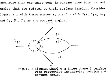
When more than one phase come in contact they form contact
angles that are related to their surface tension. Consider
figure 4.1 with three phases 1, 2 and 3 with #13, ^23' ^12
and !, 2' ^3 as tne contact angles. Y12
23
Fig. 4.1: diagram showing a three phase interface with respective interfacial tension and
contact angle.
When the phases are in a state of equilibrium the three
forces balance themselves.
At the inking form roller
-plate nip the lithographic
process is a special case of this where phase 1 is ink,
[image:28.513.47.465.207.510.2]20
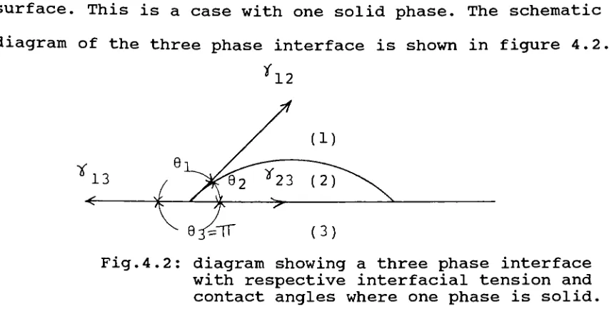
surface. This is a case with one solid phase. The schematic
diagram of the three phase interface is shown in figure 4.2.
*12
Fig.4. 2: diagram showing a three phase interface
with respective interfacial tension and contact angles where one phase is solid.
In this situation the contact angle 03 is equal to 180
degrees due to solid constraint. This schematic will be used
to derive at a model for the non image area of lithographic
plate. In this three phase situation the horizontal forces
balance as:
^
13 =
*
23 +
^12
+ cos2 equation 1where Y = interfacial tension Q = contact angle
There are no direct ways of measuring the interfacial
tensions. However, equations to calculate interfacial
tension between two phases, i and j have been proposed by
Kaeble, Dynes and Pav4.
[image:29.513.44.474.45.265.2]21
where <*= square root
of that part of interfacial
tension due to dispersion type (London)
bonding forces
^<- = square
root of that part of interfacial
tension due to polar type (Keesom)
bonding forces
This equation can be used to calculate the forces knowing
the measurable material properties which are the dispersion
and polar type bonding forces. Appendix A shows calculated
interfacial tension for some common lithographic material
based on equation 2.
Of special interest to lithography is the application of
Griffith fracture theory. Using the theory of fracture the
criteria for failure by crack can be expressed as:
J-c- J-""' TT rt-~
equation 3
where dc= the critical crack propagation stress
c = length of the crack
E =
Young' s modulus
3e> = Griffith's free
energy for fracture
The adhesion of ink and fountain solution to the image or
non image area of the plate is related by the Griffith's
free energy which is defined as follows:
$ = -S2/2 = R2 - Rq2
equation 4
where S2 =
z
22
S2 is the spreading coefficient of the fountain solution.
The spreading coefficient provides a criteria for describing
spontaneous mechanism of bonding and debonding between
phases. If the value of S is greater than or equal to zero
then one phase would bond with the other. Constants R and R0
are derived from the values of =k and > . This relationship
is given by equation 5.
^ ^ 2- ^
Equation 5
Equation 4 defines a circle in the ~6g, <'2, >2 cartesian
space. It can be seen that if R < RO then the spreading
coefficient S2 > 0 which means that phase 2 would debond
phase 1 from phase 3. This is the conditions desired in the
non image area of the lithographic plate. This models the
non image area and describes the properties required in the
three phases, the interaction between the three phase and
the actual process at the inking form roller
-plate nip.
The image area is also described by the same equation when
the spreading coefficient S2 < 0. The circles defined by
equation 4 which give a graphic representation of the
interfacial phenomenon are shown in Appendix II.
A relationship between measurable surface properties of the
23
established with the help of equations 1 to 5. This model
helps in understanding the surface interactions that come
into play in the lithographic printing process. They also
help in graphically establishing a criteria and surface
property tolerance for the ink and fountain solution in the
process.
The discussions and derivations in this chapter have shown
how each phenomenon is important to the success of good
lithographic printing. The study of rheology of ink and the
surface properties of the phases involved lead to the final
model for the process. Studies addressing Gum Arabic
adsorption and contact angle as a measure of wettability and
Griffith theory of fracture by propagation of crack have
24
References for Chapter IV
1. Silver, J., Course Lecture notes from Ink, Color and
Substrates, Spring 86.
2. Lindqvist, U. , 'Ink Emulsification and its Effect on
Print Quality in Offset',Graphic Arts in Finland,
Vol. 5, No. 1 (1976)
3. Silver, J., Course Lecture notes from Ink, Color and
Substrates, Spring 86.
4. Kaelbel, D. H. , Dynes, P. J., and Pav, D. E. , 'Surface
Energetics Analysis of Lithography', Adhesion Science
25
CHAPTER V
CONCLUSION
A model has been proposed in this paper that takes into
account the materials involved and the phenomenon that take
place in the plate
-dampening form roller nip and the plate
-ink form roller nip. emphasis has been placed on the
surface properties of the phase involved. The model was
aimed at giving a better insight into the theory of
lithography.
The model has not been proved through an experiment designed
to test it. The author has instead, in the following
sections, supported the model by the conditions often
reported by the pressmen from their experience of the
lithographic process. Conditions reported by other
researchers in lithography have also been used for this
purpose. These are presented in the appendix section. The
model also provides an explanation for the commonly reported
printing abberations.
One of the most common problems in lithography is scumming.
The causes for scumming could be several as can be seen from
the model. Scumming could result if there is not an optimum
26
area as this would cause the ink film to split at the nip
exit hence causing ink transfer in the non image areas.
Wearing out of gum arabic from the plate surface can also
cause scumming. If the gum wears out it results in increased
interfacial tension between the fountain solution and plate
surface thus affecting the debonding of ink from the non
image area by propagation of crack. This also results in
scumming.
The common practice to start up printing also supports the
model. When a press is started, the dampening form roller is
always dropped onto the plate first and the inking form
roller is dropped only after a film of fountain solution is
formed on the plate surface. If the pressman makes a mistake
and drops the ink roller first, the entire plate surface
gets covered by an ink film. But when the dampening form
roller is dropped the plate starts to clear from the non
image area. This is consistent with the model. This happens
because the non image area has a positive spreading
coefficient for the fountain solution so even if the area is
covered with ink the fountain solution will spontaneously
debond ink from the non image area.
Critical to running of the process is the ink water balance.
The need for this balance also arises from the phenomenon
27
solution necessary for keeping the non image area clean.
There is also a maximum limit on fountain solution feed
above which water mark up of the image area would appear.
The model explains the observed press behavior
qualitatively. A quantitative proof would require the use of
measuring techniques that would enable measuring the values
of key variables on a running press. An understanding of
materials and mechanisms involved and their inter
relationships presented as a mathematical model provides a
rational for the behavior of the non image area in
28
CHAPTER VI
RECOMMENDATIONS
The non image area of a conventional lithographic plate has
been studied in this thesis. There are several other
mechanisms involved in this process. Ther is a need to
understand all of these in greater detail to provide a
complete theory for lithography- Research needs to be done
to develope models for the other mechanisms involved.
Another area of interest is the developement of
instrumentation to aid in verification of the models. A
major difficulty involved in the design of proper measuring
device is the non newtonian nature of ink and its behavior
at high speeds. There is a need for measuring film
thicknesses, ink properties and interfacial properties on a
running press. The dynamic measurements would represent the
true value for the process.
There is a need for a better way to explain the relationship
between ink viscocity, elasticity and the ink tack, limits
on ink tack that would aid in keeping the non image area
29
The model desribed in this paper is specific to a grained
aluminum plate and a conventional dampening system. There
are several other types of plates, fountain solutions and
dampening system in use. Each has its unique properties.
Each of these have to be studied individually to explain the
principles underlying them.
A thechnique that can be very useful in testing the various
models is simulation. A computer program could be designed
to test the model under various conditions by using assumed
realistic values of variables.
Developing models for all the mechanisms and having
techniques to test them would greatly aid in the design of
equipment and would lead to more controlled process. It
would also enable the standardization of press room
30
31 < X 5 2 a a, < 3 v 1 c
1 n r* rt 1 1
3 u 1 1 o o
IN J3
1 1
c c
>0 -H
u u n r- O r% -7
> S 3
J o o
c* C7* CT* 1 1 %o rn
u. to
c c
-H 0
, t1+ . - u
r- vj <Xt r* o
e e 3
n 3 ^H
u o
S n
1 1 O IS
a IS is 1 1 IS
u U. LO
-C
-^ tl
c IS 7 o o o o
C o
u i
c
.-1 o
r- 1 n CT> o ^
IS rM ^
J -H
1- 1-1
u 1 X 1
o*
-* "^ 1
4 U
55 a 1 1 CS
.-i
1 1
o 5 W *< 3
U O i)
4-1 U 1 1
<s r^ en
c to a 1 1 o r>i CM 1 1
*-* 3* *H
CM
-H
2 V n -4 v> ^ c *
0 t-H O* * a en \0 IS
H n o m IA M r* in
j^
U
1 u
Cl
c c U 17*
JK c vO vD -4 < ^ *
W"O I. o
- "-^ 3 CI (W t-4 ** CN vO ** IS \D
3 1 H to. 4 n -1 IS
u o S
S 2. o- (J u
2=* c
CI ? c
t~ u c o
O C_ IN
(j .-i * B .
CO O ><
u u
4 tl vO 00 U"\ t^- r\
O- V
u to o. -o er *J is *a -* -T o
3 V c is CN n ^i - IS IS
m OC -1 o
C
n n C
V u 0
u C -tH c
1? 3 n 0
ci 0 c -*^
t- Of te. V J
< 60 u 3
4
1 -4 *
-^ CI n J O
u bo * C u
u c o n
u E o -^ c **- c V
5 ^ c u C i- r* c
c -^ D ] 3 CI
CI u tl - *J X B
u U > : c *j o
9 fl Jd c
-J i M u
-H .1 C o c 9 u JZ
(Li O. t U I
1
^*"32 5 z w a. < .(BO/u/pJ t- <3J o t-VI 3 0) as -4-4
bJJ c m
c o
t-m ' -u 3 ni Ci ej c CO o in C C4-4 ft i.
CJ ca 1)
o c C
4-* 3
1) o QJ s: CJ *-<
0) x:
o *-* t/1
c o c*-- jC o -4-<4 -4-4 ca CU 4-4 r. 4-4 *** o E 01 n CJ cj 4-* 0) o J= a 4-4 E o a cj
03 ca 4-1
<> e^-Z. T3 J= 3 0)
a. 'JO >
![Figure2. 1 belowshows the water flow asproposed by theauthors.Variable Io is the water feed,K]_,K3 ,K5,K8 ,K10are the evaporation factors in the processand K2 ,K4 ,K6 ,K7,K9, K^are the splitting coefficients.XandY are thetransfer parameters.](https://thumb-us.123doks.com/thumbv2/123dok_us/47166.4261/14.513.135.408.272.477/belowshows-asproposed-theauthors-evaporation-processand-coefficients-thetransfer-parameters.webp)