Rochester Institute of Technology
RIT Scholar Works
Theses
Thesis/Dissertation Collections
12-10-2016
Implementation of the meshed tree algorithm on a
switched network
Kuhu Sharma
Follow this and additional works at:
http://scholarworks.rit.edu/theses
This Thesis is brought to you for free and open access by the Thesis/Dissertation Collections at RIT Scholar Works. It has been accepted for inclusion in Theses by an authorized administrator of RIT Scholar Works. For more information, please [email protected].
Recommended Citation
1
Implementation of the meshed tree algorithm
on a switched network
by
Kuhu Sharma
Committee members:
Prof. Nirmala Shenoy
Prof. Bruce Hartpence
Prof. Daryl Johnson
Prof: Bill Stackpole
Thesis submitted in partial fulfillment of the requirements for the
degree of Master of Science in Networking and Systems Administration
Rochester Institute of Technology
B. Thomas Golisano College
of
Computing and Information Sciences
Department of Information Sciences and Technologies
2
Rochester Institute of Technology
B. Thomas Golisano College
of
Computing and Information Sciences
Master of Science in Networking and Systems Administration
Project Approval Form
Student Name: Kuhu Sharma
Thesis Title: Implementation of the meshed tree algorithm on a switched network
Thesis Committee
Name Signature Date
Nirmala Shenoy
Chair
Bruce Hartpence
Committee Member
Daryl Johnson
Committee Member
Bill Stackpole
3
Contents
1. Abstract ... 4
2. Introduction ... 7
3. Purpose ... 8
4. Background ... 8
4.1 Spanning Tree Protocol ... 8
4.2 Rapid Spanning Tree Protocol ... 11
4.2.1 Initial Convergence with RSTP ... 12
4.2.2 Link failure with RSTP ... 15
4.2.3 Root failure with RSTP... 15
4.3 TRansparent Interconnection of Lots of Links (TRILL) ... 17
4.4 Meshed Tree Protocol and Meshed Tree Algorithm ... 17
4.4.1 Protocol operation ... 18
5. Research work and Methodology ... 21
5.1 RSTP model ... 21
5.1.1 RSTP Metrics ... 21
5.1.2 RSTP Topologies ... 22
5.1.3 RSTP results ... 25
5.1.3.1 Topology 1 ... 25
5.1.3.2 Topology 2 ... 32
5.1.3.3 Topology 3
... 35
5.1.3.4 Topology 4 ... 38
5.1.4.5 Consolidated results... 49
5.1.4.6 Analysis ... 49
5.2 MTP implementation ... 50
4
5.2.2 Frame formats ... 51
5.2.3 State diagram and state definitions ... 53
5.2.4 Results ... 56
5.2.5 Analysis ... 56
6. Conclusion ... 57
7. Directions for further research ... 57
8. References ... 58
9. Appendix ... 60
[image:5.612.71.543.360.660.2]Figures
FIGURE 1: Topology with one physical loop ... 9
FIGURE 2: Two possible ways to create a loop-free logical topology with STP ... 9
FIGURE 3: STP port states [9] ... 10
FIGURE 4: Port Transition Sequence [11] ... 11
FIGURE 5: Flag bits and their use in RSTP BPDU [9] ... 12
FIGURE 6: Simple 4 switch topology ... 12
FIGURE 7: RSTP Synchronization between S1 and S2 ... 13
FIGURE 8: Resolved Topology... 14
FIGURE 9: Convergence process when S2 or S4 lose the root port ... 15
FIGURE 10: RSTP root failure resolution... 16
FIGURE 11: MTP Resolution - VID advertisements sent by Root ... 18
FIGURE 12: MTP Resolution- VID table of S3 ... 19
FIGURE 13: MT_VIDs for each switch in the topology ... 20
5
FIGURE 15:
5 node - 2 loop topology... 23
FIGURE 16:
7 node - 3 loop topology... 24
FIGURE 17:
15 node - multiple loop topology ... 24
FIGURE 18: 3 node - 1 loop topology... 25
FIGURE 19: 3 node- 1 loop topology in OPNET- Initial loop resolution ... 26
FIGURE 20: Topology resolution after link between BRIDGE 4 and BRIDGE 5 fails ... 26
FIGURE 21: Topology resolution after root
(BRIDGE 4) fails
... 26
FIGURE 22: 5 node - 2 loop topology... 32
FIGURE 23: 5 node - 2 loop topology in OPNET- Initial loop resolution... 32
FIGURE 24: Topology resolution after link between BRIDGE 4 and BRIDGE 5 fails ... 33
FIGURE 25: Topology resolution after root (BRIDGE 4) fails ... 33
FIGURE 26: 7 node - 3 loop topology... 35
FIGURE 27: 7 node - 3 loop topology in OPNET- Initial loop resolution... 36
FIGURE 28: Topology resolution after link between BRIDGE 4 and BRIDGE 5 fails ... 37
FIGURE 29: Topology resolution after root (BRIDGE 4) fails ... 37
FIGURE 30: 15 node - multiple loop topology ... 38
FIGURE 31: 15 node- mulitple loop topology in OPNET- Initial loop resolution- Scenario 1 ... 39
FIGURE 32: Topology resolution after link failure- Scenario 1 ... 40
FIGURE 33: Topology resolution after root failure- Scenario 1 ... 40
FIGURE 34: 15 node- multiple loop topology in OPNET- Initial loop resolution- Scenario 2 ... 42
FIGURE 35: Topology resolution after link failure- Scenario 2 ... 43
FIGURE 36: Topology resolution after root failure- Scenario 2 ... 43
6
Tables
TABLE 1: Initial Convergence - 3 nodes ... 31
TABLE 2: Link and Root Failure- 3 nodes ... 31
TABLE 3: Initial Convergence ... 34
TABLE 4: Link and Root Failure ... 34
TABLE 5: Initial Convergence ... 37
TABLE 6: Link and Root Failure ... 38
TABLE 7: Initial Convergence ... 41
TABLE 8: Link and Root Failure ... 41
TABLE 9: Initial Convergence ... 48
TABLE 10: Link and Root Failure ... 48
TABLE 11: Metrics from all the RSTP topologies ... 49
TABLE 12: Practical Convergence from all the RSTP topologies... 49
7
1. Abstract
Loop avoidance is a critical component of switched networks. Protocols like STP, RSTP, TRILL,
etc solve this problem in different ways, but there is room for improvement. The Meshed Tree
Protocol aims to improve the performance of switched networks while avoiding loops. In this
research, a working model of the Meshed Tree Protocol (MTP) using OPNET was created. The
performance of RSTP, the current industry standard, was examined and performance metrics like
link failure convergence time and root failure convergence time were documented to create a
baseline for further development of MTP.
2. Introduction
Switched networks introduce link redundancy in order to improve network reliability. However,
this results in loops in the networks which can result in broadcast storms that render the network
unusable. For this reason, protocols like Spanning Tree Protocol (STP) were developed to ensure
loop free forwarding. Loop-avoidance protocols create loop-free forwarding paths by creating
logical trees in the network in such a way that every node is included but there is only one way to
get to each node from every other node. This is done by logically blocking some of the redundant
paths. While this method creates a usable tree topology, it has some inherent problems like
suboptimal path for frame forwarding and convergence times upon link and node failure. RSTP,
the current industry standard for loop resolution, was designed as an improvement to STP, in order
to decrease convergence times on link/node failure. While it was a great improvement over STP,
it does not meet the needs of today’s networks. Hence, complex implementations based on Link
State routing are being considered in Shortest Path Bridging [1] and TRILL [2].
8
tree. This will result in a more optimal path selection, especially for unicast frame forwarding.
Also, since backup paths are readily available, convergence times can be reduced.
3. Purpose
This research is aimed at applying the concept of Meshed Tree Algorithm (MTA) to the switched
network to develop a protocol for loop avoidance, in order to decrease convergence time, failover
time and improve path selection, which will result in an increase in overall reliability and
performance of the network. This protocol is called the Meshed Tree Protocol (MTP).
4. Background
Switched networks are frequently built with redundant links for increased reliability of data
transfer, especially in the case of link failures. This kind of topology creates loops in the networks
and when a broadcast frame is sent out, it can circulate in the network for ever, consuming the
bandwidth and eventually causing the devices to crash. This condition is referred to as a broadcast
storm. To avoid such an occurrence, protocols are implemented which create a loop-free logical
topology over a physical topology with redundant links. This section gives an overview of the
existing solutions to this problem and our proposed solution. Section 3.1 covers Spanning Tree
Protocol (STP), which is based on the Spanning Tree Algorithm. Section 3.2 introduces Rapid
Spanning Tree Protocol (RSTP), an enhancement to STP, which also uses STA. Section 3.3 covers
TRILL, a protocol that is based on linked state routing. Section 3.4 discusses the Meshed Tree
Algorithm and the Meshed Tree Protocol, which is the basis of this research.
4.1 Spanning Tree Protocol
9
ports on switches in the network, such that there is only one logical path between any two switches
at a given time. This is accomplished by creating a logical tree that spans every switch on the
network.
First a root switch is elected and then STP uses the STA algorithm to compute best paths from
every switch to the root switch. Ports that do not lead to the best path (to the root) are blocked.
This creates a single logical path between any two switches. FIGURE 1 shows a topology with a
single loop and FIGURE 2 illustrates two possible ways to construct a logical topology with STP.
FIGURE 1: Topology with one physical loop
10
If any active link fails, the tree is recomputed and the redundant link becomes the active link (a
blocked port becomes a forwarding port). This activity is governed by several timers. Switches
running STP exchange control messages called BPDUs (Bridge Protocol Data Units) as a
keep-alive mechanism. These messages are exchanged every 2 seconds (hello time). Topology Change
Notifications (TCNs) are sent if a link failure is detected. TCNs force the MAC address table
entries to age out faster so that the switches can learn them again and make any necessary topology
changes. Once a TCN is received, a blocked port may go through listening and learning stages
before it is ready to forward traffic. Each stage has a timer associated with it, called the forward
delay. By default, this value is 15 seconds. Thus, once link failure is detected a port can move to
the forwarding state in 30 seconds. However, some network failures can only be detected by the
absence of BPDUs. BPDUs have a maximum age time 20 seconds, which means the overall
process will now take about 50 seconds. This is a significant delay for today’s networks. FIGURE
[image:11.612.111.494.418.636.2]3 shows the STP port states and FIGURE 4 shows the transition sequence with timers.
11
FIGURE 4: Port Transition Sequence [11]
4.2 Rapid Spanning Tree Protocol
STP was designed at the time when a minute or so of network downtime was considered
acceptable. However, network uptime expectations changed rapidly as more critical and time
sensitive information traversed through LANs. STP’s network convergence after link
failure/recovery was no longer acceptable. While it was possible to make small improvements in
the performance of STP by manipulating some of the default STP parameters, it became obvious
that significant changes to the way the protocol works would be needed to get major performance
improvements.
The motivation behind RSTP was to make these changes to the way STP worked while keeping
the same plug and play functionality offered by STP. RSTP uses most of the same terminology
and is also designed to be backwards compatible with STP.
In RSTP, port states and port roles have been decoupled. Port states are discarding, learning,
forwarding.
Port roles are root, designated, backup (previously blocking) and alternate (previously blocking).
12
FIGURE 5: Flag bits and their use in RSTP BPDU [9]
4.2.1 Initial Convergence with RSTP
Let us consider this 4 switch topology in FIGURE 6. For initial convergence, root has to be elected.
Here S1 will eventually be the root.
FIGURE 6: Simple 4 switch topology
13
proposal flag set. Let’s consider the link between S1 and S2. Both switches send a BPDU with the
proposal flag set. Since the S1 sends a superior BPDU (S1 has a lower bridge ID), S2 accepts S1
as the root and sends an acknowledgement BPDU with the agreement bit set. S2 then sets port 1
to be root port (and removes root port role from any other port that may have had it, making it
designated discarding). S2 also puts port 2 (and in general, all other non-edge designated ports)
into discarding state. Once all the other ports (in this case port 2) are in discarding state, S2 will
now move port 1 into forwarding state and send out a response BPDU with the agreement flag set.
After that, port 2 on S2 reaches designated forwarding state. This completes the RSTP
synchronization process between S1 and S2. FIGURE 7 illustrates this process.
FIGURE 7: RSTP Synchronization between S1 and S2
14
a superior BPDU (where S1 is the root). This causes S3 to change its root port to port 1. At the
same time S4 also learns that S1 is the root through the same synchronization process. Thus the
topology can converge much faster than it did with STP, where ports had to cycle through the
listening-learning-forwarding states, with each transition adding a delay of 15 seconds.
Although this is a huge improvement over STP, for larger topologies time to converge will go up
because a lot of potential roots will be established during the synchronization process, that have to
be renegotiated before the final convergence. MTP aims to remove this trial and error process.
Topology change is detected faster in RSTP than in STP, due to the keep-alive mechanism. Hello
BPDUs are sent every 2 seconds by default. 3 missed hellos are considered a failure in the
topology. Physical link failures are detected instantly, i.e. 3 missed hellos are not required.
For ports that are not part of the active topology, RSTP uses the concepts of alternate ports and
backup ports. An alternate port is the next best way to get to the root, if the root becomes
unavailable through the root port. A backup port acts as a backup for the designated port on the
same segment (not very common in today’s networks). FIGURE 8 shows the final resolution of
the above topology.
15
4.2.2 Link failure with RSTP
Now let us assume that the link between S2 and S3 fails. S3 has now lost its root port but it has an
alternate port which can be quickly transitioned to forwarding state to reconverge the topology.
The alternate port allows the alternate path to be established quickly. However, this is only true
for S3. If S2 or S4 were to lose their root port, the topology must reconverge, as seen in FIGURE
9. Also, the alternate path will only come into play when the primary path is disabled. This is
suboptimal because all the links are not used effectively. With MTP, all paths are in use and frames
will simply choose the best path.
FIGURE 9: Convergence process when S2 or S4 lose the root port
4.2.3 Root failure with RSTP
16
BPDU but S3 gets the proposal from S4 first. At this point S3 still thinks that S1 is the root and
sends this information to S4. S4 will accept this information. After this S2 and S3 will negotiate
root and S2 will be accepted as root by S3. S3 will then relay this information to S4. This process
is illustrated in FIGURE 10 below.
17
The drawback here is that the topology goes through another trial and error process before the new
root is elected. This causes a delay in network convergence.
4.3 TRansparent Interconnection of Lots of Links (TRILL)
TRansparent Interconnection of Lots of Links or TRILL [2] uses the concepts of layer 3 routing
to create a loop free network. This is achieved by encapsulating Ethernet frames in a TRILL
header, which consists of ingress nickname, egress nickname, hop count and multi-destination
flag. This encapsulated frame is then routed using IS-IS to achieve loop avoidance. TRILL reduces
convergence times and avoids packet looping by relying on hop count while the network
transitions. However, this process of using a layer 3 protocol causes more control overhead in the
network.
4.4 Meshed Tree Protocol and Meshed Tree Algorithm
To achieve the performance requirements of today’s networks a faster more robust method of loop
resolution is needed. The Meshed Tree Protocol (MTP) researched here overcomes the
performance challenges of the options discussed above. MTP can achieve much shorter failover
times once the failure has been discovered, with very little control overhead. At the crux of this
protocol is the Meshed Tree Algorithm (MTA).
18
multiple paths to the root, use the best possible path for data transfer, and quickly resolve to the
next available path in case of failure in the network.
4.4.1 Protocol operation
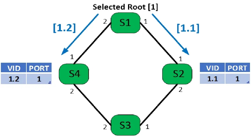
[image:19.612.89.524.387.624.2]Let us look at the same 4 switch topology from FIGURE 6. We consider a single root scenario at
this time. Here, for the sake of simplicity and without loss of generality, we will consider the
BridgeID of S1 to be 1. Since S1 is the administratively selected root, it sends out VID
advertisements to S2 and S4. A VID advertisement is a frame the contains information about one
of the meshed trees. When a VID advertisement is accepted by a switch, an MT_VID is added to
the VID table of the switch. The VID advertisement from the root is a combination of the BridgeID
and port that this advertisement was sent out on. Thus S2 receives [1.1] and S4 receives [1.2].
These advertisements are accepted into the VID tables of switches S2 and S4 (see FIGURE 11).
Note that the VID table also records the incoming port of the MT_VID.
19
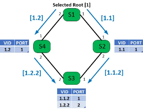
[image:20.612.74.537.198.555.2]S2 and S4 now send VID advertisements to S3, appending the exit port number in the VID
advertisement. Thus, S4 sends [1.2.2] and S2 sends [1.1.2]. The key point here is that S3 accepts
both these VIDs as alternate paths to the root and becomes the first node to become part of multiple
trees in the same physical topology. The VID table of S3 can be seen in FIGURE 12 below.
FIGURE 12: MTP Resolution- VID table of S3
20
FIGURE 13: MT_VIDs for each switch in the topology
Thus we can see that each switch has well established alternate paths which can be used to optimise
transmission of frames. Another important piece of the operation is that the SAT is not populated
in the traditional way, by looking at the source of incoming traffic. Switches in MTP share
information about hosts that are directly connected and this information is saved in Virtual SAT
or a VSAT. This piece is critical to path optimization, because each switch is aware of the switch
MT_VIDs that map to a host and can choose the best possible path to reach the host.
21
active topology. Tha MAC address of a host directly connected to a switch is learned using the
source address of the frame- much like in 802.1D. Once a host is recorded by the switch it is
directly connected to, the switch adds this information into its VSAT table and sends a VSAT
update to its neighbors. the VSAT update contains the host MAC address and the MT_VIDs of the
switch that this host is on. This information is further propagated until all switches know about all
hosts.
5. Research work and Methodology
In this thesis I have researched the operational specifications of RSTP, the current industry
standard, and modeled the behavior of MTP discussed above, using OPNET. OPNET is a suite of
protocols and technologies to design. model and analyse networks.
5.1 RSTP model
I have studied the inbuilt OPNET model demonstrating RSTP and derived important metrics from
this model. OPNET models are developed in consultation with equipment vendors and model the
switch/protocol operation to specification.
5.1.1 RSTP Metrics
The following metrics have been collected:
Initial convergence time
– When all ports are characterized as root/designated/alternate ports and
have reached steady state. Initial convergence time represents the time taken for RSTP to converge
the network before frame forwarding can begin, without loops. In OPNET, this is recorded as the
time-stamp at which the last port state change takes place after the simulation starts.
Link failure and Recovery
22
network and network downtime as a result of a failed link. In OPNET, we recorded this as
the difference between the time at which the last port state change took place after failover
and the time at which link failure occurred.
2.
Link Recovery Convergence Time
– The time at which all ports reach steady state after
the failed link has recovered. When a failed link recovers, the topology must reconverge to
account for this new link. This event would result in a network downtime, which is
recorded by the link recovery convergence time. This metric can also be considered as the
time to converge after the addition of a new link in the network. In OPNET, we recorded
this as the difference between the time at which the last port state change takes place after
recovery and the time at which link recovery took place..
Root failure
1.
Root failure detection time
- The time at which the topology detects a root failure. Root
failure is expected to result in a significant network downtime since a new root must be
calculated. In OPNET this metric is recorded as the difference between time at which the
first state change of a port occurs after root failure and the time at which the root failure
occurs.
2.
Root failure convergence time
- The time at which all ports have reached steady state
again, after root failure (this includes root failure detection time). In OPNET, this is
recorded as the difference between the time at which the last port state change takes place
after root failure and the time at which root failure occurs.
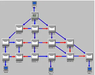
5.1.2 RSTP Topologies
23
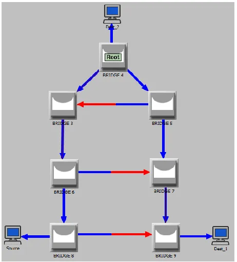
Topology 1: 3 node - 1 loop topology
FIGURE 14: 3 node - 1 loop topology
Topology 2: 5 node - 2 loop topology
24
Topology 3: 7 node - 3 loop topology
FIGURE 16: 7 node - 3 loop topology
Topology 4: 15 node - multiple loop topology
.
25
5.1.3 RSTP results
Parameters
All links are of equal cost- 100BaseT links.
All links are full duplex.
Bridge priority has been set to 0 for all bridges. Thus, Bridge ID depends on the mac address.
Results were calculated for the following seed values- 97, 101, 103, 107, 109.
5.1.3.1 Topology 1
3 node - 1 loop topology
FIGURE 18: 3 node - 1 loop topology
Here we consider the simplest possible topology with 3 nodes and 1 loop, as shown in FIGURE
18. In the OPNET topology below in FIGURE 19, Bridge 4 is the root with initial loop resolution
26
FIGURE 19: 3 node- 1 loop topology in OPNET- Initial loop resolution
Link between Root and Bridge 5 fails at 100 sec and recovers at 200 sec. Bridge 4 (Initial Root)
fails at 300 sec. FIGURE 20 and FIGURE 21 below show topology resolution in each case.
FIGURE 20: Topology resolution after link
between BRIDGE 4 and BRIDGE 5 fails
27
Results
Process for collecting results: The OPNET simulation is run for 500 sec for different seed values.
Every time a port changes state, a time-stamped statement is written to the output file. We take
note of the time stamp for the last state change in the topology, following the events of link failure
at 100 sec, link recovery at 200 sec and root failure at 300 sec. The complete output for each
simulation can be found in Appendix (A).
The following output snippet shows Initial Convergence Time:
|---|
State of Port number 2 for BRIDGE 4 being set to FORWARDING at 0.000036
State of Port number 1 for BRIDGE 4 being set to FORWARDING at 0.000046
State of Port number 3 for BRIDGE 3 being set to BLOCKING at 0.000046
State of Port number 2 for BRIDGE 5 being set to LEARNING at 15.000026
State of Port number 2 for BRIDGE 5 being set to FORWARDING at 30.000026
[Link Failure at 100 sec]
State of Port number 1 for BRIDGE 4 being set to DISABLED at 100.000000
State of Port number 1 for BRIDGE 5 being set to DISABLED at 100.000000
|---|
Here we can see that after the simulation started, the last state change was at 30.000026 sec. After
this, there are no further changes to the port states until the next disruptive event. Thus we are
recording 30.000026 sec as the initial convergence time.
Note here that Port 3 on Bridge 3 is the Alternate Port and was moved to BLOCKING at 0.000046
sec. Thus, this port did not participate in the RSTP Synchronization process and port 2 on Bridge
28
between Bridge 3 and Bridge 5 is not part of the active topology, actual traffic is not impacted by
the slow resolution of port 2 on Bridge 5. Thus we can say that practical convergence time is
0.000046 sec, since frame forwarding can begin at this time.
The following output snippet shows Link Failure Convergence Time:
|---|
State of Port number 1 for BRIDGE 5 being set to DISABLED at 100.000000
State of Port number 3 for BRIDGE 3 being set to LISTENING at 104.000026
State of Port number 3 for BRIDGE 3 being set to FORWARDING at 104.000058
[Link recovers at 200 sec]
State of Port number 1 for BRIDGE 4 being set to LISTENING at 200.000000
|---|
Here we can see that after the link was failed at 100 sec, the last state change was at 104.000058
sec. After this, there are no further changes to the port states until the next disruptive event. Thus
we are recording 4.000058 sec as the Link Failure Convergence Time.
The following output snippet shows Link Recovery Convergence Time:
|---|
State of Port number 1 for BRIDGE 4 being set to LISTENING at 200.000000
State of Port number 1 for BRIDGE 5 being set to LISTENING at 200.000000
State of Port number 2 for BRIDGE 5 being set to LISTENING at 200.000016
29
State of Port number 3 for BRIDGE 3 being set to BLOCKING at 200.000032
State of Port number 1 for BRIDGE 4 being set to FORWARDING at 200.000036
State of Port number 2 for BRIDGE 5 being set to LEARNING at 215.000016
State of Port number 2 for BRIDGE 5 being set to FORWARDING at 230.000016
[Root fails at 300 sec]
State of Port number 2 for BRIDGE 3 being set to LISTENING at 304.000016
|---|
Here we can see that after the link recovers at 200 sec, the last state change was at 230.000016 sec.
After this, there are no further changes to the port states until the next disruptive event. Thus we
are recording 30.000016 sec as the Link Recovery Convergence Time.
as the link recovers, there is now, once again, a loop in the network. Thus port 3 on BRIDGE 3
goes into blocking state and does not participate in RSTP synchronization. This causes port 2 on
BRIDGE 5 to go through the listening-learning-forwarding process. However, this does not impact
actual traffic and frame forwarding can begin at 200.000036 seconds. Hence practical convergence
time is 0.000036 sec.
The following output snippet shows Root Failure Detection Time:
|---|
State of Port number 2 for BRIDGE 5 being set to FORWARDING at 230.000016
[Root fails at 300 sec]
State of Port number 2 for BRIDGE 3 being set to LISTENING at 304.000016
State of Port number 3 for BRIDGE 3 being set to FORWARDING at 304.000016
30
State of Port number 2 for BRIDGE 3 being set to FORWARDING at 334.000016
|---|
Here we can see that after the root fails at 300 sec, the first state change was at 304.000016 sec.
Thus we are recording 4.000016 sec as the Root Failure Detection Time.
The following output snippet shows Root Failure Convergence Time:
|---|
State of Port number 2 for BRIDGE 5 being set to FORWARDING at 230.000016
[Root fails at 300 sec]
State of Port number 2 for BRIDGE 3 being set to LISTENING at 304.000016
State of Port number 3 for BRIDGE 3 being set to FORWARDING at 304.000016
State of Port number 2 for BRIDGE 3 being set to LEARNING at 319.000016
State of Port number 2 for BRIDGE 3 being set to FORWARDING at 334.000016
|---|
Here we can see that after the root fails at 300 sec, the last state change was at 334.000016 sec.
After this, there are no further changes to the port states for the rest of the simulation. Thus we are
recording 34.000016 sec as the Root Failure Convergence Time.
However, port 2 on BRIDGE 3 is facing the root that is now disabled. So it cannot complete the
RSTP synchronization and must cycle through the listening-learning-forwarding process. this
delay does not impact actual traffic and frame forwarding can resume at 304.000016 seconds.
31
Results
S. No
SEED
Initial Convergence Time
1
97
30.000026
2
101
30.000026
3
103
30.000026
4
107
30.000026
5
109
30.000026
TABLE 1: Initial Convergence - 3 nodes
S.
No
SEED
Link Failure
Convergence
Time
Link Recovery
Convergence
Time
Root Failure
Detection Time
Root Failure
Convergence
Time
1
97
4.000058
30.000016
4.000016
34.000016
2
101
4.000058
30.000016
4.000016
34.000016
3
103
4.000058
30.000016
4.000016
34.000016
4
107
4.000058
30.000016
4.000016
34.000016
5
109
4.000058
30.000016
4.000016
34.000016
32
5.1.3.2 Topology 2
5 node - 2 loop topology
FIGURE 22: 5 node - 2 loop topology
In FIGURE 22 we consider a slightly more complex topology, with 5 nodes and 2 loops. In the
OPNET topology below (FIGURE 23), Bridge 4 is the root with initial loop resolution depicted.
The ports in red are the blocked ports.
33
Link between Root and Bridge 5 fails at 100 sec and recovers at 200 sec. Bridge 4 (Initial Root)
fails at 300 sec. FIGURE 24 and FIGURE 25 below show topology resolution in each case.
FIGURE 24: Topology resolution after link
between BRIDGE 4 and BRIDGE 5 fails
34
Results
S. No
SEED
Initial Convergence Time
1
97
30.000056
2
101
30.000056
3
103
30.000056
4
107
30.000056
5
109
30.000056
TABLE 3: Initial Convergence
S.
No
SEED
Link Failure
Convergence
Time
Link Recovery
Convergence
Time
Root Failure
Detection Time
Root Failure
Convergence
Time
1
97
4.000074
30.000016
4.000016
48.000016
2
101
4.000074
30.000016
4.000016
48.000016
3
103
4.000074
30.000016
4.000016
48.000016
4
107
4.000074
30.000016
4.000016
48.000016
5
109
4.000074
30.000016
4.000016
48.000016
35
5.1.3.3 Topology 3
7 node - 3 loop topology
FIGURE 26: 7 node - 3 loop topology
A 7 node - 3 loop topology is considered here. In the OPNET topology below, Bridge 4 is the
36
FIGURE 27: 7 node - 3 loop topology in OPNET- Initial loop resolution
Link between Root and Bridge 5 fails at 100 sec and recovers at 200 sec. Bridge 4 (Initial Root)
37
FIGURE 28: Topology resolution after link
between BRIDGE 4 and BRIDGE 5 fails
FIGURE 29: Topology resolution after root
(BRIDGE 4) fails
Results
S. No
SEED
Initial Convergence Time
1
97
30.000036
2
101
30.000036
3
103
30.000036
4
107
30.000036
5
109
30.000036
38
S.
No
SEED
Link Failure
Convergence
Time
Link Recovery
Convergence
Time
Root Failure
Detection Time
Root Failure
Convergence
Time
1
97
10.000046
30.000016
4.000016
49.000016
2
101
10.000046
30.000016
4.000016
49.000016
3
103
10.000046
30.000016
4.000016
49.000016
4
107
10.000046
30.000016
4.000016
49.000016
5
109
10.000046
30.000016
4.000016
49.000016
TABLE 6: Link and Root Failure
5.1.3.4 Topology 4
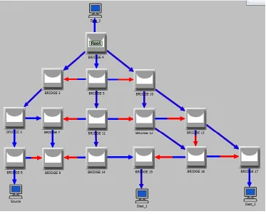
15 node - multiple loop topology
39
Here we consider a large and complex topology with multiple loops to be resolved. In the
OPNET topology below, Bridge 4 is the root with initial loop resolution depicted. The ports in
red are the blocked ports.
For this topology 2 scenarios are considered.
[image:40.612.120.493.251.551.2]Scenario 1: Bridge 5 is the next root
FIGURE 31: 15 node- mulitple loop topology in OPNET- Initial loop resolution- Scenario 1
Link between Root and Bridge 5 fails at 100 sec and recovers at 200 sec. Bridge 4 (Initial Root)
40
FIGURE 32: Topology resolution after link failure- Scenario 1
41
Results: Scenario 1
S. No
SEED
Initial Convergence Time
1
97
32.000026
2
101
32.000026
3
103
32.000026
4
107
32.000026
5
109
32.000026
TABLE 7: Initial Convergence
S.
No
SEED
Link Failure
Convergence
Time
Link Recovery
Convergence
Time
Root Failure
Detection Time
Root Failure
Convergence
Time
1
97
43.000036
30.000062
4.000026
47.000036
2
101
43.000036
30.000062
4.000026
47.000036
3
103
43.000036
30.000062
4.000026
47.000036
4
107
43.000036
30.000062
4.000026
47.000036
5
109
43.000036
30.000062
4.000026
47.000036
42
[image:43.612.144.470.132.388.2]Scenario 2: Bridge 15 is the next root
FIGURE 34: 15 node- multiple loop topology in OPNET- Initial loop resolution- Scenario 2
Link between Root and Bridge 5 fails at 100 sec and recovers at 200 sec. Bridge 4 (Initial Root)
fails at 300 sec. The figures below show topology resolution in each case.
43
FIGURE 35: Topology resolution after link failure- Scenario 2
44
Results: Scenario 2
Output snippet for Initial Convergence Time:
State of Port number 3 for BRIDGE 14 being set to FORWARDING at 3.000026
State of Port number 4 for BRIDGE 12 being set to FORWARDING at 3.000036
State of Port number 2 for BRIDGE 5 being set to LEARNING at 15.000036
State of Port number 3 for BRIDGE 16 being set to LEARNING at 15.000036
State of Port number 3 for BRIDGE 12 being set to LEARNING at 15.000036
State of Port number 3 for BRIDGE 5 being set to LEARNING at 15.000046
State of Port number 3 for BRIDGE 11 being set to LEARNING at 15.000046
State of Port number 2 for BRIDGE 8 being set to LEARNING at 17.000026
State of Port number 2 for BRIDGE 5 being set to FORWARDING at 30.000036
State of Port number 3 for BRIDGE 16 being set to FORWARDING at 30.000036
State of Port number 3 for BRIDGE 12 being set to FORWARDING at 30.000036
State of Port number 3 for BRIDGE 5 being set to FORWARDING at 30.000046
State of Port number 3 for BRIDGE 11 being set to FORWARDING at 30.000046
State of Port number 2 for BRIDGE 8 being set to FORWARDING at 32.000026
[Link failed at 100 sec]
State of Port number 2 for BRIDGE 4 being set to DISABLED at 100.000000
Thus, Initial Convergence Time is 32.000026 seconds. However some ports go through the
45
ports. This does not impact traffic, because frame forwarding is possible at this time. Thus
practical convergence time is 3.000036 sec.
Output snippet for Link Failure Convergence Time:
State of Port number 3 for BRIDGE 9 being set to LISTENING at 113.000036
State of Port number 1 for BRIDGE 14 being set to BLOCKING at 113.000052
State of Port number 1 for BRIDGE 10 being set to LEARNING at 119.000016
State of Port number 1 for BRIDGE 7 being set to LEARNING at 125.000026
State of Port number 2 for BRIDGE 12 being set to LEARNING at 125.000026
State of Port number 1 for BRIDGE 15 being set to LEARNING at 128.000016
State of Port number 3 for BRIDGE 9 being set to LEARNING at 128.000036
State of Port number 1 for BRIDGE 10 being set to FORWARDING at 134.000016
State of Port number 1 for BRIDGE 7 being set to FORWARDING at 140.000026
State of Port number 2 for BRIDGE 12 being set to FORWARDING at 140.000026
State of Port number 1 for BRIDGE 15 being set to FORWARDING at 143.000016
State of Port number 3 for BRIDGE 9 being set to FORWARDING at 143.000036
[Link recovered at 200 sec]
State of Port number 2 for BRIDGE 4 being set to LISTENING at 200.000000
Since the link failed at 100 sec, Link Failure Convergence Time is 43.000036. However, for the
46
Output snippet for Link Recovery Convergence Time and Root Failure Detection Time:
State of Port number 2 for BRIDGE 15 being set to BLOCKING at 200.000078
State of Port number 3 for BRIDGE 14 being set to FORWARDING at 200.000103
State of Port number 3 for BRIDGE 5 being set to LEARNING at 215.000016
State of Port number 2 for BRIDGE 5 being set to LEARNING at 215.000016
State of Port number 1 for BRIDGE 11 being set to LEARNING at 215.000046
State of Port number 3 for BRIDGE 11 being set to LEARNING at 215.000046
State of Port number 1 for BRIDGE 14 being set to LEARNING at 215.000062
State of Port number 3 for BRIDGE 5 being set to FORWARDING at 230.000016
State of Port number 2 for BRIDGE 5 being set to FORWARDING at 230.000016
State of Port number 1 for BRIDGE 11 being set to FORWARDING at 230.000046
State of Port number 3 for BRIDGE 11 being set to FORWARDING at 230.000046
State of Port number 1 for BRIDGE 14 being set to FORWARDING at 230.000062
State of Port number 1 for BRIDGE 3 being set to LISTENING at 304.000026
State of Port number 2 for BRIDGE 3 being set to FORWARDING at 304.000026
Link recovers at 200 sec. Here we can see that the last port changes state a 230.000062 sec.
Thus, Link Recovery Convergence Time is 30.000062 sec. However, traffic is affected for
0.000103 sec.
Root was failed at 300 sec. The first state change is detected at 304.000026 sec. Thus, Root
47
Output snippet for Root Failure Convergence Time:
State of Port number 2 for BRIDGE 13 being set to FORWARDING at 319.000036
State of Port number 1 for BRIDGE 12 being set to FORWARDING at 320.000016
State of Port number 1 for BRIDGE 5 being set to LEARNING at 325.000062
State of Port number 3 for BRIDGE 12 being set to LEARNING at 331.000026
State of Port number 1 for BRIDGE 11 being set to LEARNING at 332.000016
State of Port number 1 for BRIDGE 8 being set to LEARNING at 333.000016
State of Port number 3 for BRIDGE 13 being set to LEARNING at 333.000016
State of Port number 1 for BRIDGE 3 being set to FORWARDING at 334.000026
State of Port number 2 for BRIDGE 10 being set to FORWARDING at 334.000026
State of Port number 1 for BRIDGE 5 being set to FORWARDING at 340.000062
State of Port number 3 for BRIDGE 12 being set to FORWARDING at 346.000026
State of Port number 1 for BRIDGE 11 being set to FORWARDING at 347.000016
State of Port number 1 for BRIDGE 8 being set to FORWARDING at 348.000016
State of Port number 3 for BRIDGE 13 being set to FORWARDING at 348.000016
|---|
Root was failed at 300 sec. The last state change is detected at 348.000016 sec. Thus, Root
48
Results
S. No
SEED
Initial Convergence
Time
1
97
32.000026
2
101
32.000026
3
103
32.000026
4
107
32.000026
5
109
32.000026
TABLE 9: Initial Convergence
S.
No
SEED
Link Failure
Convergence
Time
Link Recovery
Convergence
Time
Root Failure
Detection Time
Root Failure
Convergence
Time
1
97
43.000036
30.000062
4.000026
48.000016
2
101
43.000036
30.000062
4.000026
48.000016
3
103
43.000036
30.000062
4.000026
48.000016
4
107
43.000036
30.000062
4.000026
48.000016
5
109
43.000036
30.000062
4.000026
48.000016
49
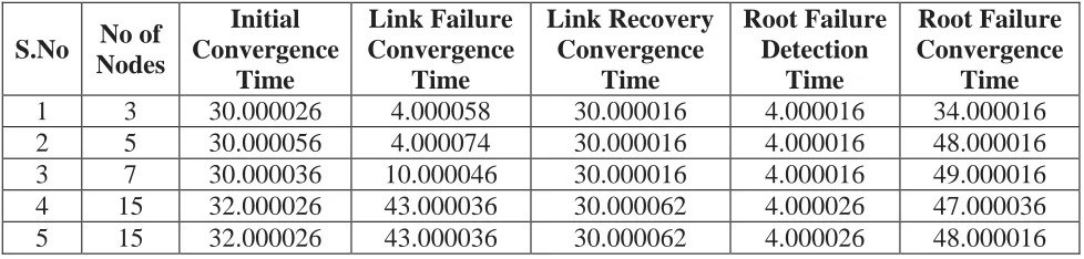
5.1.4.5 Consolidated results
S.No
No of
Nodes
Initial
Convergence
Time
Link Failure
Convergence
Time
Link Recovery
Convergence
Time
Root Failure
Detection
Time
Root Failure
Convergence
Time
1
3
30.000026
4.000058
30.000016
4.000016
34.000016
2
5
30.000056
4.000074
30.000016
4.000016
48.000016
3
7
30.000036
10.000046
30.000016
4.000016
49.000016
4
15
32.000026
43.000036
30.000062
4.000026
47.000036
[image:50.612.62.551.158.275.2]5
15
32.000026
43.000036
30.000062
4.000026
48.000016
TABLE 11: Metrics from all the RSTP topologies
S.No
No of
Nodes
Initial
Convergence
Time
Link Failure
Convergence
Time
Link Recovery
Convergence
Time
Root Failure
Detection
Time
Root Failure
Convergenc
e Time
1
3
0.000046
4.000058
0.000036
4.000016
4.000016
2
5
1.000016
4.000074
0.000052
4.000016
18.000036
3
7
2.000026
10.000046
0.000068
4.000016
19.000032
4
15
3.000032
14.000016
0.000103
4.000026
18.000036
5
15
3.000036
13.000052
0.000103
4.000026
20.000016
TABLE 12: Practical Convergence from all the RSTP topologies
5.1.4.6 Analysis
The above tables summarize the results for all the topologies.
Some observations:
1)
As the number of nodes increase, we can see that all convergence values trend up as well.
50
synchronization process once again, which forces other neighbors to do the same, until the
sync cascades through the topology. This trial and error process causes a delay that
increases significantly in larger topologies.
2)
The values for 7 node and 15 node topologies are in the same range. This is because the 15
node topology is only about 5 nodes “deep”. The depth or radius of a topology is the
number of hops it takes to get from the farthest node to the root node after the topology has
resolved.
3)
We defined all convergence parameters as time taken for all the ports to reach steady state.
With the RSTP synchronization process, once a port reaches alternate/discarding state, the
port opposite to it is not able to complete synchronization. Thus, it cycles through
listening-learning-forwarding. While this process adds to the total time taken for all ports to reach
steady state, the time taken is not reflective of traffic impact (since that link was not going
to be used anyway). Accounting for this behavior, the second table shows practical
convergence values.
5.2 MTP implementation
This section describes the specifics of the MTP model created in OPNET.
5.2.1 Assumptions
51
5.2.2 Frame formats
The following frame formats have been used.
1)
Basic frame
Sender Address (8 bits)
Destination Address(8 bits)
ID (4 bits)
Hops (8 bits)
This frame is the placeholder for data frames sent from one host to another. Simulated hosts on the
network generate this frame, add their own address (Sender address), and select a destination
address (randomly). The ID value is used to track frames to see which ones reached their
destination and which ones were lost. The Hops field is used as an indicator of the path taken, to
gauge whether the frame took the most optimal path to the destination.
2)
VID Advertisement
Mode (8 bits)
Path Cost (8 bits)
Next Child VID (32 bits)
Switch ID (32 bits)
This is the VID advertisement sent by each switch to its neighbors. Mode and Path cost are not
being used at this time. The Next Child VID field contains the VID being offered to the child
switch. Switch ID is the ID of the sender.
At start of simulation, once the root is determined, the root sends out initial VID advertisements.
As a child switch receives a VID advertisement, it populates its VID table and generates
advertisements for its neighbors.
3)
VSAT update
Host Add (32
bits)
VID list (32
bits)
Neighbor flag (1
bit)
Switch ID (32
bits)
Seq No (32
bits)
52
VSAT updates are sent as a result of new information seen in the VSAT table. A data frame whose
Source Address was never seen before causes a new entry in the VSAT table, which in turn causes
a VSAT update to be sent.
When a data frame is sent by a host to its connected switch, the switch records an entry in the
VSAT table for the source address in the data frame. A VSAT update is sent out with Neighbor
Flag set to 1 for this host address. As other switches receive the VSAT update, they check to see
if they have an existing entry for that host address. Sequence number is used to determine if this
is a new update. If the update is new, the VSAT table is updated and the VSAT update s forwarded
after resetting the neighbor flag.
4)
Hello
Type (8 bits)
VID list (32 bits)
Switch ID (32 bits)
Hello Frames have various functions depending on the Type. There are 3 types of Hellos.
Type_null: This is used when a switch joins the network but is not a root. A null hello alerts
neighboring switches about presence of a new switch. Upon receiving a null hello, a switch will
send out a VID Advertisement and VSAT updates to the new switch. The VID list field will contain
a dummy value in a null hello.
Type_periodic: All switches send a periodic hello message to adjacent switches. This indicates
that links are up and the topology did not change.
53
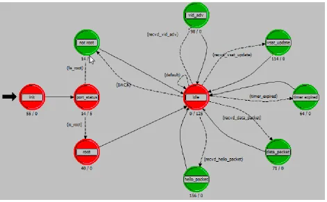
[image:54.612.72.543.133.424.2]5.2.3 State diagram and state definitions
FIGURE 37: State machine for MTP
Init state
This state Initializes all the lists, tables and variables.
Port_status state
54
Root state
We enter this state if the node is Root. The root makes the initial VID advertisement and sends on
all active ports. The root also creates its own VID table.
Not_Root state
We reach this state if the node was not selected to be root. In this state, the node sends out a NULL
hello. This will trigger VID and VSAT updates from nodes that receive it in case a new node joins
the mix. We come back to this state every 2 seconds (by default) as long as a null interrupt is
received- this means it got no VID.
Idle state
This is the resting state for a node when all actions related to an interrupt have been performed.
The following events will trigger further action:
1)
VID advertisement is received
2)
VSAT update is received
3)
Data Packet is received
4)
Hello Packet is received
5)
A timer expires
This state also handles timer based internal events like sending periodic hellos.
VID_adv state
55
VSAT_update state
We enter this state when a VSAT update is received. The update is either accepted and added to
the VSAT table, or discarded as being stale information.
Timer_expired state
This state deals with the timers on the entries of the VID table. If a timer expires, that entry is aged
out and corresponding updates are sent to neighbors.
Data_packet process
This state deals with a received data packet. If the destination address is known ,the packet is
forwarded, else it is dropped. MTP does not flood the network with data packets when the
destination si unknown. This is reasonable because there are no silent nodes these days.
If the source is not known and it is a locally connected host, it is added to the vsat table and vsat
updates are sent.
Hello_packet state
This state deals with all received hello packets. There are 3 types of hello packets- Null Hello,
Periodic Hello and Change Hello.
1.
Null Hello is used to signify a new non-root node in the network. VID advertisements and
VSAT updates are sent to this node.
2.
Periodic Hello is a keep-alive for neighbors. All necessary timers are restarted when this
packet is received.
56
5.2.4 Results
Here we compare RSTP and MTP results for root failure [15]. While root failure in RSTP takes
about 20 sec to resolve (we are considering practical convergence here), in MTP the time to
converge is negligible by comparison. This is because a redundant root is being calculated in the
beginning, so that if the primary root fails, the backup root can take over immediately. Thus we
are able to eliminate the time taken to calculate a new root. RSTP has no such provision for a
redundant root.
The times for root failure in MTP do not include root failure detection time. Thus, we will subtract
[image:57.612.74.543.363.439.2]the detection time from the total root failure convergence time in RSTP for a fair comparison in
TABLE 13:
No. of nodes in Topology
RSTP (sec)
MTP (usec)
5
14
1
7
15
1
15
16
2
TABLE 13: RSTP vs MTP for Root failure[15]
5.2.5 Analysis
57
for second root to take over and b) no links are being blocked so even if the topology flips to the
new root without a true failure, it does not cost any significant network downtime.
6. Conclusion
MTP reduces convergence times in switched networks from the order of seconds to the order of
milliseconds, as demonstrated by the root failure metrics. The down time is so little that no frames
are lost in the process. However, convergence values for MTP only take into account VID
convergence. In order to make a true comparison with RSTP, this value should also include the
convergence time for VSAT tables. Only then can we say that frame forwarding is taking place
correctly. Another approach could be to include information about VIDs generated from backup
root in the original VID table. If this is done, then the new VSAT table can simply be calculated
at each node. This would eliminate any time required for synchronizing the VSAT stables across
the topology.
Since all paths are active, MTP allows networks to make the most of every possible link while
avoiding loops. Since MTP relies on all path and host information being synched across the
network, this will increase computation and storage requirements for switches. Given the
advancements seen in storage and computation, this is not likely to be a real challenge.
7. Directions for further research
58
8. References
[1] David Allan, Peter Ashwood-Smith, et al, “Shortest Path Bridging: Efficient Control of Larger
Ethernet Networks”, IEEE Communications Magazine, October 2010
[2] Radia Perlman, “Rbridges: Transparent Routing ”, IEEE INFOCOM 2004
[3] LAN/MAN Standards committee of the IEEE Computer society,ed. (1998). ANSI/IEEE Std
802.1D, 1998 Edition, Part 3: Media Access Control (MAC) Bridges. IEEE Standard. N. Shenoy,
Y. Pan, D.
[4] Narayan, D. Ross and C. Lutzer, “Route robustness of a multi-meshed tree routing scheme for
Internet MANETs,” Proceeding of IEEE Globecom 2005. 28th Nov to 2
ndDec. 2005 St Louis, pp.
3346-3351.
[5] N. Shenoy and S. Mishra, “Multi-Hop, Multi-Path and Load Balanced Routing in Wireless
Mesh Networks,” Book Chapter in Encyclopedia on Ad Hoc and Ubiquitous Computing,
Published by World Scientific Book Company, 2008.
[6] N. Shenoy, Y. Pan and V.Reddy “Quality of service in Internet MANETs,” Proc. of IEEE 16th
Intl. Symposium on Personal, Indoor & Mobile Radio Communications (PIMRC), 2005, pp.
1823-1829.
[7] N. Shenoy and Y. Pan. “Multi-meshed tree routing for Internet MANETs,” Proc. of 2nd
International Symposium on Wireless Communication Systems, pp. 145-149.
[8] S. Pudlewski, N. Shenoy, Y. Al-Mousa, Y. Pan Y and J. Fischer, “A hybrid multi meshed tree
routing protocol for wireless ad hoc
networks,” Second IEEE International Workshop on Enabling Technologies and Standards for
59
[9] Ethernet Switches, by Joann Zimmerman, Charles E. Spurgeon, Publisher: O'Reilly Media,
Inc. Release Date: April 2013
[10] Touch, J. and R. Perlman, "Transparent Interconnection of Lots of Links (TRILL): Problem
and Applicability Statement," RFC 5556, May 2009.
[11]http://ciscodocuments.blogspot.com/2011/06/chapter-1-network-fundamentals-review_6527.html
[12]
https://www.urz.uni-heidelberg.de/Netzdienste/docext/3com/superstack/3_0/3500/3i3bridg3.html
[13]
http://www.cisco.com/c/en/us/support/docs/lan-switching/spanning-tree-protocol/24062-146.html
[14]http://www.cisco.com/c/en/us/td/docs/switches/datacenter/nexus5000/sw/configuration/guid
e/cli/CLIConfigurationGuide/RPVSpanningTree.html
60
9. Appendix
Transcripts from RSTP output
Transcript from Opnet output for Seed 97 - 3 node topology
_______________ OPNET Simulation Debugger _______________
Type 'help' for Command Summary
ODB> continue
61
State of Port number 2 for BRIDGE 4 being set to FORWARDING at 0.000036 State of Port number 1 for BRIDGE 4 being set to FORWARDING at 0.000046 State of Port number 3 for BRIDGE 3 being set to BLOCKING at 0.000046 State of Port number 2 for BRIDGE 5 being set to LEARNING at 15.000026 State of Port number 2 for BRIDGE 5 being set to FORWARDING at 30.000026 State of Port number 1 for BRIDGE 4 being set to DISABLED at 100.000000 State of Port number 1 for BRIDGE 5 being set to DISABLED at 100.000000 State of Port number 3 for BRIDGE 3 being set to LISTENING at 104.000026 State of Port number 3 for BRIDGE 3 being set to FORWARDING at 104.000058 State of Port number 1 for BRIDGE 4 being set to LISTENING at 200.000000 State of Port number 1 for BRIDGE 5 being set to LISTENING at 200.000000 State of Port number 2 for BRIDGE 5 being set to LISTENING at 200.000016 State of Port number 1 for BRIDGE 5 being set to FORWARDING at 200.000016 State of Port number 3 for BRIDGE 3 being set to BLOCKING at 200.000032 State of Port number 1 for BRIDGE 4 being set to FORWARDING at 200.000036 State of Port number 2 for BRIDGE 5 being set to LEARNING at 215.000016 State of Port number 2 for BRIDGE 5 being set to FORWARDING at 230.000016 State of Port number 2 for BRIDGE 3 being set to LISTENING at 304.000016 State of Port number 3 for BRIDGE 3 being set to FORWARDING at 304.000016 State of Port number 2 for BRIDGE 3 being set to LEARNING at 319.000016 State of Port number 2 for BRIDGE 3 being set to FORWARDING at 334.000016 |---|
| Simulation Completed - Collating Results. |
| Events: Total (3,034,902); Average Speed (491,402 events/sec.) | | Time : Elapsed (6.2 sec.); Simulated (8 min. 20 sec.) | | DES Log: 1 entry |
62
Transcript from Opnet output for Seed 97 - 5 node topology
_______________ OPNET Simulation Debugger _______________
Type 'help' for Command Summary
ODB> continue
63
64
65
State of Port number 1 for BRIDGE 5 being set to FORWARDING at 340.000032 State of Port number 2 for BRIDGE 7 being set to FORWARDING at 348.000016 |---|
| Simulation Completed - Collating Results. |
| Events: Total (4,731,856); Average Speed (471,347 events/sec.) | | Time : Elapsed (10 sec.); Simulated (8 min. 20 sec.) | | DES Log: 1 entry |
|---|
Transcript from Opnet output for Seed 97 - 7 node topology
_______________ OPNET Simulation Debugger _______________
Type 'help' for Command Summary
ODB> continue
66
67
68
69
State of Port number 2 for BRIDGE 9 being set to LISTENING at 316.000032 State of Port number 1 for BRIDGE 9 being set to FORWARDING at 316.000032 State of Port number 3 for BRIDGE 3 being set to FORWARDING at 316.000042 State of Port number 1 for BRIDGE 9 being set to LISTENING at 316.000042 State of Port number 2 for BRIDGE 9 being set to FORWARDING at 316.000042 State of Port number 1 for BRIDGE 7 being set to LISTENING at 316.000052 State of Port number 3 for BRIDGE 7 being set to LISTENING at 316.000052 State of Port number 2 for BRIDGE 8 being set to LISTENING at 316.000052 State of Port number 2 for BRIDGE 9 being set to LISTENING at 316.000052 State of Port number 1 for BRIDGE 9 being set to FORWARDING at 316.000052 State of Port number 1 for BRIDGE 9 being set to BLOCKING at 316.000062 State of Port number 2 for BRIDGE 9 being set to FORWARDING at 316.000062 State of Port number 3 for BRIDGE 6 being set to FORWARDING at 316.000068 State of Port number 2 for BRIDGE 6 being set to FORWARDING at 316.000078 State of Port number 1 for BRIDGE 9 being set to LISTENING at 317.000016 State of Port number 1 for BRIDGE 9 being set to BLOCKING at 317.000026 State of Port number 3 for BRIDGE 7 being set to FORWARDING at 318.000016 State of Port number 2 for BRIDGE 7 being set to LISTENING at 318.000026 State of Port number 1 for BRIDGE 7 being set to FORWARDING at 318.000026 State of Port number 1 for BRIDGE 9 being set to LISTENING at 319.000016 State of Port number 1 for BRIDGE 3 being set to LEARNING at 319.000016 State of Port number 2 for BRIDGE 6 being set to BLOCKING at 319.000016 State of Port number 2 for BRIDGE 8 being set to BLOCKING at 319.000032 State of Port number 1 for BRIDGE 5 being set to LEARNING at 325.000032 State of Port number 2 for BRIDGE 7 being set to LEARNING at 333.000026 State of Port number 1 for BRIDGE 9 being set to LEARNING at 334.000016 State of Port number 1 for BRIDGE 3 being set to FORWARDING at 334.000016 State of Port number 1 for BRIDGE 5 being set to FORWARDING at 340.000032 State of Port number 2 for BRIDGE 7 being set to FORWARDING at 348.000026 State of Port number 1 for BRIDGE 9 being set to FORWARDING at 349.000016 |---|
| Simulation Completed - Collating Results. |
70
| DES Log: 1 entry | |---|
Transcript from Opnet output for Seed 97 - 15 node topology scenario 1
_______________ OPNET Simulation Debugger _______________
Type 'help' for Command Summary
ODB> continue
71
72
73
74
75
76
77
78
79
80
81
State of Port number 2 for BRIDGE 10 being set to LEARNING at 319.000026 State of Port number 1 for BRIDGE 5 being set to LEARNING at 325.000062 State of Port number 2 for BRIDGE 6 being set to LEARNING at 331.000016 State of Port number 3 for BRIDGE 12 being set to LEARNING at 331.000026 State of Port number 2 for BRIDGE 15 being set to LEARNING at 331.000032 State of Port number 2 for BRIDGE 8 being set to LEARNING at 331.000042 State of Port number 3 for BRIDGE 16 being set to LEARNING at 332.000036 State of Port number 1 for BRIDGE 3 being set to FORWARDING at 334.000026 State of Port number 2 for BRIDGE 10 being set to FORWARDING at 334.000026 State of Port number 1 for BRIDGE 5 being set to FORWARDING at 340.000062 State of Port number 2 for BRIDGE 6 being set to FORWARDING at 346.000016 State of Port number 3 for BRIDGE 12 being set to FORWARDING at 346.000026 State of Port number 2 for BRIDGE 15 being set to FORWARDING at 346.000032 State of Port number 2 for BRIDGE 8 being set to FORWARDING at 346.000042 State of Port number 3 for BRIDGE 16 being set to FORWARDING at 347.0000
![FIGURE 3: STP port states [9]](https://thumb-us.123doks.com/thumbv2/123dok_us/40092.3258/11.612.111.494.418.636/figure-stp-port-states.webp)
![FIGURE 4: Port Transition Sequence [11]](https://thumb-us.123doks.com/thumbv2/123dok_us/40092.3258/12.612.154.460.107.239/figure-port-transition-sequence.webp)