Int. J. Electrochem. Sci., 13 (2018) 4891 – 4900, doi: 10.20964/2018.05.33
International Journal of
ELECTROCHEMICAL
SCIENCE
www.electrochemsci.orgMini Review
Material Corrosion in Molten Fluoride Salts
Yanli Wang1, Shenghua Zhang2,*, Xiaohong Ji1, Ping Wang1, Weihua Li1,3
1
School of Chemistry and Chemical Engineering, Guangxi University, Nanning, 530004, P R China.
2
School of Resources, Environment and Materials, Guangxi University, Nanning, 530004, P R China.
3
School of Chemical Engineering and Technology, Sun Yat-sen University.
*
E-mail: wyl15104008565@126.com
Received: 25 January 2018 / Accepted: 7 March 2018 / Published: 10 April 2018
Molten Salt Reactors (MSRs) have received worldwide attention due to its favorable economics, fueled utilization and safety characteristics. The fuel and coolant of MSRs are both molten fluoride salts. The subsequent molten salt induced structural material corrosion problem is a bottleneck during the development of MSRs, and thus has been investigated extensively. In this paper, the influence factors and mechanisms of material corrosion in molten fluoride salts are fully discussed.
Keywords: Molten fluoride salts, Mechanism, Corrosion, Molten salt reactors.
1. INTRODUCTION
Molten salt reactors (MSRs) are the priority in the development of the fourth generation reactors, due to their favorable economics, fuel utilization and safety characteristics [1]. Molten salts appear to be excellent candidates as heat transfer media in nuclear reactors due to their thermophysical and thermochemical properties. The standards for candidate molten salts as heat transfer coolants have been developed by ORNL (Oak Ridge National Laboratory-USA) researchers [2]: (1) High chemical stability at temperature ranges from 500 to 800 oC; (2) High radiolytic stability, especially for the primary coolant; (3) Low melting point, preferably lower than 525 oC; (4) Large specific heat and thermal conductivity; (5) Low vapor pressures at operating temperature and non-volatile; (6) Good compatibility with high- temperature structural materials.
salts, and BeF2-containing salts (e.g. LiF-BeF2) [5]. Because beryllium is extremely toxic and
environmentally harmful, an environmentally friendly eutectic LiF-NaF-KF molten salt is widely used as simulator fluid and experimental salt [6, 7].
However, the corrosion of structural materials caused by molten fluoride salts is an inevitable problem for the application and development of MSRs. Over the past 60 years, a lot of efforts have been dedicated to the issues of molten fluoride salts induced corrosion. Many research institutions, such as ORNL (Oak Ridge National Laboratory-USA), the University of Wisconsin, and National Institute for Fusion Science (NIFS), have conducted many experiments on the corrosion behavior of materials in various molten salts [2, 4, 5, 8, 9]. The higher the Cr content in the materials is, the larger the weight loss of structural alloys show. Thus, nickel alloys with a low chromium content is considered to be the most appropriate materials for MSRs. Among these alloys, Hastelloy-N (Ni-17%Mo-7%Cr-5%Fe, mass percent), which was developed by ORNL shows great potential for long-term applications. Koger repoeted that Hastelloy-N exhibited a corrosion rate of less than 0.0025mm/year at 704 oC in the LiF-BeF2 fuel salt and approximately 0.015mm/year at 607 oC in the
NaBF4-NaF coolant salt [3]. The purpose of this paper is to determine the main causes of material corrosion in molten fluorides and explain the corrosion mechanisms.
2. MAIN CAUSES OF MATERIAL CORROSION IN MOLTEN FLUORIDE SALTS
An immediate challenge for using molten fluoride salts during the development of nuclear reactors is their corrosive nature at the desired operating temperature range between 650 and 850 °C. In most traditional high temperature processes, materials mainly obtain the corrosion resistance by forming a dense protective oxide film such as Cr2O3, Al2O3 or SiO2 on the surface. In molten fluorides,
however, these metal oxides are dissolvable. Corrosion in molten fluorides mainly occurs through the dissolution of alloying elements into the melt [10-12]. The key driving force for the corrosion is the difference in the free energy between the salt constituents and the corresponding fluorides of the alloy compositions. The free energy of salt constituents such as LiF, NaF, and KF, is more negative than those of the fluorides for any constituents of alloys, thus corrosion of alloys can hardly occur in pure molten fluoride salts. However, in actual system, several kinds of corrosion reactions may occur. The main driving forces for the corrosion in molten fluorides generally involve impurities in the fluorides, temperature gradients and galvanic corrosion.
2.1 Effect of impurities in fluoride salts
Corrosion by oxidant impurities, such as H2O, HF, residual metal oxides of metals, and easily
The higher content of impurities is, the more aggressive the melts are. In actual service environment of molten (Li,Na,K)F with extremely low level of moisture, the corrosion induced by dissolved water will cease or self-limiting when the moisture has been consumed or the solubility limits of the transition metal fluorides in molten fluoride salt are reached, unless the water vapor is continuously replenished by infiltrating into the experimental system [2, 6, 14].
Early works with Hastelloy-N and other alloys, revealed the corrosion behaviors that were caused by impurities in molten fluoride salts [2, 6, 9, 15-18]. Ouyang investigated the corrosion behavior of Ni-based alloys in molten alkali fluoride (Li,Na,K)F with moisture. He observed that higher moisture content aggravated intergranular corrosion and pitting [17]. Kondo also reported that the corrosion of JLF-1 in purified (Li,Na,K)F was much less than that in (Li,Na,K)F with a certain content of impurities [9]. Koger investigated the effect of the FeF2 additions on corrosion in a
Hastelloy-N-LiF-BeF2-UF4 system. The experimental results showed that, the maximum weight loss
rate before the FeF2 additions was 1×10⁻⁴ mg·cm-2·hr-1, which is an order of magnitude smaller than
that after the FeF2 additions [19]. Xue [20] and Wang [21, 22] reported the effects of Cr3+ on the
corrosion of pure metals Ni, Fe, and Cr, and GH3535 alloy and SiC. They found that the Cr3+ can increase the corrosion of Fe, Cr, and GH3535 alloy and SiC, but has no effect on the corrosion of Ni. Therefore, the removal of water and the impurity contents in molten fluoride salt, and maintaining them at an acceptable level are other goals of the current research. At present, there are several physical and chemical methods for the purification of the salts before their use: (1) vacuum drying fluoride salts under 10-3mm Hg pressure and high temperature [23]; (2) sparging the molten fluorides with HF/H2 [4, 5, 7, 24]; (3) add 15wt% NH4HF2 to the molten fluoride salts [23]; (4) melting salt
electrolysis process [9].
2.2 Effect of temperature gradient
Different diffusion coefficients and solubilities due to thermal gradients in molten fluoride salts are the main causes of sustained corrosion in MSRs. The main corrosion reaction in molten fluoride salts is the selective removal of chromium [6, 11, 12, 25, 26],
Cr + Oxidant→Reductant + CrF2. (1)
However, these equilibrium constants of the corrosion reactions in molten fluoride salts, such as
Cr + 2UF4→2UF3 + CrF2, (2)
molten salts. In some melt, such as NaF-KF-LiF-UF4, the equilibrium constant changes sufficiently as
a function of the temperature to cause dendritic chromium crystals to form in the cold zone. However, for the LiF-BeF2-UF4 mixtures, the temperature dependence of the mass transfer reaction is small [28,
29]. If the temperature gradient is sufficient to build a convection cell in molten fluoride salts and maintain unsaturated conditions in the hot section, the dissolution and deposition reactions can be a sustained, persistent corrosion process [2, 6]. Furthermore, severe fouling and plugging phenomena will appear with this process in a circulating system.
In a Hastelloy-N-LiF-BeF2-UF4 thermal convection loop system (maximum temperature 704 o
C, minimum temperature 538 oC), Koger observed the mass transfer from the hot leg to the cold leg. Furthermore, no voids were observed in the hottest specimens, as the surface layer was completely removed by the corrosion process [19]. Williams also found the weight increase in hot area and weight loss in cold area due to the dissolution of chromium in hot parts and the formation of CrF2 in colder
sections [27]. Wang investigated the corrosion behavior of Ni, Mo, Fe, Cr, GH3535 and 316L stainless steel in molten (Li,Na,K)F with temperature gradients, founding that the difference in the temperature of the melt could cause the difference of the corrosion potential, and thus probably lead to the occurrence of galvanic corrosion [30].
2.3 Effect of galvanic corrosion
Galvanic corrosion is one of the electrochemical corrosion mechanisms in the molten fluorides. The galvanic corrosion is mainly caused by the potential difference between metals or alloys in molten fluoride salts which maintained them in electrical contact [2, 6, 13]. It can occur not only as a macroscopic process when two metals or alloys with different electromotive potentials are in electrical contact in molten salts. It can also occur as a microscopic process between the alloy matrix and the precipitates [8, 31].
Kondo studied the corrosion behavior of JLF-1 (8.92Cr-2W) in molten LiF-BeF2 and
(Li,Na,K)F salts, it is observed that the corrosion rate of the steel in nickel crucible is much larger than that in JLF-1 crucible [26]. Olson also observed that the corrosion rate in molten fluorides for Incoloy 800H was much greater in a graphite crucible compared to an Incoloy 800H crucible [8]. Ye reported that a concentration-gradient for Cr and Mo between the M12C carbide and the Hastelloy N could
induce the severe corrosion of M12C carbides [18]. Wang investigated the weld corrosion of GH3535
alloy in at 700 oC in molten (Li,Na,K)F, finding that when the weld zone of the GH3535 is coupled with the parent alloy, galvanic corrosion occurs and the galvanic corrosion effect is larger than 1 [30]. Wang also found that when the metal Ni is coupled with Fe and Cr, galvanic corrosion occurs due to the large potential differences [32].
3. MATERIAL CORROSION MECHANISMS IN MOLTEN FLUORIDE SALTS
electrochemical changes. In general, the material corrosion mechanisms in molten fluoride salts are quite similar to those in aqueous solutions. The main corrosion mechanisms in aqueous systems, such as uniform surface corrosion, pitting corrosion, intergranular corrosion and galvanic corrosion, are also common in molten fluoride salts. However, the mechanisms of corrosion attack by molten fluoride salts in MSRs have never been fully understood by researchers in this field. In this paper, it is generally agreed that most corrosion mechanisms in molten fluoride salts involve with electrochemical corrosion.
3.1 The potential-acidity diagrams and the stability diagrams
Based on the Nernst Quation and the thermodynamic data from HSC 6.0, potential-oxoacidity diagrams in molten LiF-NaF-KF (a(LiF)=0.465) system at 700 oC for the main elements of the structural materials, Ni, Fe, Cr, Mo, are calculated, as shown in Fig.1. The calculate principal is similar with the potential-acidity diagrams in FLiBe fluoride salt reported by Delpech [25]. These diagrams show the stability domains of elements under their different forms as a function of potential and oxoacidity (which is related to the oxide concentration in the salt) in a fluoride environment.
Despite the large thermodynamical stability of the fluoride salts in comparison to the main constituents of the structural materials, the fluoride salts are still extremely corrosive environments due to the potential existence of free fluorine, which will readily attack the structural materials. This phenomenon becomes especially severe when impurities are present in the melt [34]. The fluorine potential of the melt is defined as follows[24, 33]:
ΔGF2 = RT ln PF2 . (3)
And Lanrenty [35] gave the equation of the metal fluoride content [MF] in the salt: [MF]in salt= 1/γ[MF] *Kr *a[M in alloy]* PF20.5 . (4)
Therefore, to mitigate the fluorine driven corrosion, we can control the fluorine potential by minimizing the pressure of F2. Olander also presented three ways of controlling the fluorine potential
of FLiBe: by the gas mixture H2/HF; by one of the major metals of FLiBe (Be or Li); or by a donor salt
such as CeF3/CeF4 [24].
Figure 1. Potential-acidity diagrams calculated at 700 °C for Ni (a), Mo (b) Fe (c), and Cr (d), in LiF-NaF-KF fluoride salt (a(LiF) = 0.465) [21].
[image:6.596.117.481.67.393.2] [image:6.596.105.492.464.747.2]
The influence of impurity H2O on alloy corrosion behavior in molten fluoride salt systems can
be understood through the potential-acidity diagrams and the stability diagrams. The impurity H2O will
react with molten fluoride salt through the following reactions: H2O (g) + 2MF = M2O + 2HF (g), (5)
2y HF (g) + x Me = MexFy + 2yH2 (g), (6)
M = Li, Na, K, Me = Cr, Fe, Ni.
A high HF pressure results in the increase of the potential and oxoacidity. Thus the constituents of the alloy will easily be oxidized to the metallic fluorides, causing alloy corrosion.
3.2 Intergranular corrosion
Recent reports have shown that alloys in molten fluoride salts always show intergranular corrosion [6, 11, 17, 34, 35]. Furthermore, the deepest penetration and first sign of attack always occur in the grain boundaries.
Figure 3. Electrochemical process of intergranular corrosion in molten fluoride salt.
[image:7.596.231.376.334.490.2] [image:7.596.198.397.544.716.2]
Actually, it is the result of the difference in potential between anodic grain boundaries and the cathode grains. Fig. 3 shows the electrochemical process of intergranular corrosion in molten fluoride salt. The main electrochemical reactions are as the following:
Anodic reaction: Cr = Cr2+ + 2e (7) Cathodic reaction: H+ + e = 1/2 H2 (g) (8)
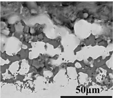
Wang [35] performed corrosion tests of Fe based austenite alloys in molten LiF-NaF-KF salt. A corrosion effect was particularly pronounced at the grain boundaries, as shown in Fig. 4. You et al. also found intergranular corrosion of Haynes 242 in molten FLiNaK salt after 600 h experiment [6].
3.3 Temperature gradient corrosion
Metals or alloys will experience dissolution (hot leg)-deposition (cold leg) reactions due to the existence of temperature gradient in MSR. The exchange current density for the fluoridation process in molten fluorides increased with the temperature [36]. Furthermore, these reactions are self-sustaining, causing material failure while on service. In actual, these reactions are electrochemical processes. Fig.5 shows the electrochemical processes of temperature gradient corrosion in MSR. The chromium of alloy is selectively dissolved by the fluorides and the chromium at the surface of the alloy is replaced through a diffusion process, forming the holes in the hot leg specimen. W. D. Manly proposed a mechanism to explain the formation of the holes [37]. The cathodic deposition of chromium, as shown in the cold leg specimen, is so serious that it causes the fuel loop plugging. Wang [26] proposed that the temperature gradient corrosion is basically galvanic corrosion. The hot region samples serve as the anode of the couples and the cold region samples serve as the cathode. The metal ions produced by the dissolution of the hot region samples could diffuse toward the cold region samples, and then be reduced, resulting in the continued dissolution of the hot region samples.
4. CONCLUSIONS
Temperature gradient, galvanic corrosion and impurities in molten fluoride salt systems are the three main reasons for structural material corrosion. The potential -acidity diagrams and stability diagrams of the Ni-F-O, Mo-F-O, Fe-F-O, and Cr-F-O systems are given to help to understand the main corrosion reactions of the structural materials, and also further understand the corrosion mechanisms. The impurities H2O, HF, FeF2, and the oxides of metals and fission products from salts
ACKNOWLEDGEMENTS
This project is supported by the Bagui Scholars Program of Guangxi Autonomous Region in 2016, the Academician Workstation Building Project of Guangxi Zhuang Autonomous Region Scientific and Technological Department [Grant No. [2014] 91].
References
1. M.W. Rosenthal, P.R. Kasten, R.B. Briggs, ORNL, (1969). 2. M. Sohal, M. Ebner, P. Sabharwall, P. Sharpe, INL., (2010). 3. J.W. Koger, Corrosion, 29 (1973) 115.
4. D.F. Williams, ORNL/TM-2006/69, (2006).
5. D. Williams, L. Toth, K. Clarno, ORNL/TM-2006/12, (2006). 6. Y. Bojian, NTHU., (2010).
7. L.C. Olson, UWM., (2009).
8. L.C. Olson, J.W. Ambrosek, K. Sridharan, M.H. Anderson, T.R. Allen, J. Fluorine Chem., 130 (2009) 67.
9. M. Kondo, T. Nagasaka, V. Tsisar, A. Sagara, T. Muroga, T. Watanabe, T. Oshima, Y. Yokoyama, H. Miyamoto, E. Nakamura, N. Fujii, Fus. Eng. Des., 85 (2010) 1430.
10.W.R. Grimes, ORNL/TM-1853, (1967).
11.L. Olson, K. Sridharan, M. Anderson, T. Allen, Mater. High Temp., 27 (2010) 145.
12.M. Liu, J.Y. Zheng, Y.L. Lu, Z.J. Li, Y. Zou, X.H. Yu, X.T. Zhou, J. Nucl. Mater., 440 (2013) 124. 13.P. Sabharwall, M. Ebner, P. Sharpe, M. Anderson, Molten salts for high temperature reactors,
ORNL, (2010).
14.J.R. Keiser, ORNL/TM-5783, (1977).
15.M.W. Rosenthal, P.N. Haubenreich, R.B. Briggs, ORNL-4812, (1972). 16.A.L. Mathews, C.F. Baes, ORNL-TM-1129, (1965).
17.F.Y. Ouyang, C.H. Chang, B.C. You, T.K. Yeh, J.J. Kai, J. Nucl. Mater., 437 (2013) 201. 18.X.X Ye, H. Aia, Z. Guo, H. Huang, L. Jiang, J. Wang, Z. Lia, X. Zhou, Corros. Sci., 106 (2016)
249.
19.J.W. Koger, ORNL/TM-4188, (1972).
20.W. Xue, X. Yang, J. Qiu, H. Liu, B. Zhao, H. Xia, X. Zhou, P. Huai, H. Liu, J. Wang, Corros. Sci., 114 (2017) 96.
21.Y.L. Wang, Q. Wang, H.J. Liu, C.L. Zeng, Corros. Sci., 103 (2016) 268. 22.Y. Wang, H. Liu, G. Yu, J. Hou, C. Zeng, J. Fluorine Chem., 178 (2015) 14. 23.S.H. White, Plenum Press, 1(1983) 1.
24.D. Olander, J. Nucl. Mater., (2002) 270.
25.S. Delpech, C. Cabet, C. Slim, G.S. Picard, Mater. Today. 13(2010) 34.
26.M. Kondo, T. Nagasaka, Q. Xu, T. Muroga, A. Sagara, N. Noda, D. Ninomiya, M. Nagura, A. Suzuki, T. Terai, N. Fujii, Fusion Engineering and Design. 84 (2009) 1081.
27.D.F. Williams, D.F. Wilson, L.M. Toth, J. Caja, J.R. Keiser, Research on molten fluorides as high temperature heat transfer agents, In Globle 2003, Session 2A: Coolant/Material Interactions in Advanced Reactor Systems,Embedded Topical Within 2003 American Nuclear Society Winter Meeting, (2003) 1-12.
28.J.W. Koger, ORNL, 30 (1973) 1.
29.W.R.Grimes, Nucl. Appli. Tech., 8 (1970) 137. 30.Y. Wang, UCAS., (2016).
34.F.Y. Ouyang, C.H. Chang, J.J. Kai, J. Nucl. Mater., 446(2014)81.
35.Yanli Wang, Huijun Liu, Chaoliu Zeng, Weihua Li, Int. J. Electrochem. Sci., 13 (2018) 1629. 36.W. Wu, S. Guo, J. Zhang, J. Eectrochem. Soc., 164 (2017) C840.
37.G.M. Adamson, R.S. Crouse, W.D. Manly, ORNL-2237, (1959) 1.
![Figure 1. Potential-acidity diagrams calculated at 700 °C for Ni (a), Mo (b) Fe (c), and Cr (d), in LiF-NaF-KF fluoride salt (a(LiF) = 0.465) [21]](https://thumb-us.123doks.com/thumbv2/123dok_us/1787551.133025/6.596.105.492.464.747/figure-potential-acidity-diagrams-calculated-fluoride-salt-lif.webp)