Article ID: G23281
Geometry and slip rate of the Aigion Fault, a young normal
1fault system in the western Gulf of Corinth
2L.C. McNeill 3
C.J. Cotterill* 4
J.M. Bull 5
T.J. Henstock 6
R. Bell 7
National Oceanography Centre, School of Ocean and Earth Science, University of
8
Southampton, Southampton SO14 3ZH, UK
9
A. Stefatos 10
Laboratory of Marine Geology and Physical Oceanography, University of Patras, Patras
11
26500, Greece
12
*Current address: British Geological Survey, West Mains Road, Edinburgh, EH9 3LA 13
ABSTRACT 14
The Aigion fault is one of the youngest major normal faults in the Gulf of Corinth, 15
Greece, with an immature displacement profile. Based on geometry, slip rate and comparison 16
with regional faults, we estimate the fault system length at ~10 km. We find the slip rate of 17
the fault system is ~3.5 ± 1 mm/yr decreasing to ~2.5 ± 0.7 mm/yr close to its eastern tip. 18
Complex fault geometry and displacement profiles on the shelf east of Aigion are consistent 19
with the latter as the eastern tip location. Analysis of slip on this fault system and the 20
established fault to the south (Western Eliki Fault) suggests that slip was transferred rapidly 21
but not homogeneously between the two faults during the period of contemporaneous activity. 22
Together with a lack of evidence of lateral propagation at the eastern fault tip in the last 10– 23
Article ID: G23281
its 200–300 k.y. history. These results contribute to our understanding of the process of 25
northward fault migration into the rift and the development of new normal faults. 26
Keywords: Corinth rift, normal faults, continental rifting, fault development 27
INTRODUCTION 28
The Gulf of Corinth is renowned for high extension rates, seismicity and dramatic rift 29
morphology. Our understanding of the rift geometry has evolved over the last decade from a 30
simple half-graben model to a more complex model of varying geometry in space and time, 31
with multiple major faults accommodating strain across the rift and hangingwall migration of 32
rift-bounding faults (e.g., Armijo et al., 1996; Moretti et al., 2003; Stefatos et al., 2002; 33
DeMartini et al., 2004; McNeill et al., 2005). 34
The Aigion fault system (AF, Fig. 1) in the western Gulf is unusual for two reasons: it 35
is contemporaneously active with part of an overlapping fault system (Western Eliki) and has 36
a non-constant (and limited) displacement profile with decreasing displacement from west to 37
east. It has therefore been interpreted as an immature fault (e.g., DeMartini et al., 2004; 38
Micarelli et al., 2003), probably propagating to the east and possibly part of the northward 39
fault migration in the rift. No historic earthquakes are confirmed on the Aigion fault but 40
paleoseismological studies confirm Holocene activity (Pantosti et al., 2004) potentially 41
supported by microseismicity (e.g., Rigo et al., 1996). Cracks, coastal slumping and 42
liquefaction in the Aigion area resulted from an offshore-generated earthquake in 1995. 43
We collected high resolution seismic and multibeam bathymetric data in the western 44
Gulf of Corinth in July, 2003 (McNeill et al., 2005; Cotterill, 2006 for further details). A grid 45
of 25–100 m spaced multichannel boomer seismic lines were collected over the shelf east of 46
Aigion (Fig. 1). Using these high resolution data, this paper reveals the geometry of the 47
eastern extension and tip of the Aigion fault system (Offshore Aigion Fault, OAF), and 48
Article ID: G23281
whole. We will analyze the Aigion fault age and evidence for rate of fault development and 50
lateral growth to contribute to ongoing debate. This study will also provide insight into the 51
development of new fault systems in this and other continental rifts. 52
53
Seismic Stratigraphy 54
High resolution seismic data resolve sub-horizontal topsets and dipping foresets of the 55
fan delta which are interpreted to represent ~0-80 ka since the last highstand (Fig. 2) based on 56
comparisons with similar studies (e.g., Leeder et al., 2005). Within these deposits, a clear 57
unconformity (H1) is interpreted as the erosional surface formed following transgressional 58
flooding of the basin sill. The Gulf of Corinth deviates from eustatic sea-level fluctuations 59
due to a sill at its western entrance, currently at ~60–65 m depth (Perissoratis et al., 2000), 60
with a lowstand lake level thought to be close to this depth. Away from major active faults, 61
the shelf edge (a lowstand feature) is close to current sill depth, supporting the assumption 62
that the sill has not changed depth significantly in the recent past. A consistent age range for 63
H1 can be estimated from the depth of the basin sill, paleo-shelf elevation range, eustatic sea 64
level curves and dated samples. The seaward-dipping transgressive surface rises from the 65
shelf edge to a minimum of ~40–50 m close to the current coastline (allowing for the effects 66
of Holocene fault displacement). Radiocarbon dates from cores within and outside the study 67
area produce ages just above the horizon of ~9.5–12 ka BP (Perissoratis et al., 2000; Collier et 68
al., 2000; Lemeille et al., 2004). Combining these data with eustatic sea level curves (e.g., 69
Siddall et al., 2003) we estimate sill flooding at ~11–13 ka and flooding of the Aigion paleo-70
shelf and hence the unconformity (H1) age at ~10–13 ka. 71
Geometry of the Aigion and Offshore Aigion Fault Systems 72
The E-W trending Aigion fault system consists of multiple onshore segments (AF) 73
Article ID: G23281
1996; Koukouvelas, 1998; Palyvos et al., 2005; Soter and Katsonopoulou, 1998). Footwall 75
topography and presumably total fault displacement on the main fault segment (AF) at Aigion 76
town gradually decreases from west to east. The main fault probably terminates at or just west 77
of the Meganitis river, but other authors continue the fault further west (Koukouvelas, 1998). 78
West of the Meganitis river and towards the Phoenix River, Palyvos et al. (2005) interpret a 79
series of NW-SE and E-W fault segments (Fassouleika and Selinitika, Fig. 1) along the range 80
front and incorporate these into a larger complex Aigion-Neos-Erineos fault system 81
(ANEFS). East of Aigion town, several authors have proposed an additional segment 82
underlying the Selinous delta (Koukouvelas, 1998; Pantosti et al., 2004), but surface 83
expression is minimal. 84
New seismic data confirm the activity of the eastern offshore part of this fault system 85
and reveal its complex surface and sub-surface geometry (Fig. 3; Cotterill, 2006). The fault 86
system (OAF, Fig. 1) consists of two main faults (1 and 2, Figures 2, 3) forming a graben, and 87
a number of minor faults within the graben and footwalls (Fig. 3). Pockmarks are common 88
and in places are distributed linearly indicating sub-surface blind faults. Three main segments 89
of fault 1, west (A), central (B) and east (C), coincide with left steps in the fault geometry. A 90
change in polarity of the northern fault (2), from S- to N-dipping, is coincident with a 91
significant left step of the southern fault (1) and associated transfer zone with complex 92
faulting between segments B and C. East of this location towards the shelf edge, the graben 93
narrows and there is a significant drop in net displacement (Fig. 3). Other seismic profiles 94
from this study indicate further displacement east of the shelf fault system, suggesting that the 95
fault system damage zone continues a further ~1 km east of the shelf edge. Coastal field 96
investigations along strike from the offshore OAF trace reveal small recent scarps down to the 97
north (Fig. 3). These may be equivalent to the cumulative scarps identified by Pantosti et al. 98
Article ID: G23281
least ~3 km from the coast to just east of the shelf edge (Fig. 3). The N and S-dipping fault 100
splays must converge at a depth of >0.5 km, assuming fault dips of 50–60°. 101
Aigion Area Faulting 102
North of the OAF, the E-W trending Cape Gyftisa fault (CGF, Fig. 1) displaces the 103
seafloor and controls the shelf edge; the displacement and seafloor offset decreases westward 104
toward Cape Gyftisa. Offset of the transgressive surface on several seismic profiles indicates 105
a Holocene slip rate of 1.7 ± 0.5 mm/yr for the CGF. The minor fault in Aigion harbour (Fig. 106
1) is probably not active during the Holocene (from lack of deformation of youngest 107
sediments) and is not clearly connected to the CGF. Figure 1 shows other significant offshore 108
faults (this study; McNeill et al., 2005) with slip rates where estimated. No further major 109
Holocene-active faults are recognized in the Aigion harbour area from our data, although 110
mass wasting and 3D sedimentary-topographic architecture complicate the seismic 111
interpretation. 112
Offshore Aigion Fault Slip Rate 113
Spatially averaged displacement of the transgressive horizon across fault 1 (Figs. 2 114
and 3) is 13 ± 3 m with a maximum of 22 m, and a total spatially averaged displacement 115
across the entire system (all major and significant minor faults) of 27 ± 4 m and maximum of 116
35 m (1σ error, Figure 3; Cotterill, 2006). These displacements decrease close to the shelf
117
edge at the eastern tip of the system at segment C (this segment was not included in 118
displacement calculations). Using 10–13 ka for the transgressive horizon age, averaged 119
Holocene displacement rates are ~1.2 ± 0.4 mm/yr for fault 1 and ~2.5 ± 0.7 mm/yr for the 120
whole OAF fault system. No Holocene lateral fault propagation is measurable from our 121
profile spacing. 122
DISCUSSION 123
Article ID: G23281
Slip rates from several techniques and time periods for regional faults are summarized 125
in Figure 1. To assess slip rates on the Aigion fault (AF), we could simply use the late 126
Pleistocene footwall uplift rate of 1–1.2 mm/yr (DeMartini et al., 2004). Locally and globally 127
derived uplift:subsidence ratios of ~1:2-3 (McNeill and Collier, 2004) then yield a slip rate of 128
~4–7 mm/yr. Dislocation modeling produces a maximum slip rate of 9-11 mm/yr (DeMartini 129
et al., 2004). Alternatively, we can combine subsidence rates from lowstand deltaic 130
clinoforms and shorelines 1–2 km due north of the Aigion fault and Aigion town (McNeill et 131
al., 2005) with footwall terrace uplift rates; both locations are close to the western fault tip 132
where displacements appear highest. Two end-lowstand shorelines are present at ~80–85 m 133
and ~165 m depth. The latter appears to have subsided post-deposition due to slope failure or 134
local faulting, but careful seismic interpretation suggests that the younger clinoform unit is in 135
situ locally. Assuming an age of 11–13 ka, the youngest shoreline produces a subsidence rate 136
of ~1.3–2.5 mm/yr (adjusted for distance from the Aigion fault, e.g., Armijo et al., 1996). The 137
depth of the youngest shoreline contrasts with interpreted end lowstand coastal deposits at 138
~68 m in the AIG-10 borehole (Lemeille et al., 2004) which produce maximum subsidence 139
rates of 0.7 mm/yr; the comparison is probably complicated by multiple fault splays of the 140
Aigion system close to the borehole site. Combining the late Quaternary rates of uplift (1–1.2 141
mm/yr) with Holocene subsidence (~1–2.5 mm/yr) and a fault dip of 60° we calculate slip 142
rates of ~2.5–4.5 mm/yr. We note that this slip rate may combine multiple fault splays and 143
that it combines Holocene subsidence with late Quaternary uplift, therefore representing an 144
averaged rate over this time period. This is in good agreement with maximum late Holocene 145
paleoseismological rates for this fault (Pantosti et al., 2004) and a little lower than late 146
Quaternary rates from applying an uplift:subsidence ratio for this and other Corinth faults (4– 147
7 mm/yr). 148
Article ID: G23281
The age of the Aigion fault system can be estimated from the maximum age of 150
uplifted marine terraces or by combining total offset with slip rate. Previous studies have 151
produced conflicting estimates of the age of the AF ranging from 300 to 25 ka. Naville et al. 152
(2004) and Cornet et al. (2004) used seismic refraction data and vertical seismic profiles 153
around the AIG-10 borehole (0.5 km north of Aigion town and the AF) to suggest total 154
basement offset of only ~150 m. Applying a post-~35 ka slip rate of 3.5 mm/yr to uplifted and 155
subsided dated deposits (Lemeille et al., 2002; 2004) to this offset yields a young fault age of 156
~50 ka (Cornet et al., 2004). A similar age of 25–70 ka (Micarelli et al., 2003) was suggested 157
by interpreting the Aigion town topographic scarp height (150 m) as total offset and applying 158
a similar slip rate of 2-5 mm/yr. However, we support the older age estimate (200–300 ka) 159
from the correlated and partially dated uplifted footwall terraces of DeMartini et al. (2004), 160
based on the following arguments. The Aigion fault footwall uplift from the elevation of 161
marine terraces (~230 m, DeMartini et al., 2004) alone equals or exceeds the borehole fault 162
displacement requiring no hangingwall subsidence for consistency. The number and elevation 163
of mapped footwall terraces are inconsistent with an age of ~50 ka and yield good correlation 164
with Oxygen Isotope Stage 5 and 7 highstands. In addition, we question the use of 165
topographic elevation of a cumulative fault scarp (not total footwall uplift) as total fault 166
displacement and therefore the fault age of Micarelli et al. (2003). The lack of evidence of 167
Holocene lateral fault growth from this study would also be unusual for a fault age of only 168
25–70 ka. These results support the view that the borehole stratigraphy or topographic scarp 169
elevation should not be used to determine fault age. These problems were noted by Lemeille 170
et al. (2004), who argued that additional fault splays may affect borehole stratigraphy. 171
Length and Displacement Profile of the Aigion Fault System 172
Based on their similar trends, locations and slip rates, we infer that the AF at Aigion 173
Article ID: G23281
fault trace is visible between the AF and OAF, although Pantosti et al. (2004) identified a 1 m 175
cumulative scarp coincident with cracks from the 1995 earthquake. The displacement profile 176
of the OAF also implies that the fault continues westward onto the delta (Fig. 3). We support 177
Pantosti et al.’s (2004) view that topographic fault expression is suppressed by burial/erosion 178
of the actively growing delta. Combining the offshore segment of the Aigion fault (OAF) with 179
confirmed onshore Aigion fault traces produces a total fault length of ≥10 km (Meganitis
180
River to east of the shelf edge, Fig. 1) similar to other major fault lengths (10–20 km) in the 181
Gulf. This combined fault system also produces a similar length and position to the 182
overlapping WEF to the south (Fig. 1). We conclude that the Aigion to offshore Aigion fault 183
system are one structure whereas the series of shorter fault segments to the northwest 184
(Palyvos et al., 2005) represent a separate fault system. 185
The slip rate of 2.5 ± 0.7 mm/yr on the offshore Aigion fault (OAF) is less than that of 186
the main Aigion fault but is within error. If displacement decreases linearly to zero at the tip, 187
the eastern fault tip must lie significantly east of the shelf edge; more likely the fault 188
displacement profile is non linear and fairly rapidly decreases to zero close to the shelf edge, 189
as for more mature Corinth fault systems (e.g., McNeill and Collier, 2004). No further 190
offshore trace of the fault is identified east of that shown in Figure 3 and displacement rates 191
and Holocene sediment thicknesses along the eastern OAF reveal a rapid decrease in slip 192
toward the shelf edge and increased geometric complexity (Fig. 3), all supporting the latter 193
hypothesis. The complex geometry of the offshore fault system is reminiscent of a fault tip 194
damage zone also supporting this as the tip location of the overall fault system. 195
SUMMARY 196
Broadly consistent uplift rates for the last 200–300 k.y. across the western parts of the 197
AF and WEF footwalls (DeMartini et al., 2004) suggest rapid transfer of strain from this 198
Article ID: G23281
the eastern AF-OAF footwall and subsidence of the eastern WEF hangingwall appears 200
balanced with no net Holocene movement of the intervening delta plain (Soter, 1998). This 201
supports division of the WEF into two segments east and west of the Selinous River, with the 202
different behavior of the two segments presumably part of the process of shifting extension 203
from an established fault (WEF) to a young fault (AF-OAF) in its hangingwall. The Aigion 204
Fault system is similarly divided into two parts: (1) the main Aigion fault system (AF) and (2) 205
the coastal plain fault segment and the OAF. The absence of measurable Holocene lateral 206
propagation toward the eastern fault tip may indicate that this fault system with slip rate up to 207
~5 mm/yr has completed its lateral growth rapidly within 200–300 ka. This supports Walsh et 208
al.’s (2002) proposal that faults develop and grow to their maximum length rapidly, but 209
contrasts with studies indicating slower development (e.g., Taylor et al., 2004). Rapid growth 210
and fault development is supported by the transfer of strain between the western parts of the 211
WEF and AF/OAF fault systems and absence of lateral propagation at the eastern tip in the 212
last ~10 k.y.. The displacement profile of the offshore part of the fault toward the coast 213
supports a fault segment in the active delta area linking the offshore fault to the main Aigion 214
fault segment and a total fault length of ~10 km. The maximum slip rate is compatible with 215
other Gulf faults but when all regional faults are summed, leads to high extensional strain 216
across this part of the rift. The geometric complexity and number of basement-offsetting 217
faults (those with slip rate of >1–2 mm/yr) across the rift at this location is unusual and may 218
be the result of changes in basement properties or crustal thickness. 219
ACKNOWLEDGMENTS 220
We thank the crew of the MV Vassilios G for their expertise during the survey and 221
technical and scientific contributions from Richard Collier, Mike Leeder, George 222
Ferentinos, George Papatheoderou, Chris Malzone, John Davis, and Aggeliki 223
Article ID: G23281
thank F. Cornet, D. Pantosti and an anonymous reviewer for their thorough reviews. 225
Research was funded by NERC grant NER/B/S/2001/00269, University of Southampton, 226
the Royal Society and JREI (HEFCE/HEFCW). 227
REFERENCES CITED 228
Armijo, R., Meyer, B., King, G.C.P., Rigo, A., and Papanastassiou, D., 1996, Quaternary 229
evolution of the Corinth Rift and its implications for the Late Cenozoic evolution of the 230
Aegean: Geophysical Journal International, v. 126, p. 11–53. 231
Collier, R.E.L., Leeder, M.R., Trout, M., Ferentinos, G., Lyberis, E., and Papatheodorou, G., 232
2000, High sedimentary yields and cool, wet winters: Test of last glacial paleoclimates in 233
the northern Mediterranean: Geology, v. 28, p. 999–1002, doi: 10.1130/0091-234
7613(2000)028<0999:HSYACW>2.3.CO;2. 235
Cornet, F.H., Doan, M.L., Moretti, I., and Borm, G., 2004, Drilling through the Aigion fault: 236
the AIG10 well observatory: Comptes Rendus Geoscience, v. 336, p. 395–406, doi: 237
10.1016/j.crte.2004.02.002. 238
Cotterill, C.J., 2006, A high-resolution Holocene fault activity history of the Aigion shelf, 239
Gulf of Corinth, Greece: PhD thesis, University of Southampton. 240
DeMartini, P.M., Pantosti, D., Palyvos, N., Lemeille, F., McNeill, L., and Collier, R., 2004, 241
Slip rates of the Aigion and Eliki faults from uplifted marine terraces, Corinth Gulf, 242
Greece: Comptes Rendus Geoscience, v. 336, p. 325–334, doi: 243
10.1016/j.crte.2003.12.006. 244
Koukouvelas, I.K., 1998, The Egion fault, earthquake-related and longterm deformation, Gulf 245
of Corinth, Greece: Journal of Geodynamics, v. 26, p. 501–513, doi: 10.1016/S0264-246
Article ID: G23281
Koukouvelas, I.K., and Doutsos, T., 1996, Implications of structural segmentation during 248
earthquakes: the 1995 Egion earthquake, Gulf of Corinth, Greece: Journal of Structural 249
Geology, v. 18, p. 1381–1388, doi: 10.1016/S0191-8141(96)00071-5. 250
Leeder, M.R., Portman, C., Andrews, J.E., Collier, R.E.L., Finch, E., Gawthorpe, R.L., 251
McNeill, L.C., Perez-Arlucea, M., and Rowe, P., 2005, Normal faulting and crustal 252
deformation: Alkyonides Gulf and Perachora peninsula, eastern Gulf of Corinth rift basin, 253
Greece: Journal Geological Society of London, 162, 549-561. 254
Lemeille, F., Sorel, D., Bourdillon, C., Guernet, C., Manakou, M., and Berge-Thierry, C., 255
2002, Quantification of the deformation associated with the active Aigion fault (Gulf of 256
Corinth, Greece) using the study of Upper Pleistocene and Holocene marine 257
transgression deposits: Comptes Rendus Geoscience, v. 334, p. 497–504, doi: 258
10.1016/S1631-0713(02)01781-9. 259
Lemeille, F., Chatoupis, F., Foumelis, M., Rettenmaier, D., Unkel, I., Micarelli, L., Moretti, 260
I., Bourdillon, C., Guremet, C., and Muller, C.,, 2004, Recent syn-rift deposits in the 261
hangingwall of the Aigion fault (Gulf of Corinth, Greece): Comptes Rendus Geoscience, 262
336, 425–434. 263
McNeill, L.C., and Collier, R.E., Ll., 2004, Footwall uplift rates of the Eastern Eliki Fault, 264
Gulf of Corinth, Greece, inferred from Holocene and Pleistocene terraces: Journal 265
Geological Society of London, v. 161, p. 81–92. 266
McNeill, L., Cotterill, C., Stefatos, A., Henstock, T., Bull, J., Collier, R., Papatheoderou, G., 267
Ferentinos, G., and Hicks, S., 2005, Active faulting within the offshore western Gulf of 268
Corinth, Greece: implications for models of continental rift deformation: Geology, v. 33, 269
Article ID: G23281
Micarelli, L., Moretti, I., and Daniel, J.-M., 2003, Structural properties of rift-related normal 271
faults: case study in the Gulf of Corinth, Greece: Journal of Geodynamics, v. 36, p. 275– 272
303, doi: 10.1016/S0264-3707(03)00051-6. 273
Moretti, I., Sakellariou, D., Lykousis, V., and Micarelli, L., 2003, The Gulf of Corinth: An 274
active half graben?: Journal of Geodynamics, v. 36, p. 323–340, doi: 10.1016/S0264-275
3707(03)00053-X. 276
Naville, C., Serbutoviez, S., Moretti, I., Daniel, J.-M., Throo, A., Girard, F., Sotiriou, A., 277
Tselentis, A., Skarpzelos, C., Brunet, C., and Cornet, F.H., 2004, Pre-drill surface seismic 278
in the vicinity of the AIG-10 well and post-drill VSP: Comptes Rendus Geoscience, 336, 279
407–414. 280
Palyvos, N., Pantosti, D., De Martini, P.M., Lemeille, F., Sorel, D., and Pavlopoulos, K., 281
2005, The Aigion-Neos Erineos coastal normal fault system (Western Corinth Gulf rift, 282
Greece): geomorphological signature, recent earthquake history and evolution: Journal of 283
Geophysical Research, v. 110, doi: 10.1029/2004JB003165, doi: 10.1029/2004JB003165. 284
Pantosti, D., DeMartini, P.M., Koukouvelas, I., Stamatopoulos, L., Palyvos, N., Pucci, S., 285
Lemeille, F., and Pavlides, S., 2004, Paleoseismological investigations of the Aigion fault 286
(Gulf of Corinth, Greece): Comptes Rendus Geoscience, v. 336, p. 335–342, doi: 287
10.1016/j.crte.2003.12.005. 288
Perissoratis, C., Piper, D.J.W., and Lykousis, V., 2000, Alternating marine and lacustrine 289
sedimentation during late Quaternary in the Gulf of Corinth rift basin, central Greece: 290
Marine Geology, v. 167, p. 391–411, doi: 10.1016/S0025-3227(00)00038-4. 291
Rigo, A., Lyon-Caen, H., Armijo, R., Deschamps, A., Hatzfeld, D., Makropoulos, K., 292
Papadimitriou, P., and Kassaras, I.. 1996. A microseismic study in the western part of the 293
Gulf of Corinth (Greece): implications for large-scale normal faulting mechanisms. 294
Article ID: G23281
Siddall, M., Rohling, E.J., Almogi-Labin, A., Hemleben, C., Meischner, D., Schmelzer, I., 296
and Smeed, D., 2003, Sea-level fluctuations during the last glacial cycle: Nature, v. 423, 297
p. 853–858, doi: 10.1038/nature01690. 298
Soter, S., 1998, Holocene uplift and subsidence of the Helike Delta, Gulf of Corinth, Greece: 299
in Stewart, I.S., and Vita-Finzi, C. (eds.), Coastal Tectonics. Geol. Soc. London Spec. 300
Pub., 146, p. 41–56. 301
Soter, S., and Katsonopoulou, D., 1998, The search for ancient Helike 1988–1995: 302
geological, sonar, and borehole studies: in Katsonopulou, D., Soter, S., and Schilardi, D. 303
(eds.), Ancient Helike and Aigialeia: Proceedings of the Second International 304
Conference, Helike Society, Athens. 305
Stefatos, A., Papatheoderou, G., Ferentinos, G., Leeder, M., and Collier, R., 2002, Active 306
offshore faults in the Gulf of Corinth, Greece: Their seismotectonic significance: Basin 307
Research, v. 14, p. 487–502, doi: 10.1046/j.1365-2117.2002.00176.x. 308
Stewart, I., 1996, Holocene uplift and palaeoseismicity on the Eliki fault, Western Gulf of 309
Corinth, Greece: Annali di Geofisica, v. 39, p. 575–588. 310
Taylor, S.K., Bull, J.M., Lamarche, G., and Barnes, P.M., 2004, Normal fault growth and 311
linkage during the last 1.3 million years: an example from the Whakatane Graben, New 312
Zealand: Journal of Geophysical Research, v. 109, p. B02408, doi: 313
10.1029/2003JB002412, doi: 10.1029/2003JB002412. 314
Walsh, J.J., Nicol, A., and Childs, C., 2002, An alternative model for the growth of faults: 315
Journal of Structural Geology, v. 24, p. 1669–1675, doi: 10.1016/S0191-8141(01)00165-316
1. 317
FIGURE CAPTIONS 318
Figure 1. Geometry of Aigion fault system, other onshore and major offshore faults with slip 319
Article ID: G23281
2004; 5-McNeill et al., 2005; 6-Pantosti et al., 2004; 7-Palyvos et al., 2004). Bold indicates 321
slip rates from offset horizons across faults, others estimated from uplift or subsidence only. 322
Underlined rates are short-term (Holocene), non-underlined are long-term (late Quaternary). 323
Rates from paleoseismology (6, 7) may be minima. Offshore faults from this study, McNeill 324
et al. (2005) and Stefatos et al. (2002). Dotted line = range front; shaded areas = marine 325
terraces. Inset 1 regional map. Inset 2 of boomer seismic tracklines over offshore Aigion fault 326
(OAF), with location of seismic profile in Figure 2 in bold. Faults: AF—Aigion; OAF— 327
Offshore Aigion; CGF—Cape Gyftisa; FF—Fassouleika; SF—Selinitika; NEF—N Eratini; 328
SEF—S Eratini; SCF—Sub-Channel; WEF—W Eliki; EEF—E Eliki; CG—Cape Gyftisa; 329
Star—Aigion town. 330
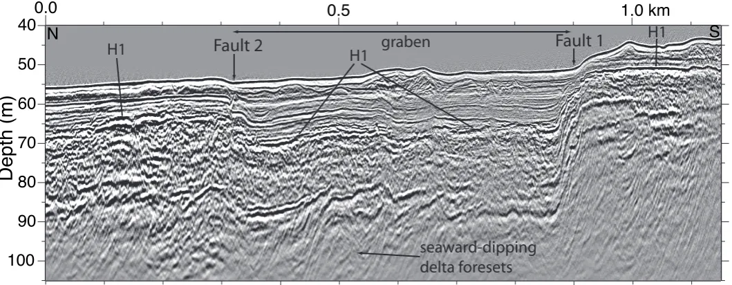
Figure 2. Prestack depth-migrated boomer seismic profile (Figure 1 for location) across the 331
Offshore Aigion fault system (OAF). Faults 1 and 2 bound the main offshore graben. 332
Distribution of other faults shown in Figure 3. Vertical exaggeration = 6–7 at seafloor. H1 is 333
transgressive flooding surface (10–13 ka) separating late Quaternary lacustrine and subaerial 334
deposits from Holocene marine deposits. 335
Figure 3. (A) Multibeam bathymetry of Offshore Aigion fault system (1.5 m grid) and 336
Holocene active fault interpretation (surface breaking faults solid, subsurface/blind (within 50 337
m of surface) faults dashed). Main faults (blue) labeled 1 and 2, major surface segments A, B, 338
C of fault 1. Photo shows possible recent scarp at coast (~38.25°N, 22.13°E). (B) E-W– 339
Phoenix
Meganitis
Selinous
Kerynites
2.5±0.71
4±2.46
3±1.46
2.3±0.47
3.5 ±11
5.5±1.5
4,2,5 WEF
EEF AF
OAF
SF
FF 1.7±0.51
SCF SEF
CGF
<<5?4,1
? ? ?
38°10’N
22°10’E
38°15’
CG
5±13
22°5’
5±12,5
AF-OAF system
Vouraikos
5 km
22˚00' 22˚30' 23˚00'
38˚00' 38˚30'
Gulf of Corinth
Peleponnese Aigion
[image:15.595.30.405.41.328.2]50
60
70 80
90 100
Depth (m)
Fault 2
H1H1
[image:16.595.31.561.52.258.2]trackline map
(no cdp's)
A C
B
A
1
2
38.25°
38.23°N
22.15°
22.14° 22.16°E
modern Selinous River debris flow deposits pockmark
cluster
Fault offsetting seafloor Subsurface fault
0 0.5 1 km
~30 cm SE
10
0 0.2 0.4 0.6 0.8 1.0 1.2 1.4 1.6 Distance along offshore fault trace (km) Displacement (TWTT
Sum, all faults Fault 1
~Displacement
(m)
10
0 100 200 300 400
[image:17.595.19.284.28.473.2]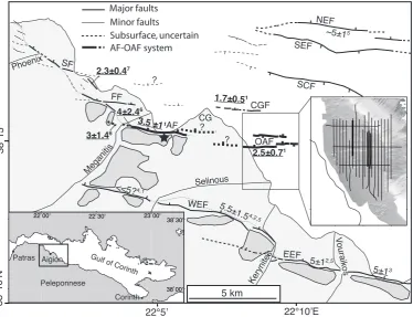

![Bis{decacarbonylbis[μ 2,2′ (phenylimino)diethanolato]ditin(II)ditungsten(0)(2 Sn—W)} hexacarbonyltungsten(0)](data:image/gif;base64,R0lGODlhAQABAIAAAP///wAAACH5BAEAAAAALAAAAAABAAEAAAICRAEAOw==)