BY
PAUL CROWTHER BSc. (hon) (Tas),
Grad. Dip. Comp. Stud. (CCAE), Grad. Dip. Admin. (CCAE) Dip. Teach. (TSIT)
DEPARTMENT OF COMPUTER SCIENCE
submitted in fullfilment of the requirements for the degree of Master of Science
This thesis contains no material which has been accepted for the award of any other higher degree or graduate diploma in any tertiary institution and, to the best of my belief, the thesis contains no material previously published by another person, except where due reference is made in the text of the thesis.
ABSTRACT
It should be possible to build expert systems which are capable of serving more than one purpose. Experts apply their knowledge in more than one way, for example they diagnose, they administer, they train, they schedule and they design using the expertise they have built up. Likewise it should be possible to build an expert system which can be used for more than a single task. The purpose of this study was to identify a problem domain where this could be done, pick an appropriate development methodology and build such an expert system.
The system which was finally chosen as a candidate for development was the evaporator section of the chemical recovery process at Associated Pulp and Paper Mills pulp mill at Burnie. The system was initially built using knowledge about fault diagnosis but with the aim of using it as part of the operator training process. The third purpose was to optimise the maintenance cycle and hence reduce down times of all or part of the evaporator process by investigating key features at set intervals. Fast prototyping was used for the development of the system with knowledge being obtained via interview with multiple experts, operators' manuals, trouble shooting guides and evaporator log sheets.
TABLE OF CONTENTS
page
ABSTRACT 2
LIST OF FIGURES 5
LIST OF PLATES 6
ACKNOWLEDGEMENTS 7
1 INTRODUCTION 8
2 BACKGROUND 10
2.1 EXPERT SYSTEMS AND CHEMICAL PULP MILLS 10
2.2 CHOICE OF PROJECT 15
2.3 SETTING OF THE PROJECT 17
2.3.1 OVERVIEW OF THE PULPING PROCESS 17
2.3.2 EVAPORATOR OVERVIEW 20
2.3.3 EVAPORATOR PROCESS DESCRIPTION 22
2.3.4 EQUIPMENT DESCRIPTION 24
3 METHODOLOGY 39
3.1 INITIAL ANALYSIS 39
3.2 KNOWLEDGE ACQUISITION 41
3.2.1 EVAPORATOR DOCUMENTATION 41
3.2.2 INTERVIEWS WITH EXPERTS 43
3.2.3 EVAPORATOR LOG SHEETS 46
3.3 CONSTRUCTION OF THE KNOWLEDGE BASE 47
3.4 TESTING 52
4 RESULTS 54
4.1 DIAGNOSIS COMPONENT 54
4.2 TRAINING COMPONENT 56
page
5 DISCUSSION OF RESULTS 58
5.1 MULTIPLE USE SYSTEM 58
5.2 DEVELOPMENT METHODOLOGY 60
5.3 SMALL A CHEAP SHELL 62
6 CONCLUSIONS 63
7 REFERENCES 64
APPENDIX A CAREER PATH FOR OPERATORS 66
APPENDIX B SAMPLE PAGE FROM THE FAULT FINDING GUIDE 69 APPENDIX C RULE DEVELOPMENT FROM AN INTERVIEW
TRANSCRIPT 71
APPENDIX D LOG SHEET 74
APPENDIX E TEST CASE SUMMARY 76
APPENDIX F SYSTEM EVALUATION BY THE TRAINING
CO-ORDINATOR 83
LIST OF FIGURES
figure page
1 PULP MILL RECOVERY INCLUDING WAO 18
2 LIQUOR FLOW DIAGRAM - EVAPORATORS 21
3 DETAILS OF AN El-iPECT 28
4 FINISHING PAN AND CALANDRIA 32
5 DETAILS OF A FALLING FILM EVAPORATOR 34
LIST OF PLATES
plate page
1 A GENERAL VIEW OF THE EVAPORATOR SECTION 25
2 FALLING FILM EVAPORATORS 26
3 PUMP AND CALANDRIA SYSTEM 27
ACKNOWLEDGEMENTS
I wish to thank the many people who made this thesis possible. First I would like to thank all those at APPM Burnie, specifically Paul Mole (who also took the photographs), Richard Ambrose, Penti Karkkainen and John Gray who acted as domain experts. Also Gert Kristensen and John Graves who acted as project coordinators at APPM. Thanks to Tony Purdy without whose permission and support the whole thing would not have got off the ground and finally Derrick Brown and his staff for library support. A special thanks to all the evaporator section operators who evaluated the system.
1 INTRODUCTION
The aim of this study was to investigate the use of a single expert system for multiple purposes. To this end a system was developed for training, fault diagnosis and system preventative maintenance. This system has been installed and tested at the Burnie Mill of Associated Pulp and Paper Mills (APPM).
There were also a number of sub-aims to the study:
Investigating the feasibility of using
multiple as against a single expert in the development of an expert system. There has been considerable debate about this point in expert system development methodologies. The view that will be put forward is that rarely will one person know everything about a problem domain.
Investigating the feasibility of developing
a medium sized expert system on a small scale (personal) system using a cheap commercially available shell. If this is viable it should reduce the traditional costs and risks of introducing expert systems into small and medium scale private enterprise.
The methodology used to develop the system will be discussed. The knowledge engineering techniques used will be stated and a description of how the knowledge base was built and tested will be given.
2 BACKGROUND
2.1 EXPERT SYSTEMS IN THE PULP AND PAPER
INDUSTRY
The forest resources industry including pulp and paper manufacturing is one of Tasmania's leading industries, both in terms of revenue and employment. There are firms operating in the State, Associated Pulp and Paper Mills (APPM) being the biggest with three mills located in Burnie, Wesley Vale and Longreach. In the south of the State the biggest employer is Australian Newsprint Mills (ANM).
The use of expert systems in these companies can be described as experimental. The system around which this thesis is based is the only one under development at APPM's Burnie plant and there is a second system under development at ANM. This situation is not confined to the forest based industries. Generally expert system are not used as production systems within Tasmanian industry.
cost for the development of an expert system. Beaverstock (1985) supports this view mentioning specialised work stations costing $100,000.
For the purposes of this study the kind of budget mentioned by Moore and Beaverstock was far too big. In the case of APPM an initial system had to be demonstrated as viable and cheap. An earlier study done for the company by
BHP was discontinued due to the cost of development being quoted in the region of that suggested by Moore. Since Moore's paper was written software and hardware resource costs for expert systems have dropped dramatically. Lukas and Keyes (1989) state that the era of large stand-alone computers running expert systems is over. Rather there is a trend towards smaller systems which will run on general purpose microcomputers using a relatively cheap commercial shell. This was the approach taken for this project. Personnel costs remained the major financial outlay. From APPM's point of view the domain expert's salary was the only major cost (about $40,000).
It is interesting to note some of Moore's closing comments from 1985 which give an idea of where APPM is placed in relation to expert system development.
stand alone computer expertise are the groups who can move ahead with success." (Moore (1985))
Other mills outside Tasmania have already embraced expert system technology for a variety of tasks, and specialist systems have been built. They appear to be relatively few in number, however. The most ambitious of these is the WEDGE (Wet End Diagnostic GEnius) system (Ritala et al., 1990, Paulapuro et al., 1990) which is a process-analysis system for the wet end process of a paper machine. WEDGE is used to analyse pressure and consistency variations and mechanical vibrations which affect paper quality. Changes in these factors are slow and occur generally as continuous drifts. The system uses expert knowledge to ._. predict when these 'drifts' reach a critical point and maintenance needs to be done. Analysis of past data was used to model the system and this was supplemented by human experts. The resultant model is now run off-line but its long term future is as an on-line system.
A second example is LES (Lathe Expert System) (Massey et al., 1989) which is designed to run on a microcomputer. It gives advice on problems associated with lathe operation and veneer quality in a plywood mill. This was developed to preserve expertise, make expertise available in remote locations and standardise the approach to problem solving. It was also justified as a training tool but its use in this guise was not stated. Multiple experts were used to develop this system which was implemented off-line on an IBM-AT microcomputer.
designed to train recovery boiler operators to adjust control variables so
MaXiMUM steam output, minimal emissions and safe furnace operations could be maintained. It is also being used in process operations where it provides expert advice to operators on complex operations such as start up and shut down. This appears to have occurred after its acceptance as a training system.
Other specific examples are much more difficult to find. The literature suggests areas in which the forest based industries could use expert systems. Bouchard et al. (1989) for example, suggests seven different areas including trouble shooting,
planning and scheduling, process engineering, process operations, quality control, process control and training. Lukas and Keyes (1989) present a similar classification but add that there should be a move to on-line and real-time systems. Few, however, suggest using one expert system for more than one purpose other than making general comments about uses in training. Boettcher and Herb (1986) came closest to suggesting systems should be developed for use in more than one role by suggesting that several expert systems could be interconnected to give process control benefits.
The situation is similar in other industries where most expert systems appear to have a maximum of two uses. For example an expert system being specifically developed for training and production work is hinted at in Gregor et al. (1990)
2.2 CHOICE OF PROJECT
A number of candidates for an expert system were investigated. These candidates had several features which were evaluated using criteria described by Slagle and Wick (1988) and Bouchard et al. (1989). Specifically the following issues were considered: the nature of the task, the availability of an expert and attitudes of users and management to computers and expert systems. Five potential systems were investigated. Two were rejected as being too big and ill-defined, two were discontinued after the development of an initial prototype and the fifth was developed into an operational system.
maintain evaporation rates extra steam is applied which means more coal is needed to generate that steam.
The evaporator section therefore met the requirement of being suitable for development of an expert system for multiple uses. It also met the requirements as a candidate for an expert system development in general terms. There were recognised experts in the area who could articulate their knowledge and were willing to participate in the development of an expert system. There was also some well-written documentation about the area available and the problems were well understood.
There was a demand for the expertise. The turnover of personnel in the section was high and although experienced operators were available not all were skilled in all aspects of the of the evaporator's operation.
2.3
SETTING OF THE PROJECT
2.3.1 OVERVIEW OF THE PULPING PROCESS
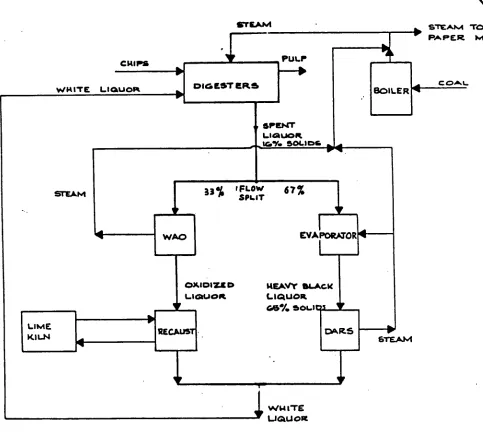
The evaporators are part of the chemical recovery process of the chemical pulping operation. The flow of materials through the pulping and recovery system is shown in figure 1.
The chemical pulping operation involves separating wood fibres by dissolving the lignin which cements and binds the soft wood fibres together. This done by cooking wood chips in digesters containing a strong alkaline cooking chemical. Dissolved lignin and spent cooking chemicals are washed from the cooked wood chips by injecting hot water into the bottom of the digester and withdrawing spent cooking chemical and lignin from the top. This mixture is known as spent black liquor.
The washed pulp is then further processed to produce white paper pulp from which fine paper can be made.
PULP
C OAL.
BOILER 4
V
EVAPORATOR
WAO
Page 18
STEAM STEAM TO
•-•40 PA PER MIL
DIGEST ERS
SP I QENT
L UOR
PP4 IG% SOLI OS
33 'FLOW
". SPLIT 6 7 %
CRIPS
%/F.% IT E LIQUOR
4-
OJOIUD NEAVY SLAW(
LIQUOR LIQUOR
GAM SOLIDS V
RECAUSTI CARS LIME
KILN 10, STEAM
[image:19.554.61.544.133.565.2]Ww ITE LIQUOR
FIGURE 1: PULP MILL RECOVERY INCLUDING WAO
The spent black liquor has three components : water, sodium compounds and organic material. The organic material is burnt to produce process steam. The sodium compounds are recovered and converted back into white liquor for re-use in the digester. This conversion is done by two processes, Wet Air Oxidation (WAO) and Direct Alkali Recovery System (DARS). The DARS plant is responsible for two thirds of the chemical recovery.
2.3.2
EVAPORATOR OVERVIEWFRom ouasretS
1111-ACX LIQUOR PIITLit
PINION ING
PAN
PAUL.T PLC CP PILOT CV ...
GLAND CI • tVIAabir
PRE.' CTAPORATORg
PALLING
(r.corucvartA-ru4G)
PORT GONG EN TRATOR A 0 , 'IN
LAA .CVAPORATOILS
HEAVY 61-kCS. I. IQ U01%. IMAPORATOR.
STOW-AG& TANK
[image:22.555.71.522.59.615.2]DARR
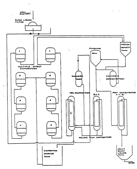
FIGURE 2: LIQUOR FLOW DIAGRAM - EVAPORATORS
2.3.3
EVAPORATOR PROCESS DESCRIPTIONPRE-EVAPORATORS
Black liquor is initially filtered (by the Black Liquor Filter) and then fed to the pre-evaporators which are of the falling film type. This concentrates the liquor to about 20% solids before it goes to the evaporator storage tank.
MULTIPLE EFFECT EVAPORATOR
Liquor is supplied to the two equivalent sets of multiple effect evaporators from the evaporator storage tank. In these evaporators liquor is concentrated to 42% solids before being sent to the medium density storage tank.
FINISHING PAN CONCENTRATOR
There are two parts to this system one of which is always on a wash cycle with liquor prior to entry into the pre-evaporator. The active part concentrates the liquor to 57%.
POST-CONCENTRATOR
2.3.4 EQUIPMENT DESCRIPTION
See plates 1, 2 and 3.
MULTIPLE EFFECT EVAPORATORS
Figure 3 shows an effect. It is one of four in each set and there are two sets. Liquor is heated in the calandria, a set of vertical tubes through which the liquor circulates. This is done by applying steam to the tubes where it condenses heating the black liquor in the tubes to a point where it boils. The vapour is then fed to the steam chest of the next effect in the set as the source of steam for further evaporation. Concentrated liquor is withdrawn from the bottom of each effect and sent to the next. Condensate is also withdrawn continuously from the effects. Non-condensible gas may come in with the liquor or steam and is removed from the steam chest through small vent lines to avoid accumulation.
PLATE 2: Falling film evaporators (centre rear). Vessel C is the left most of the
three. In the foreground are two effects of number 2 set of the multiple effect
.1.374443 NV dO
s
-
rtviaa
:£ H111101.331.1..no #.3111p1-1
Process steam is applied only to the first effect. As already stated the vapour produced is then used to heat the next effect. To do this the next effect must have boiling liquor at a lower temperature than the vapour to achieve heat transfer. For this to occur the effect must be operating at a lower temperature so the boiling point will be lower. This pressure gradient is achieved by a condenser steam ejector system on the fourth effect and the use of 210 l(Pa steam on the first effect.
Each set needs to be cleaned periodically to maintain efficient operation. The liquor side of the tubes get fouled with a build up of solidified black liquor. This is removed by boiling out the set with caustic soda. The steam side of the tubes get fouled with A.Q. (anthraquinone) scale which is removed by washing with dithionite.
ENTRAINMENT SEPARATORS (CYCLONES)
Vapour from the fourth effect passes into this device which removes liquor droplets from the vapour stream and returns them to the liquor extraction line from the fourth effect. Clean vapour passes on to the jet condenser in the case of No 1 set or the surface condenser in the case of No 2 set.
JET CONDENSER
The amount of water entering the system is adjusted manually to give maximum vacuum. The water comes from the condenser pit, the ejector system condenser and fresh water.
Non-condensible gases from No 1 set are also vented into the jet condenser and are then withdrawn from the system by the steam ejectors.
SURFACE CONDENSER
This consists of a bank of heat exchanger tubes in a mild steel shell. Fresh water flows through the tubes and vapour condenses on the outside. Condensate is pumped to No 1 hot water tank. Cooling water goes to No 2 condenser pit or the No 1 hot water tank. The amount going to either is controlled automatically. Periodic maintenance is required to stop organic slime building up on the water side of the tubes (caustic boil out needed) or A.Q. scale building up on the steam side (dithionite wash needed).
EJECTOR SYSTEM
CONDENSATE SYSTEM
Condensate is extracted from the base of each effect and cascades into the next. Condensate from No 4 effect is the total condensate from the system. As the condensate cascades from one effect to the next it flashes generating more steam which will heat the next effect.
Problems can occur when the liquor level in an effect becomes too high and there is carry over of liquor or froth into the next effect with the vapour. When this happens the condensate is contaminated and is useless for washing the brown stock (pulp output from the digester) and must be directed to the evaporator sump (drain).
Dumping condensate is costly both in terms of loss of thermal energy and caustic from the liquor. Problems here must be corrected as soon as possible.
FINISHING PAN - CALANDRIAS
---)—Vapor
F IN IS 14ING PAN
Impingement baffle for separating , liquid and vapor .
Product
-SOLIDS ;BLACK LIQUOR)
CAL.ANDR/A
moo lkfc.. • Vent Steam
[image:33.556.119.507.102.558.2]inside tubes tubes Condensate
FIGURE 4: FINISHING PAN AND CALANDRIA
EVAPORATOR TRAINING MANUAL (Associated Pulp and Paper Mills,
1986a)
tifo tu 1••■ cowl ITY
Liquor is pumped through the calandria (horizontal tube heater) at relatively high velocities. The tubes are surrounded by high pressure condensing steam. Liquor does not boil in the calandria because of the high circulation rates and pressure. The liquor then goes into the flash vessel (the finishing pan) where the vapour flashes off.
If liquor boils in the tubes solids will be deposited and heat transfer will be reduced which will affect performance. Deposits do build up which is why the calandria are regularly placed in wash mode.
Steam generated by this system is reused by sending it to the first effect of the multiple effect evaporators. Liquor droplets in this steam are removed by a cyclone and returned to the finishing pan vessel.
FALLING FILM EVAPORATORS
Demister Vapor Outlet
Liquor Circulation 'Inlet
Liquor Distribution System Noncondensable
Vent Outlets
Live Steam Inlet
Live Steam Condensate Outlet
Liquor • Circulation
Outlet!
[image:35.553.136.515.55.661.2]Heating Element Bank
FIGURE 5: DETAILS OF A FALLING FILM EVAPORATOR
EVAPORATOR TRAINING MANUAL (Associated Pulp and Paper Mills,
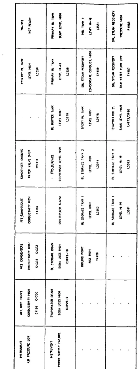
FIGURE 6: EVAPORATOR ALARMS: DETAIL OF ALARMS SHOWN IN
PLATE 4
EVAPORATOR TRAINING MANUAL (Associated Pulp and Paper Mills
OPERATION
BEATING SURFACE
The heating surface in each vessel consists of a bank of twenty heating elements made from two stainless steel plates. Condensing steam flows up into the elements and liquor flows down the outside (in a falling film) where it is boiled. Liquor is continuously circulated by a pump, product liquor being bled off from the pump discharge.
STEAM SYSTEM
Steam to vessels A and B is supplied through two thermocompressors. Thermocompressors are used to improve steam economy. The vapour boiled off in vessels A and B is used to supply a common header. Part of this is reused and the rest is used as the heating medium in vessel C.
Condensate flows from the bottom of the bank of elements into a condensate tank. Vessel A and B condensate tanks feed into the larger vessel C tank from where it is pumped into the process hot water tank No 1.
If the condensate is contaminated (liquor has got into the condensate) an automatic conductivity probe will open a dump valve to the drain as well as setting off an alarm. Once again the cause of contamination should be diagnosed quickly.
VACUUM AND NON-CONDENSIBLE GAS SYSTEM
3 METHODOLOGY
3.1 INITIAL ANALYSIS.
The reason for the choice of the Evaporator Section as the basis for this study has already been stated in section 2.2. However a more in-depth statement of the initial analysis needs to be made to show why this particular area was deemed
suitable for the development of an expert system that could be used for multiple purposes, how the problem boundaries were defined and why the development tool used was chosen.
This study was the first serious attempt by APPM to introduce an expert system, therefore there was a need to make the project successful and demonstrate wider applications to management (Bonnet etal., 1988). The system therefore had to be small enough to be developed by a small number of people but significant enough to impress management and users.
The boundaries of the problem were easy to establish as the evaporators have a single product input (weak black liquor) and a single output (heavy black liquor). The other inputs of consequence are production steam and cooling water. The only other output is condensate which is later used for washing wood pulp from the digestor.
The initial analysis then followed the sequence identified by Harmon et al.
(1988). First the type of event that initiates the problem solving sequence was identified. In the case of the evaporators this was either an alarm sounding or deterioration in performance of one of the evaporator components to the point where some maintenance had to be done (that "point" turned out to be difficult to identify). Secondly the end of the task had to be identified, which was the bringing of the evaporator back to optimum operation. This was determined in early briefings and tours of the plant.
The approach of Harmon et al. is then to identify in general terms how the
problem was solved. In the case of the evaporator project it involved gathering data throughout the problem solving process rather than having all data on hand initially. This lent itself to a primarily backward chaining model.
Lastly a development tool had to be chosen before prototyping could begin. Due to financial constraints a rule based shell was decided on despite a frame based system having attractions in the systems training role.
VP Expert version 2.1 (Paperback Software International, 1989) was chosen due
3.2 KNOWLEDGE ACQUISITION
Knowledge for the system was acquired in three ways: APPM documentation
Interviews with experts Log sheets
3.2.1 EVAPORATOR DOCUMENTATION
The original prototype was based heavily on written material in the form of an Evaporator Training Manual (Associated Pulp and Paper Mills, 1986a) and a trouble shooting guide (Associated Pulp and Paper Mills, 1986b) an example page of which is in appendix B. Initially the diagnostic guide was used to develop rules and divide the evaporator section up into three logical areas: The multiple effect evaporators, finishing pan and falling film evaporators. Within these three several major subareas were identified around which the coarser or initial rules were developed. At first everything was in a single knowledge base. This was slow, unwieldy and difficult to maintain, even at the early stage. Waterman (1986) suggests that if a knowledge base reaches this stage it should be reassessed and redesigned. Therefore the rules were split into three knowledge bases which were equivalent to the three logical areas. Later a fourth knowledge base was added to deal with the alarms on the falling film evaporators.
Training Manual was used mainly to add justification messages to the knowledge base. Operators could then ask why questions were being asked, and receive information about correct pressure, flow and vacuum levels. The detailed justification was also added to give explanations when the system was used in its
training role.
3.2.2 INTERVIEWS WITH EXPERTS
Using the information gained from reading both the Evaporator Training Manual and diagnostic information and developing the initial prototype, a series of knowledge engineering interviews were arranged with the expert to sort out obvious deficiencies in the system. The initial interview was unstructured (Welbank, 1990), that is getting to know the expert and a general idea of how he solves problems.
After the first two interviews the primary expert left the company and Tasmania. Fortunately there were two other experts willing to help, one of whom had the added advantage of being in charge of evaporator training as well as providing expert trouble shooting advice.
An important development at this stage was the company's decision to review the training procedures, Evaporator Training Manual and the trouble shooting manual as a separate project in the evaporator section. This was probably the key to success of the entire expert system project as this redevelopment and the development of the expert system then started to run in parallel, with information elicited by the knowledge engineering interviews being included not only in the expert system but also in the new Evaporator Training Manual and associated documentation. These interviews tended to be prompted (Vsfelbank, 1990) using specific cases or documentation as a basis for discussion.
For example incorrect symptoms were being associated with particular incidents. Specifically flash over could be caused by low vacuum according to the fault finding guide. This was wrong, the correct information being that flash over could be a problem when vacuum was reestablished. The associated rule was deleted and warnings added to all output screens advising that a vacuum needs to be reestablished. An example of a problem in the Evaporator Training Manual was an incorrect description of part of the multiple effect evaporator system where a non-existent heat exchanger was shown. This problem came to light when questions were posed about its purpose. Another example of problems being detected was when the expert used a design drawing to illustrate a particular flow and discovered a pump in a closed circuit feeding itself. In the same interview using the same diagram two pumps appeared to be connected to each other by their output lines. The information gained at these interviews was therefore important to incorporate in the expert system and also to update the Evaporator Training Manual and other documentation.
A third expert was used to verify the information given by the other two experts. This person was a senior operator rather than an engineer and provided more operational information about the evaporators. Some of this information was gained directly from interview, the rest after he used the prototype expert system and discovered either problems or omissions. His knowledge allowed environmental information to be added to the system. For example heavy rain causes the western condenser pit to flood setting off the conductivity alarm. An example of an interview with this expert and the way a rule was developed and finally used in the system is in appendix C.
3.2.3
EVAPORATOR LOG SHEETSAn example of one of these forms is in appendix D. Initially a set of log sheets from a three month period was obtained and examined. Although not providing explicit details as to how problems were diagnosed (except in the case of a major failure), they did give an insight into the maintenance cycle. That is performance data could be traced to the point where maintenance was required. This point varied depending on the shift running the evaporators at the time, suggesting that a uniform method of determining when maintenance is due be introduced. A shut down usually means loss of production or overloading another evaporator element, however running an evaporator that needs maintenance is costly in terms of steam production and ultimately the unit takes longer to clean.
The log sheets also served as a useful basis to ask questions when interviewing the experts. It was by studying the log sheets that it was discovered that some parts of the evaporator readings were taken in pounds per square inch (PSI) and others in kilopascals (kPa). In the case of the Multiple Effects, number one set used PSI, number two set kPa, requiring extra rules and conversion equations to be added.
3.3 CONSTRUCTION OF THE KNOWLEDGE BASE
The knowledge base was built using VP-Expert, a cheap ($350) expert system shell. The final system consists of 265 rules contained in four knowledge bases.
Construction of the knowledge base was very dependent on the way the shell's inference engine arrives at a conclusion. This also affected the usefulness of the final system in relation to its use in multiple roles. To demonstrate this one needs to look at the construction of a VP-Expert program and the way its inference engine works.
A VP-Expert knowledge base consists of three main parts. First there is a procedural section referred to as the actions block. This is processed like a procedural program and allows initial facts to be set, messages to be displayed and loop controls to be implemented. It also specifies the objective of the consultation (the goal variable) with a FIND command. The evaporator expert system has a single goal variable which is the problem affecting the equipment.
likely possibilities are checked first and unnecessary rules are not fired or unnecessary questions asked.
The other consideration in the ordering of the rules relates to the seriousness of a problem. Hence rules about significant failure problems (for example those which set off alarms) are checked before rules which predict maintenance and hence appear earlier in the knowledge base.
To ease maintenance of the knowledge base, rules are grouped by problem type. For example there are groups of rules which deal with pressure problems, others with vacuum problems. This grouping is not rigid however as not all diagnostic criteria fall into discrete areas. When groups of rules were set up, any rule that could be placed in several locations was placed with the group of rules which require its conclusions first.
Within these rule groups the first rules are the ones which suggest there is no problem and the last are rules for which the problem is unknown. For example in the Multiple Effect knowledge base after alarms are checked the next rule containing a goal variable is:
IF Problem_Area = Multiple_Effect AND Evaporation_Rate >4 AND Set = No_l AND
Vacuum_Level > 22 AND
Liquor_Carry_over = No_Alarm AND Dome_Pressure = OK AND
Pan_Pressure = OK THEN
Problem_Solution = NONE
conditions in these rules are met a message confirming normal operation is displayed. There is a similar structure in the Falling Film and Finishing Pan knowledge bases. Situations where there is a problem but no known solution often require more investigation and hence have the longest rules or largest number of rules to fire. To avoid unnecessary questions these are placed last in a group.
Also important is the order of the variables being checked in the condition part of the rule. Those variables which are most discriminating and easily measured are placed first in a rule. Hence variables of pressure and vacuum need values early in the consultation so rules containing deep knowledge about the plant's operation are fired early in the consultation and unnecessary search paths are then eliminated. For example the following rule from the multiple effect evaporator knowledge base sets several variables to no, representing situations which cannot occur in the case of poor heat transfer.
IF Problem_area = Multiple_Effect AND M_E_Problem = Low_Vacuum AND Poor_Heat_Transfer = YES
THEN
DISPLAY "Investigating cause of poor heat transfer" Probable_Cause = P_H_T
Ejector_Problem = NO Air_Lealcs = NO
It is also important to order the variables in a way that reflects the expert's reasoning so there is a logical path to queries when the system is being used in a training mode. This will result in the order of user questions being the same as the experts' search for facts.
These are displayed when the inference engine finds a variable for which there is no value in the knowledge base. Unless a reading is required the range of user responses is displayed as a menu. This was done for ease of use, and also, within the training role to make a trainee aware of the various symptoms they could meet.
Explanations are attached to the rule requiring a value for a variable, not to questions, and are activated by a user selecting the WHY option. Hence a question can be activated by different rules in different consultations causing different explanation to be shown because the context and significance of the question may have changed. From a training point of view this is important.
Conclusion messages are attached to the rules containing goal variables because of the large number of different messages that need to be displayed. Hence the goal variable's final value is important only to the extent the appropriate message is shown. The value of the goal variable is never displayed to the user. These concluding messages were a primary consideration when building the knowledge bases and reflected its multiple uses. As a result there are three types of final messages. The first type is displayed when a problem is found. In these cases a recommended course of corrective action is given. A message of this type would be expected in either a diagnostic, training or a maintenance consultation.
The third type of message is displayed when no problem can be found. That is if the evaporators are operating within their performance parameters. This type of message would generally be seen when the system is being used for maintenance.
Several problems encountered in using the selected shell do, however, need to be mentioned.
The major problem encountered in building the system was with part of the explanation facility. The 'WHY' option presented no problems. This displays the text in the 'BECAUSE' part of a rule and is activated when a user wishes to see why a particular question is being asked. As already stated a lot of time was spent on this aspect because of the system's training role.
The 'HOW' explanation facility which is supposed to state how a conclusion was reached is not very good and is confusing for novice users. To overcome this problem the system was designed to display justification messages as it chained through the knowledge base and reached intermediate conclusions during a consultation. The challenge was to make these messages as concise as possible to avoid unnecessary blocks of text appearing during a consultation but at the same time justifying why a particular action was being taken. User feedback suggests this aim has been achieved.
3.4 TESTING
Testing was carried out throughout the development of the system (Harmon et al. 1988). Initially this was to ensure the system gave correct results and degraded gracefully at the edge of its knowledge domain. The following message is an example of what is displayed in such a situation :
"The cause of high pressure in No 1 pan steam chest in the M.E.E. sets is poor heat transfer. However a more specific diagnosis cannot be made given this systems knowledge of the M.E.E. sets. Please note the problem and its solution so this system can be updated".
At certain stages when part of the system was near completion an extensive set of tests were made to check the various paths and solutions in the system. This was done by an evaporator operator and one of the domain experts who independently systematically worked their way through the system noting solutions and problems as they went. Problems were investigated with the domain experts and fixed. In this way the diagnostic and maintenance aspects were checked.
were corrected. A summary of the test data used in these tests is given in appendix E.
The systems in its training role was tested by the Pulp Mill Training Co-ordinator who used a selection of the data. The intermediate justification messages and the 'WHY' facility messages were reviewed and in some cases modified.
4 RESULTS
The development of an expert system which could be used for multiple purposes has to be evaluated in terms of how well it meets the requirements of fault diagnosis, training and maintenance.
4.1 DIAGNOSIS COMPONENT
Test data was derived from the evaporator log sheets. All incidents between 17 April 1990 and 23 August 1990 were tabulated and applied to the system. There were a total of 90 incidents of which 42 were of a maintenance nature and the remaining 48 of a general nature. The date, unit, problem and critical pressure readings are recorded in appendix E. Those incidents which fell into the general category were used to test the fault diagnosis system. At the start of the testing period the system gave correct responses in all but two cases. In those cases the system was examining the correct fault area but responded with a message that it could not find the fault given its current knowledge of the system. Extra rules were then added to overcome this problem. By the end of the testing period the system was giving a correct diagnosis in all cases.
For fulal verification the test data was given to two other senior operators who then repeated the process described above. The system performed with no adverse reaction from the operators.
It is impossible to state that the system is 100% correct as new rules are being added continually. This is due to new problems arising as the equipment ages and also as a result of modifications to the equipment, for example the addition of new valves and sensors. Therefore the expert system, although out of the prototype stage, is still under active development.
4.2 TRAINING COMPONENT
In its role as a training system the expert system has been used in conjunction with other training materials which included a video disk and microcomputer based learning package as well as notes and manuals. This material has been compiled by APPM and packaged by Box Hill TAFE. The video disk and microcomputer part of the learning package was a Canadian production which gave basic but not specific information on evaporators. Since all chemical pulp mills use different configurations of evaporators (including valves and pipes) the expert system has been used to give training specific to the Burnie plant by acting as an intelligent tutor. The course is split into two parts, a knowledge module and a skill module. In both of these the trainee operator is required to do self help questions. If they have difficulties finding a solution they use the expert system to step them through the problem.
A data base of problems (which have been run through the system) has been established and a selection of these is given to the trainee at the end of training. They are asked to provide solutions which are then checked against the system solution.
4.3 MAINTENANCE COMPONENT
Approximately half of the incidents reported in the evaporator log sheets could be regarded as maintenance problems (42 incidents). Of these the majority were caustic boil outs (39, of which ten were for the falling film evaporators, the remainder the multiple effects) and the rest dithionite washes (multiple effects only). These were further investigated by tracing back through the log sheets to determine where the expert system would have suggested maintenance was required. The system suggested maintenance was required on average four days before it was actually carried out in 26 cases and agreed with the operators in the remaining cases. The worst case in the test period was when the system suggested a caustic boil out on the 6th May, but one was not done until the 21st May by which time evaporation rates were extremely low. In another case on 3rd September 1990 (not in the formal test period but using a real-time incident) the system suggest a dithionite wash while the operators performed a caustic boil out. The system turned out to be correct.
Despite its performance as a predictor of maintenance and managements enthusiasm for its use, this usage of the system was the only segment not to be implemented except as an extension of the diagnosis component. Management's reason for not wanting to implement this usage of the system was they wanted the recommendations in appendix F on standardisation of instrumentation in the evaporator section to be implemented first. This is expected to take about 12 months. When these instruments are installed they want the system to not only predict problems but also to log readings. This is technically feasible as VP-Expert will
5 DISCUSSION OF RESULTS
The results of this project have been presented in terms of how well the expert system performed in its three roles. What now needs to be evaluated is the system's advantages and performance in its integrated role of diagnoser, training package and maintenance predictor. Certain aspects of the development methodology also need to be discussed, particularly the use of multiple experts and the practicality of developing a medium size system on microcomputer-based cheap shell.
5.1 MULTIPLE USE SYSTEMS
Most expert systems are developed with a single use in mind. They are used for diagnosis, process control, process engineering and training. Generally the only multiple use involved is in the secondary role of training. Development of a system for multiple roles however has advantages where those uses overlap. In the evaporator expert system the interface (as well as the knowledge base) being used in the training package is identical to the one trainee operators will be using when they are on the job. The system therefore not only trains them in the operation of the evaporators in a non-threatening environment but also teaches them how to use the system itself.
To do this no attempt was made to model the trainee's cognitive behaviour such as the keyboard tutor of Amato and Tsang (1989) . Rather the approach taken by Gregor et al. (1989) was adopted. This assumes that all trainees are at a similar level
The diagnosis and maintenance prediction components are complementary to each other and therefore were easier to integrate than the training component. The maintenance prediction part is designed to be used at a fixed interval (once every two hours, the same as current manual logging) so an optimal maintenance cycle can be implemented. However if some other part of the evaporator system starts to give problems this will be picked up as part of the standard consultation. The system's rules cannot distinguish between maintenance and general problems rather key indicators on the evaporator instrumentation are checked.
5.2 DEVELOPMENT METHODOLOGY
The system was developed using a traditional prototyping methodology but with the use of multiple experts. Considerable debate has raged over the use of single or multiple domain experts in the development of expert systems (Rantane, 1990, O'Neill and Morris, 1989). This system was initially developed using a single expert, but after he left APPM, it was completed using two and at one stage three experts. More knowledge was elicited and elicited more easily while working with multiple experts than with the single expert. A reason for this may have been that the original expert was planning to leave anyway and may not have been motivated to do any major work before he left. The three who replaced him on the other hand were motivated as they were also responsible for a major review of the evaporator operator training course and the evaporator documentation including manuals and blueprints. As a result the knowledge engineering and the redevelopment project complimented each other. Personality also played a part. After the primary expert left the three remaining experts did not have an identifiable leader who could be regarded as the primary expert. Rather they worked together to solve problems and each had an area where they had more expertise than the others. For example one of the experts was also in charge of training. His knowledge of how to explain things to trainees as well as his experience as a process engineer helped considerably in the development of the training component. A second expert had responsibility for the electronic and monitoring devices, the third was an experienced supervisor with in depth knowledge of day-to-day mechanical problems.
5.3 CHEAP MICROCOMPUTER BASED SYSTEMS
The evaporator expert system was successfully developed with a cheap shell using a microcomputer. This is unusual compared with cases quoted in the literature, especially from the mid 1980's (Beaverstock, 1985). The result was more in line with Lukas and Keyes (1989) prediction that more systems would be developed on general purpose microcomputers using cheap shells. Examples of this prediction coming true can be seen in other industrial settings (Freeman et. al., 1990). However
although this was developed on a microcomputer it was relatively small (40 rules) compared to the evaporator expert system.
6 CONCLUSIONS
The development of an expert system for multiple uses is both practical and desirable. In the case of the evaporator expert system the fields of diagnosis, maintenance and training were covered. The advantages of this approach is that trainees get to train on a system they will use on the job, overlap between maintenance and diagnosis are covered by common rules and a single knowledge base needs to be maintained.
Such a system can be developed on a microcomputer using a cheap commercially available shell. This reduces the risk to the company whose main financial cost becomes that of the personnel involved. If major cost savings can be shown, as was the case with the evaporator expert system and the hands-on users are enthusiastic about its use, it stands a good chance of success.
7 REFERENCES
AMATO, A.H. and TSANG, C.P., (1988), "Student Modelling In A Keyboard Scale Tutoring System", Proceedings of the 2nd Australian Joint Conference on Artificial Intelligence, Adelaide, pp. 57-72.
ASSOCIATED PULP AND PAPER MILLS, (1986a), Evaporator Training Manual,
manuscript.
ASSOCIATED PULP AND PAPER MILLS, (1986b), Evaporator Trouble Shooting Guide, manuscript.
BEAVERSTOCK M., (1985), "Artificial Intelligence for Mill Operators: Evolution of Revolution", Paper Industry Management Association Magazine, 67, pp. 21-23.
BOETTCHER W.E and HERB S.M., (1986), "Artificial Intelligence for Distributed Control", Southern Pulp and Paper, 50, pp. 32-33.
BONNET, A. HATON, J-P, TRUONG-NGOC, J-M, (1988), Expert Systems, Principles and Practice, trans. J. Howlett, Prentice-Hall, U.K.
BOUCHARD D.C., VADAS 0., KOWALSKI A. and LEBENSOLD J., (1989), "Picking expert system applications like an expert", Tappi Journal, 72, pp. 87-92.
FREEMAN, N., KEMP, T. AND LEGG, J., (1990), "The Development of an Operator Guidance System for Lead Blast Furnace Operations", Proceedings of the 4th Australian Joint Conference on Artificial Intelligence, Perth, pp. 507-516.
FRIEDERICH, S., GARGANO, M., (1989), Expert System Design and Development, John Wiley and Sons, Canada.
GAMMACK J.G. and ANDERSON A., (1990), "Constructive interaction in knowledge engineering", Expert Systems, 7, pp. 19-26.
GREGOR, S.D., RIGNEY, H.M. and SMITH, J.D. ,(1989), "Designing an Expert System for Educational Application: the Interpretation and Explanation of Income Tax Consequences of Transactions in Property", Proceedings of the 3rd Australian Joint Conference on Artificial Intelligenc, Melbourne, pp. 2-13.
GREGOR, S.D., RIGNEY, H.M. and SMITH, J.D., (1990),
"CGTRules : A Commercially Available Expert System Providing for both Learning and Advice in Taxation Law relating to Capital Gains TWA", 4th Australian Joint Conference on Artificial Intelligence Workshop Proceedings, Perth.
HARMON, P., MAUS, R. and MORRISSEY, W. (1988), Expert Systems: Tools and Applications, Wiley and Sons, New York.
MASSEY, J.G., THOMPSON, R.P. and DEHOOP C.N., (1989), "The utility of expert systems to the forest products industry" Forest Products Journal, 39, pp. 37-
40.
ME'FZ, J, (1986), "Improving the safety of recovery boilers" Paper Industry Management Association Magazine, 63, pp. 28-31.
MOORE, R. L., (1985),"How will expert systems enter the pulp and paper industry"
Paper Industry Management Association Magazine, 67, pp. 24-25.
OLSON, R.J. and RUETER, H.H., (1987), "Extracting expertise from experts: Methods for knowledge acquisition", Expert Systems, 4, pp. 152-166.
O'NEILL M. and MORRIS A., (1989), "Expert Systems in the United Kingdom: an evaluation of development methodologies" Expert Systems, 6, pp. 90-98.
PAPERBACK SOFTWARE INTERNATIONAL, (1989), VP-Expert version 2.1: Rule Based Expert System Development Tool, California.
PAULAPURO H. RITALA R. and PENTTINEN I., (1990), "Artificial intelligence in Pulp and Paper applications", Paperi ja Puu - Paper and Timber, 72, pp. 572-577.
PEDERSEN K., (1988), "Connecting Expert Systems and Conventional Environments", Al EXPERT, 11, pp. 26-35.
RAMESH T.S., SHUM S.K. and DAVIS J.F., (1988), "A structured Framework for efficient problem solving in diagnostic Expert systems", Computing in Chemical Engineering, 12, pp. 891-902.
RANATANEN, J., (1990), "The practice of knowledge aquisition and analysis: A survey of the experiences in Finnish A.I. projects", Workshop Proceedings of the 4th Australian Joint Conference on Artificial Intelligence, Perth.
RITALA, R. PAULAPURO, H. PENTTINEN, I. VALTONEN, E., (1990), "Knowledge-Based Systems for Advanced Process Analysis", Procedings of the 24th EUCEPA Conference, Stockholm, Sweden, pp. 45-63.
SLAGLE, J.R. WICK M.R., (1988), "A method for evaluating candidate expert system applications", Al Magazine, 9,
pp. 44-53.
WATERMAN, D.A., (1986), A Guide to Expert Systems, Addison-Wesley, Reading,
Massachusetts, pp. 135-136.
WELBANK M, (1990), "An overview of knowledge acquisition methods"
APPENDIX A
L6 115% SEPA B/P OPN. ADV. DIGESTER B/P OPN. OARS SENIOR OPERATOR
L5 110%
EPA B/P TESTING DIGESTER B/P TESTING WAO SENIOR OPERATOR
OARS 1
L4 105%
CAPA EVAPORATORS EVAPORATORS
S/C OPERATION S/C BLEACHING WAO
L3
LIME KILN ' WASHING • SENIOR
RE-CAUST.
MOL MAKING S/C REFINING LIME KILN
WASH & SCREEN RE-CAUST. ROT. OP.
BLEACHING AND FIBRE RECOVERY .
BLEACH CHEMICALS STREAM STREAM
STREAM
L2 95%
WOODROOM ATT. POTMAN EVAP. ASST. WOODROOM OP. RINCA 2
SEMI ASST. CHIP SCREEN ATT. DARS 2 CLEANER
L1 90%
ASSISTS IN JOBS AS PART OF A TEAM OR WORKS UNDER DIRECT SUPERVISION
LO ON COMMENCEMENT 85%
APPENDIX B
PROBLEM CAUSE ACTION CRECK LIgr
MME SETS - NO. 2 SET 5. Liquor carry
over with vapour
Excessive foaming
Liquor levels in Effects too high Loss of extraction from first or fourth Effects.
Loss of vacuum
Tube(s) leaking in the Calandria of Effects
CHECK alkalinity, liquor temperatures, air leaks
Bring levels back into control by adjusting manual valves. CHECK extraction pumps
CHECK condenser and steam ejector operation.
CHECK overhead operating pressure for deviation from normal.
APPENDIX C
The following is an edited interview dialog between one of the experts, in this case Richard Ambrose (R) and myself acting as knowledge engineer (KB).
R: There is a problem in the system here, with the flashover information. KE: I took that from the fault finding sheets.
R: Yes well that's OK and most of it is right but there are a few things missing. We have alarms to detect flashover.
KB: I thought only the falling films had alarms.
R: No, we have alarms on the multiple effects as well. ICE: There is nothing about them in the manuals.
R: They are quite new. There is the condensate conductivity alarm and the drip tank conductivity alarm.
ICE: Does this detect flashover on both sets? R: Yes, there is one of each alarm on each set.
ICE: What could set off the drip tank conductivity alarm?
R: Generally the liquor level in the effects being too high, excessive foaming or the finisher flashing. .
ICE: I thought the finisher was a separate system.
R: Yes, it is, but its one of the main reasons for the alarms and you haven't mentioned it in your system.
KB: Why does the finisher flashing set it off?
R: Vapour from the finisher is used along with process steam to heat the first effect of both sets. If liquor carries over with that vapour the alarms on both sets go off.
ICE: So if both drip tank conductivity alarms are sounding it means there is flashover from the finisher?
KE: What is the usual cause of the finisher flashing?
R: Really the only cause is the post concentrator extraction pump being stopped which causes the liquor level in the finisher to rise to the point where it starts to flash.
The consultation then continued with information about the other alarms including the fact that rain can set off the drip tank conductivity alarm.
The above consultation was translated into the following knowledge base rule:
RULE LIQ_C_O IBA
IF M_E_PROB_AREA = D_T_C AND BOTH_ALARMS = YES
THEN
DISPLAY "The drip tank conductivity alarm is being caused by the finishing pan flashing over. This in turn is
probably caused by the post concentrator extraction pump being stopped causing the finisher level to rise. Since vapour from the finisher goes to heat the first effect the alarms both go off.—"
PROB_SOLUTION = FINISHER
APPENDIX D
•
•
•
EVAPORATORS LOG SHEET
°642 /717-
-44
7
.17/77TIME
PRE-EVAPORATOR No. 1 MULTIPLE EFFECTS No. 2 MULTIPLE EFFECTS FINISHER CONCENTRATOR POST
TO TAL EV A PO RAT ION HE AV Y BL ACK L IQU O R STO R AG E VII AC IN V1V3 W. A. O. SCREE N
1
FL OW VE SSEL A FL O W VE SS EL B FL OW VE SSEL C CON CENTR A TION IN C ON CE N TRA TI ON OU T EVA POR ATION N O.1 CAL.
PRE SS NO. 1 PAN PR E
SS NI
MO l d CO NCEN TR A TION OU T NO. 1 CAL. PRE SS N O. 1 PA N PRE
SS '3VA
NV d 17 'ON N I MO1 A CO NCEN TRA TI ON IN CON C ENTR A TION OU
T N
I MO -1 A CON CEN TRA T ION IN CON CE NTR A TION OU T E VA PO R A TIO N in o MO1 d CO N CEN TR A TI ON OU T E VA PO RA TION
0800 11 3 6 3S /05 r._47 ? S- -7A0 lap- 37 L-3 ,,313 ,..23' ... ..21 4: 7 4-9 c5 S;-L-' .67 571,, t -
V
1
4 --ro 7;757149 /30 At ..S.., 1000 f&c, p,_.; 3it- 35 071 ‘2.q 2,, rpzo 10.4 35 _)/ f ;W. 9.,,Z. 35 47,;.3zi “•6. 1/
6... -;--,
IS-g
fir,47-2.,04- g.31 /20 Al1200
(3
.
o
17/.75
d7
o
lioq ag 48-
-
1/
,
3
,
7
0.2e
1 zy 9-Z-as
ii-Ijc6 3
,
s
t
i4i
62(07 ,5-..sr t 037 /Hi,- ('1400 8.0 i .: ,)?
91 iI73_
7 ,zo j-10 Z ,',23 ,*9 4:37,/c4 0 Z(4-_9.
v,28 .463 314 q„,/- 4 k4d.ai. it. g 16 1532_/1.71 /os1600 0 u c ;(S 2N IcXJ 7 4). c,11 7 Y 24 44 H. A:
41 a,
3 .‘ 214
36 324 E--C 3(7 64 .1?<; 11 •9 611 -cc; lig- Ss a
1800 rjso i„), 2•5 -'7 ile' 1.1.41 W /0,0
;Z.6
c.) ..f.,t)
/a
-0,. la 9.c
24- ,z,(1, 2,- :;/ 0 0 -c6,.
.3? i,-zi t 7 S V2000 /3.0 ---- /...ZS'
/Ir
. ?) 1 2ji ,,..w .4-..2...0 10 c,
-.2_ ir 7 .;.;;,'c '-2-1 g'‘ -2) ir4.? g'.-'. l'-.4 61 22. 1-19 61 .ic 1,z2/2r (9-0 Ai2200 1-0-
21 3I,321,),Y '
-
k1
2/ iorc x')
lib AI 1; R 12.js-,7 2J
ko Zzir'_ HO.64
,Illa
‘-Z ■•■•21 0 A/
2400 13.0 12‘ 29 3g s2.361 9,. 7
+,,,,
20 /6,0 ;Rq 4.2 3 013 +2- „Z
8
.
-8
/29 ito 242 g-,s- 56 212 -5.2 6 057 iosv/2 N
5z
0200 /3 ,C) a.s5 2? 31 -4 ( 2g 4-2 ,20 g), 0 28 3 I If -50 / g -1- 22. ? •7 2) ii' 3 4 c 57 - .5' ii-7 62 g*c6
4
.
9
,
5- 0.z242-4341 --C '
"
0400
B. o
I2• ):1 30 b2-‘S2-3 4
,
2 zo
WC 021 47 >7 022 2).C. ;26 Li 2 327vs-
i-i- 61 2-22 4-9 0'43 4,/f3 g 0 1"/ 0600 I•Co 12..5 2t 27 /.12 Zg *3 2 010,0 a6 0 0.
0
i)
7 r--4_ ,z,z,s.,4, ,1z, 4( 3 iioit
c. 4
6,3 0,51
irov (07•
7 A.M. INTEGRATOR READINGS NO. 1 M.E. STEAM SET BLACK LIQUOR- NO. 2 M.E. STEAM SET BLACK LIQUORL
FINISHER CAL. STEAM 4( / BLACK /5..LIQUOR / ,. .44 / i .,
FALLING
FILM STEAM
H .B.L. FLOW
7L
/21.8x
.
-
re
,
4-7 Si- /97 , f-oe /toe sor,),
AlAle z g- /6- = • ""7
COMMENTS
I, .
TIME
No. 1 SET No. 2 SET
PRESSURE & VACUUM TEMPERATURE °C PRESSURE & VACUUM TEMPERATURE °C
NO.
1
CALANDR
IA
+ PRE
SS— VA C N O. 1 PAN NV d Z ' O N N Vd CO N NV d VO
N HEA
TER NV d Z ON 0 _1. NV d L ON N O. 2 PAN NO. 3 PAN NV d 17 ' O
N HE
A TE R 7 ON + PRE SS— VA C N O. 1 PAN N V d Z ' ON N V d CON NV d ' ON HE A TE R CO NDENSE
R NV
d Z '
O N 0 1 N Vd L ON NV d Z ' O N NV d CO N NV d 4 ' ON
1 HE
ATE R CO NDEN SE R
l000 ,/ 3
t/
IY it)j() //,?.7/2 7. 706 c6q
“
bcb.
t(
-
(721
/-4
0
7 4
Q
s
91192
I
/1/ 79
1400 T7 ') 5- 1(0
ao
1800 a?
.
4/
____6 /y
-
al
/08 73 i?
"
2
_j
il
77 79 I/I f0337
/30
2200
A
-4 - I
-C 1
.. 1
1? cit-I P 6?
i
---1
-Z -I I Z
Iz
)
(
'I
7
7
‘-7
7
()Li
9
,
C
ck.
ig
//A
i1
2
-/0
.
3
/vs-
(0,04
E
.
7
9
0
62
,“
6S-
/?
0
139
139
0200 .
zg
4,2./L2c,
//6
9c
e3" 48
N
I
17
4-_
--i-A_
0
O
IC
7
22
:2'
0600 .;
zg 1.3
)3 A-Ci
Ile
cg
3g
7c
'M F 1950 - NVVPS 50059
h
"
CO
NOW>
N
-
vks /elo.
N/S.4
1
1
1
,4,4t
I
LL
1-30APPENDIX E
4
DATE UNIT PROBLEM/ACTION
17.4 No.1 M.E.Evap. No.4 Pan Level High
Caustic boil out. o /head press • + 9 s/chest 20psi No.2 M.E.Evap. Caustic boil out. o /head
press+ 1 0 s/chest 23psi 18.4 No.1 M.E.Evap. No.4 & No.1 Pan level high
21.4 No.2 M.E.Evap. Caustic boil out o /head press+ 10 s/chest 20psi 25.4 No.2 M.E.Evap. Surface Condensor vac low -65 kpa. 26.4 F.F.E.'s Pre-evaporators flashing over
incoming density 20.
27.4 No.1 M.E.Evap. Caustic boil out o /head press+ 2 s/chest 30psi Low vacuum
6.5 No.2 M.E.Evap. Low Vacuum -59 12.5 Low Vacuum -55 19.5 Low Vacuum -53
Evap.Rate 2.9 1/sec.
21.5 No.2 M.E.Evap. Caustic boil out o /head press+ 10 s/chest 24psi 22.5 No.1 M.E.Evap. Dithionite washed
F/Pan
. No.! M.E.Evap.
Level high Post Conc. S/Pump us. 23.5 No.2 M.E.Evap. Dithionite washed