DEVELOPMENT OF LIGHT PNEUMATIC ARTIFICIAL MUSCLE
(PAM) FOR POSITIONING TASK
This report is submitted in accordance with requirement of the University Teknikal Malaysia Melaka (UTeM) for Bachelor Degree of Manufacturing Engineering (Robotics
and Automation) (Hons.)
by
MOHAMMAD NUR SHAFIQ BIN AZMAN B051310317
941116-03-5913
Disahkan oleh:
_____________________________ ______________________________ Alamat Tetap: Cop Rasmi:
No 17, Jalan Kebangsaan 34, Taman Universiti,
81300 Skudai, Johor
Tarikh: _______________________ Tarikh: _______________________
*Jika Laporan PSM ini SULIT atau TERHAD, sila lampirkan surat daripada pihak berkuasa/organisasi berkenaan dengan menyatakan sekali sebab dan tempoh laporan PSM ini perlu dikelaskan sebagai SULIT atau TERHAD.
UNIVERSITI TEKNIKAL MALAYSIA MELAKA
BORANG PENGESAHAN STATUS LAPORAN PROJEK SARJANA MUDA
Tajuk: DEVELOPMENT OF LIGHT PNEUMATIC ARTIFICIAL MUSCLE (PAM) FOR POSITIONING TASK
Sesi Pengajian: 2016/2017 Semester 2
Saya MOHAMMAD NUR SHAFIQ BIN AZMAN (941116-03-5913) mengaku membenarkan Laporan Projek Sarjana Muda (PSM) ini disimpan di Perpustakaan Universiti Teknikal Malaysia Melaka (UTeM) dengan syarat-syarat kegunaan seperti berikut:
1. Laporan PSM adalah hak milik Universiti Teknikal Malaysia Melaka dan penulis. 2. Perpustakaan Universiti Teknikal Malaysia Melaka dibenarkan membuat salinan
untuk tujuan pengajian sahaja dengan izin penulis.
3. Perpustakaan dibenarkan membuat salinan laporan PSM ini sebagai bahan pertukaran antara institusi pengajian tinggi.
4. *Sila tandakan (√)
(Mengandungi maklumat yang berdarjah keselamatan atau kepentingan Malaysiasebagaimana yang termaktub dalam AKTA RAHSIA RASMI 1972)
(Mengandungi maklumat TERHAD yang telah ditentukan oleh organisasi/ badan di mana penyelidikan dijalankan)
SULIT
TERHAD
DECLARATION
I hereby, declared this report entitled “Development of Light Pneumatic Artificial Muscle for Positioning Task” is the result of my own research except as cited in references.
Signature : ………
Author’s Name : MOHAMMAD NUR SHAFIQ BIN AZMAN
APPROVAL
This report is submitted to the Faculty of Manufacturing Engineering of Universiti Teknikal Malaysia Melaka as a partial fulfilment of the requirement for Degree of Manufacturing Engineering (Robotics and Automation) (Hons). The member of the supervisory committee
are as follow:
ABSTRACT
ABSTRAK
DEDICATION
Special dedication to my lovely parents and sibling, my friends and all faculty members
ACKNOWLEDGEMENT
Praise to Allah the Almighty for giving the strength and hope to me while completing this project. Without any hesitation, I can say that the project that I had could not be complete successfully without the generous assistance of a number of people. I have an obligation to acknowledge all these people who gave valuable cooperation, assistance and advices to complete my project. First and foremost, my sincere gratitude goes to my respected supervisor, En Khairol Anuar bin Rakiman. Your kind advice, encouragement, guidance, time, attention and support towards realizing this works are greatly appreciated and indebted.
I would like to extend my appreciation to Universiti Teknikal Malaysia Melaka (UTeM), especially Faculty of Manufacturing Engineering (FKP) and to all academic and supporting staffs for assisting me in terms of facility and moral support. Not forgotten, I would like to give special thanks to Pn Shamsiah Hasita bt. Shafie for her advice, kindness, guidance, time and attention for me during completing this project at fluid power lab. Her supports and guidance are greatly appreciated and indebted.
TABLE OF CONTENT
ABSTRACT i
ABSTRAK ii
DEDICATION iii
ACKNOWLEDGEMENT iv
LIST OF TABLES viii
LIST OF FIGURES ix
CHAPTER 1: INTRODUCTION 1
1.1 Background 1
1.2 Problem Statement 2
1.3 Objectives 2
1.4 Scope 3
1.5 Expected Result 3
1.6 Conclusion 3
1.7 Chapter Remarks 4
CHAPTER 2: LITERATURE REVIEW 5
2.1 Light Pneumatic Artificial Muscle 5
2.1.1 McKibben Artificial Muscles 6
2.1.2 FESTO Air Muscle 7
2.3 Concept and Operation of PAM 9
2.4 Design of the PAM on Antagonistic System 11
2.4.1 Design of Actuator 12
2.4.2 Pneumatic System Components 12
2.4.2.1 Air Compressor 13
2.4.2.2 Pressure Gauge 13
2.4.2.3 Solenoid Valve 14
2.4.3 Antagonistic Setup 15
CHAPTER 3: METHODOLOGY 18
3.1 Flowchart of Overall Project 18
3.2 Experimental Flow Block 20
3.3 Design of Pneumatic Artificial Muscle 21
3.3.1 The Materials to Fabricate PAM 21
3.2.2 Fabrication of PAM 23
3.3 Design of Antagonistic Actuation 25
Figure 3.3: Testing setup of PAM 25
3.3.1 Material for Develop Antagonistic Actuation 26
3.4 Actuation System 27
3.5 Experimental Operation 28
CHAPTER 4: RESULT AND DISCUSSION 30
4.1 Pneumatic Artificial Muscle Positioning Task 30
4.2 Relationship between Lengths of Muscle with Diameter of Muscle 34
4.3 PAM Limitations 37
5.1 Conclusion 40
5.2 Recommendations for Future Works 41
5.2.1 Quality Material 41
5.2.2 Additional Apparatus/Software 41
5.2.3 Force and Pressure Sensor Devices 42
REFERENCES 44
APPENDIX A 46
LIST OF TABLES
3.1: Materials and descriptions for artificial muscle 21
3.2: The fabrication of PAM 23
3.3: Parts, materials and descriptions on developing antagonistic actuation 26
4.1: The parameter for PAM 31
4.2: Result of PAM 1 for positioning task 32
4.3: Result of PAM 2 for positioning task 33
LIST OF FIGURES
2.1: Various types of muscle actuators 6
2.2: Braided muscle, McKibben Muscle 7
2.3: FESTO air muscle 8
2.4: Dimensions of fully stretch muscle 8
2.5: Dimensions of completely contracted muscle 9
2.6: Constant load operation 10
2.7: Constant pressure operation 11
2.8: Pneumatic muscle actuator design 12
2.9: Air compressor 13
2.10: Pressure Gauge 14
2.11: Solenoid Valve 15
2.12: Antagonistic setup on linear and rotation 15
2.13: Equilibrium position as a function of gauge pressure ratio 16
2.14: PAM based antagonistic actuator 17
3.1: Overall flowchart for the project 19
3.2: The experimental flow block 20
3.4: Pneumatic diagram of actuator with artificial muscle 27
3.5: The initial position of actuation system 28
3.6: The arm position when pressure are set to the muscle 29
4.1: Length and diameter of complete muscle 31
4.2: Graph of pressure versus angle of rotation for PAM 1 32 4.3: Graph of pressure versus angle of rotation for PAM 2 33
4.4: PAM at rest and contraction 34
4.5: Graph of relationship between length and diameter of muscle 35
4.6: Graph of force against pressure 36
4.7: Tube start to deform/swell after pressure exceed 2.5 bar 37
4.9: Braided sleeve angle 39
4.10: Braided sleeve structure 39
5.1: Incremental encoder 42
CHAPTER 1
INTRODUCTION
This chapter give a brief explanation about this project, which starting with background of the project on Development of Pneumatic Artificial Muscles for Positioning Task. Next section on the problem statement of the project and followed by the objectives of this project. Based on both problem statement and objectives, the scope of this project can be identified in next section. Lastly the conclusion on the chapter also chapter remarks for all chapter.
1.1 Background
Actuator is the component that responsible for controlling the mechanism or movement of the system. They requires energy and signal to control it. Energy such as pneumatic, hydraulic or electrical voltage/current are required for the actuator. Pneumatic Artificial Muscles (PAMs) is one of the actuator that widely use in floor automation and robotics as well. One of the main reason why PAMs are widely use is the low weight and flexible behaviour. The shape is like human’s muscle membrane that can be inflation and contract. The main source of energy that operate the PAMs are compressed air (pneumatics). They are extremely light because of the membrane are their core element and they can transfer the exact amount of energy as cylinder do since they operates at same volume and pressure. This is the great potential to be used to power robots and use in automation field.
Basically, manipulation in manufacturing technologies which is major in robotics need actuator that can give high performance to weight ratios and high force/torque to weight.
1.2 Problem Statement
Automation and robotic field are being utilized highly in application that require human’s interaction. Human’s interaction needed in this field in order to ensure these actuator works properly, to program the system, maintenance on the actuator and replacement of actuator in the system. For manipulator in manufacturing field, lower energy consumption and higher performance at lightweight actuator is needed.
In order to overcome this situation, light weight and compliant manipulation are desirable. These requirements are needed because many conventional actuation system are often huge, heavy and typically use high firmness to achieve high effectiveness. PAMs are the actuator that can accomplish these elements while offering super lightweight ratios compared to those conventional actuators. This lightweight actuator can be used in applications of industrial robotic and also in applications of biomedical engineering.
1.3 Objectives
1. To fabricate the light Pneumatic Artificial Muscles (PAM).
1.4 Scope
The study will focus on the performances of PAM as the actuator in the system to control the mechanism and movement of the system. The implementation of antagonistic set-up to generate bidirectional motion either in linear or rotational motion will be used as the devices for PAM. Lastly, the angle of rotation of the arm will be recorded.
1.5 Expected Result
For this project, the expected outcome mostly the objectives of this project achieved successfully. The PAM can be fabricate and work properly in the system as the working principles. The muscle can contract when the pressurized air going inside. Lastly, the performance test of the muscle can be carry out and function properly.
1.6 Conclusion
1.7 Chapter Remarks
In Chapter 1 the introduction on the project are briefly discuss. From surrounding manufacturing environment, the problem statement are being define. From problem statement, objective to overcome the problem identified. Scope of study on this project are discussed to make the project more understand to complete. Chapter 2, the previous research on the project are being review completely. The requirement information on the project are get from previous experiment.
CHAPTER 2
LITERATURE REVIEW
2.1 Light Pneumatic Artificial Muscle
The growth era of robotics, through the mid-l980’s, was heralded by the introduction of automation into labor intensive industries. As with any market inefficiency, the easy problems were tackled first to maximize the return on investment. However, as the robotic industry’s growth declined in the 1990’s, it was clear the hard problems were left. One of the most challenging problems is the ability of a robot to productively interact in an uncontrolled environment. Human labor remains the most effective means of solving this problem. Biological muscle can be modelled as an actuator whose output force is a function of length, velocity, and level of activation. The muscle physiology literature contains numerous reports identifying the relationship between force and length during isometric contractions (constant length) when the activation is maximal (Klute et al. 1999).
radial and contract in the axial. If there is a load, the muscle will create axial contractile force. (Jizhuang et al. 2013).
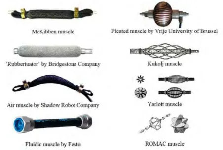
Pneumatic muscle is a resilient and contractile pulling actuator controlled by gas pressure. Since being first conceived (in the early 1930s) a considerable number of concepts of fluidic muscle actuators have been developed and some examples are given in Figure 2.1 (Šitum et al. 2015). There are two most common PAM that been used widely which are
[image:20.595.70.523.237.542.2]McKibben PAM, FESTO Air Muscle and The Shadow Robot Company Air Muscle.
Figure 2.1: Various types of muscle actuators
2.1.1 McKibben Artificial Muscles
length of the tube shortens due to the inextensible threads on braided mesh. When filling the inner tube with compressed air, the diameter of the rubber tube increases and the length shortens because of the inextensible threads. This is how the PAM generates a contraction force. On the other hand, releasing the compressed air from the PAM allows the elasticity of the rubber tube inside the PAM to return to its original shape (Urabe et al. 2015).
Figure 2.2: Braided muscle, McKibben Muscle (Daerden and Lefeber, 2002)
Braided muscles are constitute of elastic tube with gas-tight or bladder surround by sleeving (weave, braid, sleeve) as shown in Figure 2.2. The tube presses laterally against the sleeve when it been pressurized, the inside pressure balanced by braid fiber tension due to fiber curvature about the tube. The braid sleeve run helically about the muscle's length at an angle
Figure 2.1 shown the situation of PAMs when stretch, at rest and pressurized with air.
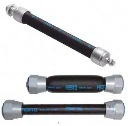
2.1.2 FESTO Air Muscle
Figure 2.3: FESTO air muscle (Deaconescu, 2009)
2.1.3 The Shadow Robot Company Air Muscle (30mm Air Muscle)
The 30mm Air Muscle is simple but strong actuator for generate pulling force. When filled with compressed air, the original length contracted about 37%. According to The Shadow Robot Company Ltd (2011) this muscle used to move a lever. One air muscle will pull the lever towards first direction, and a spring act to return the muscle to its original point. Two artificial muscles allow bidirectional motion of the lever, with significant force.
[image:22.595.80.525.537.674.2]These measurements as shown in Figure 2.4 are recorded when the muscle is fully elongate, with 50N applied load and 0 bar gas pressure.
Figure 2.5: Dimensions of completely contracted air muscle (The Shadow Robot Company Ltd, 2011).
From figure above. The dimensions are taken when 50N load applied to the muscle and pressurized to 3bar.
2.3 Concept and Operation of PAM
Daerden and Lefeber (2002) stated that PAM are contractile and linear motion locomotives drived by pressure of air. Their central component is a flexible enhance membrane attached at both ends to fixing along where the load transferred by mechanical power. As gas is reduced from it and the membrane go inflated, it bump outward, respectively. Together with this radial expansion or contraction, the membrane axially contracted and thereby pulling force generated on the load.
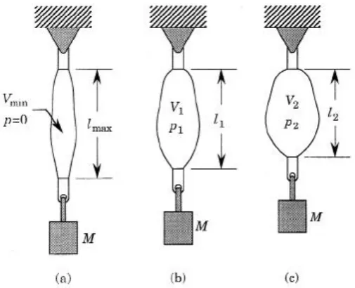
For both cases, PAM is fixed at one end and the other side are hang with mass. Figure 2.6 shown the mass M is constant and the difference in pressure across the membrane of PAM, the initial value at the gauge pressure is zero. At zero pressure, the volume by the membrane is minimal, Vmin and the length maximal, lmax. When PAM is pressurized to some pressure p1,
it will start to expand and the pulling force are created at the same time. The mass will be lift by the PAM until the generated force equal Mg. The membrane’s volume will extend to V1 and
its length contracted to l1. As we continue increasing the pressure p2, this process will
[image:24.595.171.424.303.508.2]continued. From this experiment two light actuator behaviour rules can be conclude: (1) length of PAM shortens by increase its volume, and (2) if compressed air pressure increased, muscle will contract against constant load.
Figure 2.6: Constant load operation (Daerden and Lefeber, 2002)
For the operation in Figure 2.7, kept constant value p at the gauge pressure, while reducing the mass load. For this operation, PAM will inflate and reduced in length. When the load is removed completely, as shown in Figure 2.7 (c), the membrane expand goes to its complete extent and the highest value in volume will reach Vmax, minimal length lmin, and pulling force