promoting access to White Rose research papers
White Rose Research Online [email protected]
Universities of Leeds, Sheffield and York
http://eprints.whiterose.ac.uk/
This is an author produced version of a paper published in the Proceedings of the 7th European Conference in Numerical Methods in Geotechnical Engineering.
White Rose Research Online URL for this paper:
http://eprints.whiterose.ac.uk/75932
Published paper
Clarke, SD, Smith, CC and Gilbert, M (2010) Analysis of the stability of sheet pile walls using discontinuity layout optimization. In: Proceedings of the 7th European Conference in Numerical Methods in Geotechnical Engineering. 7th European Conference in Numerical Methods in Geotechnical Engineering, June, 2010, Trondheim, Norway. CRC Press , 163 - 168. ISBN 9780415592390
Analysis of the stability of sheet pile walls using Discontinuity Layout
Optimization
S. D. Clarke, C. C. Smith & M. Gilbert
The University of Sheffield, UK
ABSTRACT: In this paper it is demonstrated that one-dimensional rigid-plastic elements can be used in con-junction with the recently developed Discontinuity Layout Optimization (DLO) procedure Smith & Gilbert (2007a) to permit the modelling of sheet pile walls. The resulting procedure allows identification of a wide variety of failure modes, including those involving wall translation and / or rigid body rotation, and also rigid-plastic bending of the wall due to the formation of one or more rigid-plastic hinges. Results from the procedure are compared with those obtained (i) using classical retaining wall theory, and (ii) from other numerical limit anal-ysis procedures described in the literature, demonstrating its efficacy. A series of increasingly complex example problems are then studied, showing the ability of the procedure to treat problems involving water and a variety of wall support arrangements.
1 INTRODUCTION
Sheet pile wall design requires knowledge of how the ground and structure can be made to work together in order to produce a safe design. Sheet pile walls are most often designed to resist the effects of ac-tive earth pressures. The Rankine or Coulomb meth-ods of analysis are normally used to estimate these pressures once the mechanical characteristics of the soil to be retained have been suitably approximated. These pressures allow a factor of safety against col-lapse to be determined for any given wall embedment depth.
This paper aims to demonstrate that the Disconti-nuity Layout Optimization (DLO) procedure can be used to model sheet pile walls. In the paper computed collapse loads are compared with those calculated us-ing established methods, and subsequently with re-sults obtained using a lower bound finite element limit analysis method (Krabbenhoft et al. 2005). In the lat-ter case, more complex problems, which include a wa-ter table and ground anchors, are considered.
2 DISCONTINUITY LAYOUT OPTIMIZATION At the present time, there are two main numerical limit analysis methods available for geotechnical ap-plications, Finite Element Limit Analysis (FELA) (Lysmer 1970, Sloan 1988, Makrodimopoulos & Martin 2006) and Discontinuity Layout Optimiza-tion (DLO) (Smith & Gilbert 2007a, 2007b, 2008).
Limit analysis can also be carried out using conven-tional elasto-plastic finite element analysis, by iter-ating towards a collapse state; however this paper is concerned only with direct limit analysis approaches. With both FELA and DLO the collapse state can be identified directly using optimization techniques.
A numerical limit analysis problem can be formu-lated as an upper or lower bound problem. Using an upper bound ‘kinematic’ formulation, the DLO pro-cedure defines a discontinuous velocity field cover-ing the entire problem domain, utiliscover-ing a set of prob-lem variables which represent deformations along po-tential discontinuities (of which there may be many millions). A rigorous mathematical optimization ap-proach (e.g. linear programming) is then used to se-lect the set of variables that minimises the energy dis-sipated in order to find the critical collapse mecha-nism.
The DLO method has been implemented into the geotechnical stability software package, Limit-State:GEO (LimitState 2009), which has been used to analyse all example wall problems considered in this paper.
3 CANTILEVER WALL ANALYSIS 3.1 Sliding failure
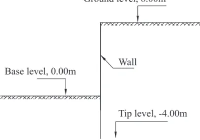
Ground level, 8.00m
Base level, 0.00m Wall
[image:3.595.309.557.49.261.2]Tip level, -4.00m
Figure 1: Rankine analysis geometry
Table 1: Soil parameters
Unit weight,γ 18 kN/m3 Cohesion intercept,c 0 kPa Angle of friction,φ 30◦
the soil and the retaining wall. The geometry for the basic analysis is shown in Figure 1 and the soil pa-rameters given in Table 1 have been used. A sliding only failure can be modelled in LimitState:GEO by setting Model rotations to be false.
Using the Rankine earth pressure coefficients (Eqs. 1, 2), the pressures acting on the active (Ka) and passive (Kp) sides of the wall can be calculated.
Ka= 1−sinφ
1 + sinφ (1)
Kp = 1 + sinφ
1−sinφ (2)
The active force is given by Pa = 0.5H2γKa where H is the total height of the retaining wall from crest to tip. The passive force is similarly given by Pp =
0.5H2γKp. By examining horizontal equilibrium, the
[image:3.595.57.257.52.192.2]required depth below the base of the wall to the tip (dw) can be calculated, which for the geometry in Figure 1 is 4.0m. To show that the DLO method can calculate the same mechanism and critical depth, the problem was set up in LimitState:GEO with the ge-ometry as specified in Figure 1. In LimitState:GEO the sheet pile wall is defined as an engineered
ele-ment (LimitState 2009) with an infinite moele-ment
re-sistance to match the rigid sheet pile modelled in the Rankine analysis. The wall must also have an infinite lateral capacity,N, so that the DLO method treats the wall as an impenetrable barrier as far as the soil is concerned. The interface between the retaining wall and the soil can be defined within LimitState:GEO by adding a second material to the wall. In this case, as a smooth interface is assumed, the second material is set withφ = 0to remove frictional effects.
Figure 2 shows the failure mechanism obtained us-ing LimitState:GEO. To find a collapse mechanism
[image:3.595.304.531.307.376.2]Figure 2: DLO failure mechanism
Table 2: Variation of adequacy factor with nodal density Nodal density No. of nodes Adequacy factor Course 250 1.012072156 Medium 500 1.003030377 Fine 1000 1.001162663 Custom 3000* 1.000544063 *User defined
an ‘adequacy factor’ must be applied to a force or self weight in the system to precipitate failure. For this scenario, adequacy was applied to the retained soil weight, and was found to be 1.001162663 for a ‘Fine’ nodal density. The adequacy factor is dependent on the nodal density of the analysis, and for an increasing number of nodes (which provide the end-points of po-tential lines of discontinuity) the adequacy factor will converge towards the analytical solution of 1.0. This is shown in Table 2.
By modelling the sheet pile wall as a rigid mate-rial the stress distribution around the wall can be
[image:3.595.306.559.573.754.2]ted. In a conventional sliding analysis active and pas-sive earth pressures are assumed to vary linearly with depth. However this is not a strict requirement in plas-tic limit analysis. Only the resultant of the stress dis-tributions must be the same. The DLO method with-out model rotations only examines horizontal and ver-tical equilibrium and generates a mechanism involv-ing a sinvolv-ingle wedge either side of the wall. This does not necessarily require a linear variation of pressure with depth. However if the wall is allowed to rotate, and fail in the expected mode for a cantilever wall, then the soil must also yield throughout the adjacent ‘wedges’ and the pressure distribution becomes well-defined. A linear variation with depth above the point of rotation is then predicted, as shown in Figure 3.
3.2 Rotational and bending failure
[image:4.595.306.540.45.249.2]The previous section has shown that the DLO method is capable of accurately analysing a sheet pile retain-ing wall for failure against slidretain-ing. In this section more complex modelling is undertaken with the in-clusion of both rotational failure mechanisms, a water table and yielding of the sheet pile wall. The DLO solutions have then been compared with results ob-tained using a lower bound finite element limit anal-ysis (FELA) method (Krabbenhoft et al. 2005). The problem geometry is defined in Figure 4, with the depth to the wall tip varying depending upon the sup-port conditions and friction on the soil-wall interface.
[image:4.595.306.550.297.513.2]Figure 4: Problem geometry, Krabbenhoft et al. (2005)
Table 3: Cantilever pile wall parameters Plastic moment resistance,Mp 982 kNm/m Tip level,dw -9.6 m Angle of wall friction,φ 0◦
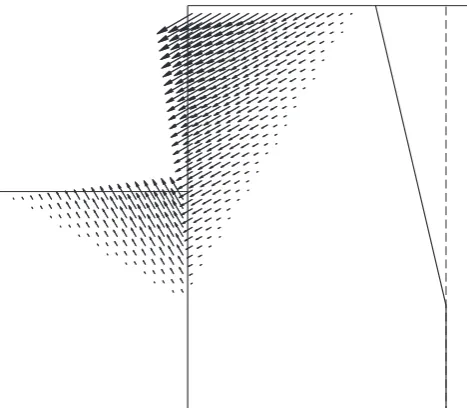
Figure 5 shows soil displacement vectors generated by the FELA method (Krabbenhoft et al. 2005) for the cantilevered sheet pile wall with no anchor. The soil and wall parameters are given in Tables 1 & 3. Specifying this problem in LimitState:GEO was done as for the sliding analysis but with the addition of
Figure 5: FELA vector plot for a smooth cantilever wall, Krabbenhoft et al. (2005)
Figure 6: DLO failure mechanism for a smooth cantilever wall
vertices being placed on the sheet pile wall around the expected point of yield (from Figure 5). Limit-State:GEO 2.0 is able to model rotations at vertices. By manually adding vertices the sheet pile wall is al-lowed to yield and bend at these locations. Figure 6 shows the failure mechanism predicted by the DLO method, indicating that the sheet pile wall yields at the same depth as predicted by the FELA analysis (Krabbenhoft et al. 2005). As the DLO method com-putes upper bound solutions, it would be expected to give a higher predicted factor of safety than a lower bound limit analysis method. Factor of safety is nor-mally defined on soil strength rather than self weight for retaining walls, thus partial factors are applied to
[image:4.595.40.275.444.588.2] [image:4.595.28.240.652.692.2]bound FELA analysis result given in Krabbenhoft et al. (2005). The true solution will lie somewhere be-tween the two results.
4 ANCHORED WALL ANALYSIS
The previous examples have looked at embedded can-tilever sheet pile walls where the failure mechanism involves a combined failure of the sheet pile and sur-rounding soil. To reduce the required embedded depth and required moment resistance of the pile, ground anchors can be used to help stabilize the retaining wall. The location of the anchor is given in Figure 4, being 1m down from the crest of the wall. Generally ground anchors can be modelled in two distinct ways:
• by an equivalent prop force acting on the face of the wall or,
• as a discrete soil reinforcement element.
Both approaches can be specified within Limit-State:GEO but to correctly assess the interaction be-tween the ground anchor and the failure mechanism the anchor should be modelled as a discrete soil rein-forcement element.
4.1 Anchor capacity
If the anchor is located too close to the wall, then the failure mechanism directly affects the pull-out resis-tance of the soil reinforcement element as the slip sur-face may cut through the position of the anchor. In this situation the capacity of the anchor is reduced to that equal to only the embedded end, thus giving a real-istic failure mechanism. The pull-out capacity of the anchorT can be assumed to vary proportionally with the vertical effective stress:
T =α(c+σv tanφmob)a (3)
where α = interaction coefficient;c = drained cohe-sion intercept;σv = vertical effective stress; andφmob
= mobilized angle of friction between the anchor and soil mass. For essentially 1D reinforcement such as soil nails, a=nπD where D is the diameter of the soil nail, and n is the number of soil nails per unit width.
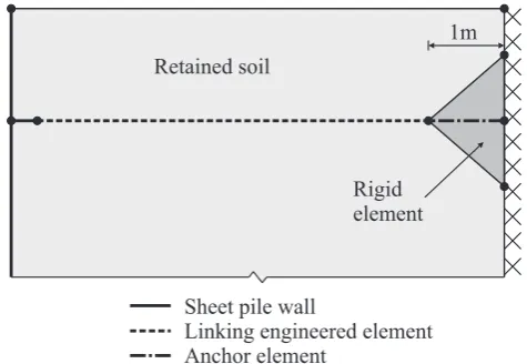
In certain situations the capacity of the anchor per metre length is unknown, but an ultimate pull-out resistance for a given anchor is known. This hap-pens most frequently when benchmarking the DLO method against work done by other authors, where the exact location of the generated slip surface is un-known (Krabbenhoft et al. 2005). Modelling a sin-gle, ultimate, pull-out resistance in LimitState:GEO which is independent of the failure mechanism can be achieved in several ways. Here it will be implemented by using an engineered element to tie the sheet pile to
1m
Rigid element Retainedsoil
Sheet pile wall
[image:5.595.314.552.45.209.2]Linking engineeredelement Anchorelement
Figure 7: Specifying an ultimate anchor capacity in Limit-State:GEO
an anchor at the boundary of the model, as shown in Figure 7.
There are three key components to this implemen-tation in LimitState:GEO, which are:
• the requirements of the linking engineered ele-ment,
• the interface between the sheet pile wall and linking engineered element and
• the specification of the anchor element.
The linking engineered element (LEE) is required to attach the sheet pile wall to the anchor that pro-vides the pull-out resistance. To have no impact on the failure mechanism the LEE must have zero bending moment, lateral and pull-out resistances, thus solely acting as a inextensible tie (or debonded tendon) be-tween the sheet pile wall and the anchor.
Figure 7 shows that the point at which the linking engineered element attaches to the sheet pile wall is not located directly on the wall. If the LEE (with a bending moment resistance of zero) is attached di-rectly to the sheet pile wall then this results in Limit-State:GEO modelling a zero-bending moment also at this point in the sheet pile wall. By attaching the LEE to an extended section of sheet pile wall this problem is eliminated.
Finally the capacity of the tie-back system is de-fined by the pull-out resistance of the anchor element within the rigid zone on the boundary, as seen at the right of Figure 7. This anchor element is modelled as a distinct engineered element with a specified pull-out capacityT. The anchor capacity is thus1×T.
4.2 Failure mechanism independent analysis
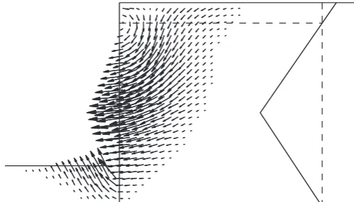
Figure 8: FELA vector plot for a rough anchored wall, Krabbenhoft et al. (2005)
Table 4: Anchored wall parameters
Plastic moment resistance,Mp 115 kNm/m Tip level,dw -2.0 m Angle of wall friction,φ 30◦ Anchor force,T 112 kN
[image:6.595.306.563.343.508.2]embedded depth to 2 m and the required moment re-sistance to 115 kNm/m. This analysis was done to mo-bilize full soil friction on the pile. The problem was set up in LimitState:GEO using the geometry given in Figure 4 and the soil and wall parameters given in Table 4. As was the case for the cantilevered wall, the factor of safety is defined in terms of a partial factor on soil strength. For an adequacy factor of 1, a par-tial factor of 1.032 was required, showing that the dif-ference between the lower and upper bound methods is 3.2%. From a comparsion between the vector plot and failure mechanism, it can be seen that the mode of failure is the very similar in both models.
Figure 9: DLO failure mechanism for a rough anchored wall
4.3 Failure mechanism dependent analysis
One of the main strengths of the DLO method is its ability to evaluate the stability of geotechnical prob-lems of any geometry, always finding the lowest
en-ergy solution. The anchored retaining wall analysis in the last section showed that DLO method is capable of closely matching the failure mechanism and factor of safety obtained using a lower bound FELA anal-ysis of a problem involving an anchor whose capac-ity is independent of the failure mechanism. As cussed earlier, the DLO method can also model dis-crete reinforcement, modelling the interaction of an anchor with the surrounding soil. An example of this is shown in Figure 10 where the LEE was replaced by an engineered element with a capacityT of 20 kN/m along its full length, and the single anchor adjacent to the boundary was removed. Now the factor of safety becomes a function of the length of the anchor and its influence on the failure mechanism. The parameters for the sheet pile wall remain unchanged from those given in Table 4. The analysis indicated that an anchor length of 11.45m was required to ensure wall stability. By comparing Figures 9 & 10 the effect of the discrete anchor on the failure mechanism can clearly be seen, with the failure mechanism in Figure 10 at-tempting to circumnavigate the anchor.
Figure 10: DLO failure mechanism for a rough anchored wall with a discrete anchor
5 CONCLUSIONS
This paper has demonstrated that the discontinuity layout optimization (DLO) procedure can be used to model sheet pile walls, and also, using a variety of methods, connected ground anchors.
[image:6.595.28.288.498.690.2]in the LimitState:GEO software, allowing rapid anal-ysis of retaining wall problems (run times were de-pendent on the nodal density specified, ranging from seconds to minutes on a modern desktop PC).
REFERENCES
Krabbenhoft, K., Damkilde, L. & Krabbenhoft, S. (2005). Ultimate limit state design of sheet pile walls by fi-nite elements and nonlinear programming,
Comput-ers and Structures 83 pp. 383–393.
LimitState (2009). LimitState:GEO Manual VERSION 2.0, sept 3 edn, LimitState Ltd.
Lysmer, J. (1970). Limit analysis of plane problems in soil mechanics, Journal of the Soil Mechanics and
Foun-dations Division ASCE 96 , 4: 1311–1334.
Makrodimopoulos, A. & Martin, C. (2006). Lower bound limit analysis of cohesive-frictional materials using second-order cone programming, Int. J. Num. Meth.
in Eng. 6 , 4: 604–634.
Sloan, S. (1988). Lower bound limit analysis using finite elements and linear programming, Int. J. Num. Anal.
Meth. in Geomech. 12 , 4: 61–77.
Smith, C. & Gilbert, M. (2008). Limit analysis of the sta-bility of foundations on inclined ground, 2nd BGA
International Conference on Foundations, Dundee,
pp. 1683–1692.
Smith, C. C. & Gilbert, M. (2007a). Application of discon-tinuity layout optimization to plane plasticity prob-lems, Proceedings of the Royal Society A:
Mathemat-ical, Physical and Engineering Sciences 463, 2086
pp. 2461–2484.
Smith, C. C. & Gilbert, M. (2007b). New upper bound solutions for layered soil bearing capacity problems using discontinuity layout optimization, 10th