This is a repository copy of Developing a hardware in-the-loop simulator for a backpack
energy harvester.
White Rose Research Online URL for this paper:
http://eprints.whiterose.ac.uk/81880/
Version: Accepted Version
Article:
Papatheou, E. and Sims, N.D. (2012) Developing a hardware in-the-loop simulator for a
backpack energy harvester. Journal of Intelligent Material Systems and Structures , 23 (7).
pp. 827-835. ISSN 1045-389X
https://doi.org/10.1177/1045389X12437886
[email protected] Reuse
Unless indicated otherwise, fulltext items are protected by copyright with all rights reserved. The copyright exception in section 29 of the Copyright, Designs and Patents Act 1988 allows the making of a single copy solely for the purpose of non-commercial research or private study within the limits of fair dealing. The publisher or other rights-holder may allow further reproduction and re-use of this version - refer to the White Rose Research Online record for this item. Where records identify the publisher as the copyright holder, users can verify any specific terms of use on the publisher’s website.
Takedown
If you consider content in White Rose Research Online to be in breach of UK law, please notify us by
Developing a hardware in-the-loop simulator for a
backpack energy harvester
E. Papatheou and N. D. Sims
Dynamics Research Group, Department of Mechanical Engineering, University of Sheffield, Mappin Street, S1 3JD, United Kingdom
e-mail: [email protected], [email protected]
Abstract
Energy harvesting from ambient sources has been the subject of several studies. Some of the proposed approaches attempt to generate electrical energy from the human movement. However, many of them can be uncomfortable or they impose a significant burden on the person’s gait. In the current paper the design of a hardware in-the-loop simulator for an energy harvesting backpack is presented. The idea is based on the energy produced by a suspended-load which moves vertically on a backpack while a person walks. The energy created from such a linear system can be maximised when it resonates with the walking frequency of the person. However, such a configuration can also cause great forces to be applied on the back of the user. The system which is proposed here consists of a mass attached on a rucksack, which is controlled by a motor in order to simulate the suspended-load backpack. The advantage of this setup is the ability to test different settings, regarding the spring stiffness or the damping coefficient, of the backpack harvester, and study their effect on the energy harvesting potential, as well as on the human gait. The present contribution describes the design, analysis, and preliminary testing of the hardware in-the-loop backpack system.
INTRODUCTION
The demand for smaller electronic devices is becoming higher over the past years. The techno-logical advancement has also resulted in such devices being able to consume significant amounts of power, something which poses several limitations in their use. Batteries which are frequently used in these situations, need to be recharged and they can also increase significantly the weight of the devices. Energy harvesting from ambient sources has appeared as a potential solution to the problem of the increasing demand for power in mobile electronic devices. The advantages gained from energy harvesting systems can also be easily applied in multidisciplinary areas. Many of the approaches which have been proposed attempt to exploit solar, thermal and kinetic energy sources among others. A review of power harvesting from vibration using piezoelectric materials can be found in (Sodano, Inman, and Park, 2004). Several other works have studied the potential of microelectromechanical systems (MEMS) for energy harvesting like (Stephen, 2006), and many of the approaches include linear as well as non-linear devices (Mann and Sims, 2009).
by Rome et al. (2005) with the use of a suspended-load backpack. The authors attached a mass on a rucksack which was hanged by springs and which was able to move vertically while the person who is carrying it walks. The load was connected through a gear and pinion to a motor and thus produced electrical energy.
A suspended-load backpack appears as an attractive solution for energy harvesting problems especially if it is considered for people who are already carrying a heavy backpack. In addition, several studies have investigated the influence of such a backpack on the human gait, something which is vital in any attempt to harvest energy through human movement. Rome, Flynn, and Yoo (2006) claim that using rubber bands to hang loads in a backpack reduces the metabolic cost. Xu, Hsiang, and Mirka (2009) observed some similar results by measuring the reaction forces produced by walking with suspended-load backpacks on a treadmill. Kuo (2005) has also made similar claims. The basic conclusions from those previous studies are that the phase difference between the movement of the torso and the movement of the load, influences the biomechanics of the human gait and this should be further investigated.
This paper presents the design of a hardware in-the-loop simulator of a suspended-load backpack. The main advantage of such a system is that different settings, regarding the spring stiffness and damping coefficient of the backpack, can be tested in order to optimise the energy dissipation (and hence the energy harvested), while aiming to improve the metabolic cost, and the comfort of the payload. In addition, the characteristics of the backpack can be adaptively changed since they are electrically synthesised.
The layout of the paper is as follows: the next section describes the theoretical model of a suspended-load backpack energy harvester. In the same section two simple numerical studies are also presented. The third section is concerned with the design of the actual backpack and also describes the modelling of the hardware in-the-loop system. In the same section the performance of the system is shown compared to a theoretical SDOF spring-mass-damper. The final section discusses the overall energy harvesting potential of the backpack and describes the further work which is planned to be carried out in order to study the effect of the suspended-load backpack on the human gait.
THEORETICAL MODEL OF A BACKPACK ENERGY HARVESTER
SDOF Model of a Spring-Mass-Damper
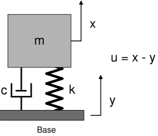
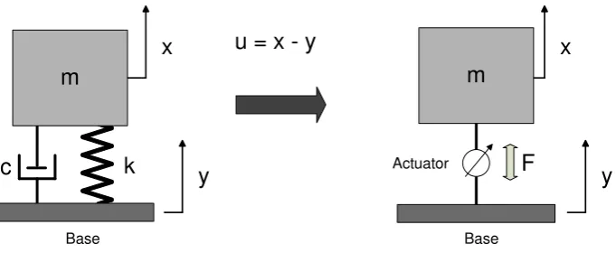
A suspended load-backpack consists of a load which is free to move vertically on the back of a rucksack while the person who carries the system walks. Figure 1 shows the simple model of a spring-mass-damper system under base excitation. This model represents closely the real suspended-load backpack system. The equations of motion from such a system can be found in any vibration textbook, e.g. (Rao, 2005),
mx¨+c( ˙x−y˙) +k(x−y) = 0 (1)
If we assume a sinusoidal excitation of the base in the form of,
y(t) =Y sin(ωt) (2)
then equation (1) becomes,
mx¨+cx˙+kx=ky+cy˙=kY sin(ωt) +cωY cos(ωt) =Asin(ωt−α) (3)
where A = Y√k2
+ (cω)2
and α = tan−1[−cω
k ]. The system is therefore equivalent to the
application of a harmonic force (of magnitudeA) to the mass. Again from (Rao, 2005) we can
find that the steady-state solution of the displacement of the mass can be written as,
k
c
y
x
Base
[image:4.595.238.397.60.196.2]u = x - y
m
Figure 1: Model of a SDOF spring-mass-damper system with a base excitation.
whereX and φcan be given by,
X Y =
[ k2
+ (cω)2
(k−mω2)2+ (cω)2
]1/2
=
[
1 + (2ζr)2
(1−r2)2+ (2ζr)2
]1/2
(5)
and
φ= tan−1
[
mcω3
k(k−mω2) + (ωc)2
]
= tan−1
[
2ζr3
1 + (4ζ2−1)r2
]
(6)
wherer = ωω
n is the frequency ratio and ζ is the damping ratio of the system. Equation (5) is
called displacement transmissibility. In a similar way the force transmitted to the base can be shown (Rao, 2005) to be,
F kY =r
2
[
1 + (2ζr)2
(1−r2)2+ (2ζr)2
]1/2
(7)
If the response of the mass relative to the base is required (u=x−y), then equation (1) becomes,
mu¨+cu˙+kr=−my¨ ⇒ u(t) =U sin(ωt−φ1) (8)
whereU and φ1 are given by,
U =Y r
2
√
(1−r2)2+ (2ζr)2
φ1 = tan−
1
( cω k−mω2
)
= tan−1
(
2ζr
1−r2
)
(9)
If the suspended-load backpack is modelled by such a SDOF spring-mass-damper system, then the theoretical maximum energy which could be potentially harvested by the vertical motion, can be calculated by the energy dissipated by the viscous damper. In practice, this implies that all of the dissipated kinetic energy is stored as electrical energy. The energy which is dissipated per cycle in a SDOF spring-mass-damper system with viscous damping can be given by (Rao, 2005),
∆W =πcωX2 (10)
where X is the amplitude of the steady-state solution of the displacement of the mass. In
It should be noted however that the energy calculated by equation (10) represents the max-imum possible value and it will be higher than the actual energy which would be harvested by any real system. Mechanical losses (e.g. friction) and electrical losses (e.g. power conversion and storage) will play a role. Nevertheless, equation (10) provides a good estimate for theoretical calculations. The power which is dissipated can be simply derived by multiplying the energy
per cycle with the frequency: ∆W ·f, wheref is the frequency in Hz.
Numerical Case Studies with Different Natural Frequencies of the Backpack
In order to maximise the energy production from a suspended-load backpack, the movement of the hanging mass should resonate with the walking frequency of the user. The resonance of the moving load will probably cause high reaction forces on the back of the person who is carrying the backpack. Two numerical case studies are shown here in order to highlight and demonstrate the effect of the stiffness and the damping on the theoretical production of energy and the reaction forces.
Natural Frequency of the Backpack near the Walking Frequency
A suspended load with a total mass of 10 kg is assumed to be hanged by a spring of stiffness
k = 1600N/m and a viscous damper with damping coefficient c = 40N s/m. The natural
frequency of this system is fn = 1
2π √
k
m = 2.01 Hz. The frequency of pedestrian walking may
depend on different factors, however in (Venuti and Bruno, 2009) mean values between 1.84 and 2 Hz are shown to be the findings of several authors. For the simple numerical case here
fh = 2 Hzwill be assumed as the typical frequency of the human gait. If a sinusoidal excitation
of the backpack frame is assumed to have an amplitude of Y=0.02 m, then by using equations (7) and (10) the total force transmitted and the power which is dissipated can be calculated. The force which would be applied on the wearer if the load was not moving at all, can be simply
calculated by using the absolute acceleration of the frame ¨y.
Natural Frequency of the Backpack smaller than the Walking Frequency
A second case is also shown here wherethe suspended load is assumed to have a similar
weight of 10 kg, but the spring stiffness is reduced to k = 600N/m. The damping coefficient
is left unchanged to the value of c = 40N s/m. The natural frequency of this system is now
fn = 1.23 Hz which is lower than the assumed walking frequency of the average person (2 Hz).
Again, a sinusoidal excitation of the backpack frame is assumed. By using equations (7) and (10) again, the power dissipated and the force which is transmitted can be derived.
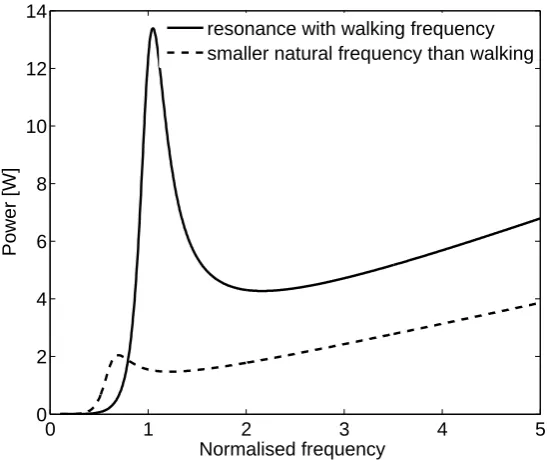
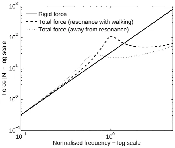
Figures 2 and 3 display the power which is dissipated plotted against the normalised
fre-quency f/fh, where fh is the assumed typical walking frequency and the force which is
transmitted to the backpack frame (and the user of the device). It can be seen that a suspended-load backpack with a natural frequency close to the human walking frequency resonates, and is able to harvest a significant amount of power. However, the force which is also transmitted to the user (see Figure 3) rises significantly near the area of resonance and is a lot higher than the force which would be transmitted if the load was fixed (conventional backpack). The latter force is depicted as “rigid force” in Figure 3.
When the natural frequency of the suspended load is lower than the assumed
human walking frequency of 2 Hz, the power dissipated has a peak around its resonance
again, but this time it happens around the value of 0.6 in the normalised frequency
of figure 2 (which corresponds to the resonance of 1.23 Hz). The energy produced
near the normalised frequency of 1 (when f = fh = 2Hz) is eight times smaller than
0 1 2 3 4 5 0
2 4 6 8 10 12 14
Normalised frequency
Power [W]
[image:6.595.157.431.55.285.2]resonance with walking frequency smaller natural frequency than walking
Figure 2: Power dissipation when the natural frequency of the suspended-load resonates and
when it is smaller thanthe walking frequency.
backpack in the area of 2 Hz (f/fh =1) is a lot smaller than the “rigid force” (the force of
a conventional backpack), which theoretically could make the process of carrying a backpack easier. The same effect is shown to be happening when the walking frequency increases. These results seem to be in some agreement with findings from Rome, Flynn, and Yoo (2006), where it was concluded that the metabolic cost for carrying a suspended-load backpack is less than that of a conventional backpack. However, Kuo (2005) claims that the main reason for that is the phase difference between the movement of the torso and the load. Equation (9) shows that the phase can be controlled by the natural frequency and the damping ratio. These results imply that the comfort of the user of this device can be influenced by altering the properties of the backpack. Another conclusion which can be drawn here is that the amount of power harvested in such a linear system drops sharply away from the resonance area, something which has been repeated in various previous studies e.g. Stephen (2006).
HARDWARE-IN-THE-LOOP SIMULATION OF A SUSPENDED-LOAD BACKPACK
Design of the Backpack
The previous simple analysis has displayed the general behaviour of a linear suspended-load backpack energy harvester. The results shown in the previous section have also implied that the influence of a suspended-load backpack on the human gait should be considered in the designing of a similar energy harvester. However, it should be noted here, that the assumption of a sinusoidal excitation of the backpack frame is not entirely accurate. Human walking, although periodical, has a more complex form than that of a simple sine. The authors acknowledge that the accurate modelling of the human gait is not a trivial issue, neither is the effort to model human perception. Consequently, the authors believe that the emulation of a spring-mass-damper system is easier and it presents a practically affordable way to study the effect of an energy harvester on human gait.
10−1 100 10−1
100 101 102 103
Normalised frequency − log scale
Force [N] − log scale
Rigid force
[image:7.595.148.431.50.290.2]Total force (resonance with walking) Total force (away from resonance)
Figure 3: Force transmitted when the natural frequency of the suspended-load resonates and
when it is smaller than thewalking frequency.
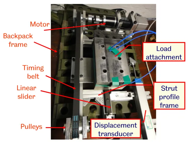
to control a mass to move vertically in the same way as it would move if it were attached by a spring and a damper of a specific stiffness and damping coefficient respectively. The system can easily be tested by humans to provide feedback on the perception of comfort and also to test the energy harvesting potential. A brushless Maxon DC motor was chosen for this task. The main drive mechanism consists of a timing belt which is able to convert the angular rotation of the motor to a translational movement of the mass. The mass will be able to move freely on a linear slider. A military backpack was purchased in order to be used as a frame for the whole system. Bosch Rexroth aluminium profiles were clamped on the military backpack in order to provide additional frame parts and mount the motor, the mass and the pulleys. Figure 4 shows a schematic of the system which was assembled. This schematic is only meant to aid the clarification of the drive mechanism. Figure 5 shows a photograph of the actual backpack system. All the main parts of the backpack can be seen in both figures (Figure 4 and Figure 5) including the motor, the timing belt, pulleys and linear slider.
Modelling of the Actual System
Figure 6 shows the diagram of the actual system (on the right) which is going to simulate the spring-mass-damper system (diagram shown on the left). If a free-body diagram of the mass is drawn in the ideal system then the following equation is derived,
ku+cu˙−mgcosθ=mx¨ (11)
whereu is the relative displacement with respect to the base of the mass, and ¨xis the absolute
acceleration of the mass. The angle θwill depend on the person who is carrying the backpack.
The actual system provides the following equation,
F−Fd−mgcosθ=mx¨ (12)
whereF is the force currently applied on the mass by the actuator andFdany disturbance force
(friction, sudden movement etc.). From equations (11) and (12) the following can be derived,
motor
m m
Shaft
Pulleys Belt
Frame
[image:8.595.156.440.83.300.2]Linear slider
Figure 4: Simple schematic of the backpack which is designed to simulate a spring-mass-damper system.
Backpack
frame
Linear
slider
Strut
profile
frame
Motor
Timing
belt
Pulleys
Load
attachment
Displacement
transducer
[image:8.595.136.454.434.674.2]k
c
y
x
Base
u = x - y
x
Base Actuator
y
F
[image:9.595.134.475.55.195.2]m
m
Figure 6: Model of the spring-mass-damper (idealised system on the left) which will be simulated by the actual system (on the right).
[image:9.595.107.488.254.374.2]Gc Km r c k Km -+ -+ - -+ R Ls 1 Km 1 Gr Rp J 1 s 1 Gf Z mass displacement Gr Rp Force Setpoint Current Setpoint Motor current I mass velocity Motor torque Motor speed Mechanical load s 1 + -m Gr Rp Force feedback Current regulation
Figure 7: Block diagram model of the hardware-in-the loop system.
whereFsis the set point force for the actual system. Equation (13) simply says that, in order to
control the mass such that the actual system simulates the ideal one, then the total force applied on the mass has to be controlled and remain always equal to the force of the ideal system. The easiest way to implement force control in the actual system, is to perform a current regulation on the motor. The current of the motor is directly proportional to the torque produced by it
through the motor constant (usually referred to asKm).
Figure 7 shows the block diagram of the hardware-in-the loop system which is meant to simulate the suspended-load backpack with the previously mentioned strategy of the current regulation. The motor can be modelled as an armature controlled DC motor with voltage as input and current, velocity (angular) or displacement (angular) as an output. The next step is the use of the mass displacement and velocity in order to calculate the total force which should be applied on the mass (according to the desired stiffness and damping values). The value of the total force can then be used as a setpoint to the motor (through current regulation). The following values are used in the block diagram of Figure 7: L is the motor inductance (it is usually so small that it can be neglected), R is the resistance, Km the motor constant, r is the friction term (on the motor rotation) and J contains all the mechanical load that the motor has to rotate. Gr is simply the reduction ratio of the gearbox used in the motor and Rp the pulley radius which is used to transform angular velocity to linear. The current regulation is noted on the block diagram as Gc and with Gf the force feedback controller is depicted. The force feedback was added to the block diagram in order to compensate for the extra inertia which is present on the system of Figure 7 in comparison to a simple spring-mass-damper.
PID
c k
--
-Mass displacement Force
Setpoint
Mass velocity Plant
DES 70/10
Force measured
xPC-target Desired values of
stiffness and damping
[image:10.595.100.493.52.174.2]+
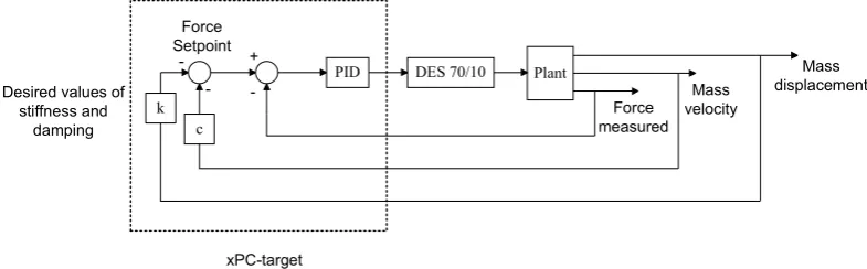
Figure 8: Block diagram of the control system which is realised in xPC-target.
was found identical. The controllers which were used were PID for Gc, and simple proportional for Gf. The gains of the controllers were chosen with the help of the root locus method. How-ever, the real challenge was to realise the same model in the actual backpack system. Several different strategies were available, but it was decided that the force feedback with the help of an accelerometer (on the mass) was the best with respect to the available budget,equipment and time. In order to produce the set point force the actual mass displacement and velocity is needed. Those values are obtained with the help of a linear displacement transducer (po-tentiometer) and with the use of the motor encoder for the measurement of the velocity of the mass.
Figure 8 shows a block diagram of the force regulation which is used in the actual system. The ‘plant’ subsystem represents the actual system of the motor with the pulleys along with the mass. The Maxon motor is controlled through a DES70/10 unit which is equipped with an integrated PI current regulation. The real-time control of the system is done with the help of xPC-target in MATLAB. With this strategy, the displacement and the velocity of the mass are constantly measured in order to produce the desired force setpoint which is then given as an input to the DES70/10 in order to perform current (torque) regulation. A standard PID controller was chosen to provide the closed loop control inside the real-time software (xPC-target) and its gains were initially chosen with the help of the root locus method. However, the assumptions which were made during the modelling stage (friction in the slider was not considered directly, backlash in the gearbox and pulleys) including the noise in the measurements of the mass displacement and velocity, led to the update of the PID gains. The main criterion for the final selection was the comparison of the FRFs of the backpack with that of a theoretical spring-mass-damper (which the backpack system attempts to simulate).
Comparison of the Performance of the Backpack System to that of a SDOF Spring-Mass-Damper.
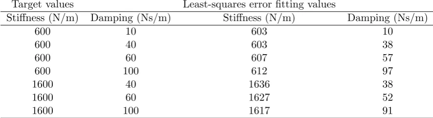
Figures 9 and 10 show the FRFs which were obtained by running the backpack under forced excitation in a frequency range of 0.5-3 Hz. The two cases of 1600 N/m and 600 N/m regarding the simulated stiffness, which were shown in the numerical section are also shown in Figures 9 and 10. The choice of the stiffness values was based on the same reasons as before, one case of resonance with the walking frequency, and one case of natural frequency smaller than the walking frequency. Figures 9 and 10 also show FRFs obtained with different damping coefficients. For
the case of 1600 N/m as stiffness three values of damping coefficient were tried,c= 40,60 and
100N s/m, which correspond to damping ratios of ζ = 0.159,0.238 and 0.397. For the case of
stiffness at 600 N/m, four values of damping coefficient were used,c= 10,40,60 and 100N s/m.
These values correspond to damping ratiosζ = 0.065,0.259 0.389 and 0.649.
Target values Least-squares error fitting values
Stiffness (N/m) Damping (Ns/m) Stiffness (N/m) Damping (Ns/m)
600 10 603 10
600 40 603 38
600 60 607 57
600 100 612 97
1600 40 1636 38
1600 60 1627 52
[image:11.595.77.520.46.167.2]1600 100 1617 91
Table 1: Stiffness and damping values obtained from curve fitting the measured FRFs.
a spring-mass-damper and although its response FRF is not identical to the theoretical, it can be considered adequate. Especially in the case of the stiffness value at 600 N/m, the backpack response is very close to the theoretical FRF, with the exception of the very low damping ratio case. If both the magnitude and the phase responses are combined then in the case of 600 N/m as stiffness, the resonance of the system has only a small difference of 1% from the theoretical. It is also clear that the system (backpack) struggles to simulate very low damping ratios and the reason for that may be the limitation of the force feedback strategy with the combination of hardware issues (friction on linear slider, motor response, backlash). Table 1 shows the results from fitting a SDOF model on the response FRFs (magnitude only) and clearly shows that the backpack performs much better in the stiffness value of 600 N/m (natural frequency lower than the walking frequency). Overall, the behaviour of the backpack is considered sufficient in order to simulate different settings to a satisfactory degree.
The forced response FRFs may be a good measure to check the performance of the system (and of the control gains), but it is not very close to the actual expected use of the mass. As was described in the second section of this paper, the base excitation system is the most accurate representation of the suspended-load backpack when its user is walking. In order to test the system under base excitation a hydraulic test rig was employed to shake the backpack as if it were being worn.
The backpack was tested under sinusoidal excitation in a frequency range of 0.2 - 4 Hz with different values of simulated stiffness and damping. Figures 11 and 12 show the trasnsmissibility
functions (U/Y, ‘mass displacement’/‘frame displacement’) in a frequency range of 0.5-3 Hz
for the two characteristic cases of stiffness at 1600 N/m (natural frequency in resonance with walking frequency) and 600 N/m (natural frequency below walking frequency). It can be seen again that the backpack performs much better when it simulates higher damping ratios in the case of 600 N/m as stiffness value. Again, the overall performance is considered adequate since the objective of this work is not to have the closest behaviour to the theoretical model, but close enough in order to be able to obtain useful conclusions regarding the energy harvesting potential of the system and its effect on the human gait. It should be said that the system was tested under sinusoidal excitation with different stiffness settings ranging from 100 N/m up to 2000 N/m and was found to behave adequately close to the theoretical (better in higher damping ratios and worse in lower).
0.5 1 1.5 2 2.5 3 0.2
0.4 0.6 0.8 1 1.2 1.4 1.6 1.8 2
2.2x 10
−3
Frequency [Hz]
Magnitude [m/N]
theory ζ = 0.159
theory ζ = 0.238
theory ζ = 0.397
backpack ζ=0.159
backpack ζ=0.238
backpack ζ=0.397
(a)
0.5 1 1.5 2 2.5 3
−180 −160 −140 −120 −100 −80 −60 −40 −20 0
Frequency [Hz]
Phase [
°
]
theory ζ = 0.159
theory ζ = 0.238
theory ζ = 0.397
backpack ζ = 0.159
backpack ζ = 0.238
backpack ζ = 0.397
[image:12.595.159.430.148.595.2](b)
0.5 1 1.5 2 2.5 3 0
0.002 0.004 0.006 0.008 0.01 0.012 0.014
Frequency [Hz]
Magnitude [m/N]
theory ζ = 0.065
theory ζ = 0.259
theory ζ = 0.389
theory ζ = 0.649
backpack ζ = 0.065
backpack ζ = 0.259
backpack ζ = 0.389
backpack ζ = 0.649
(a)
0.5 1 1.5 2 2.5 3
−180 −160 −140 −120 −100 −80 −60 −40 −20 0
Frequency [Hz]
Phase [
°
]
theory ζ = 0.065
theory ζ = 0.259
theory ζ = 0.389
theory ζ = 0.649
backpack ζ = 0.065
backpack ζ = 0.259
backpack ζ = 0.389
backpack ζ = 0.649
[image:13.595.156.428.149.595.2](b)
0.5 1 1.5 2 2.5 3 0
0.5 1 1.5 2 2.5 3 3.5 4
Frequency [Hz]
Transmissibility [U / Y]
theory ζ = 0.159
backpack ζ = 0.159
theory ζ = 0.238
backpack ζ = 0.238
theory ζ = 0.397
backpack ζ = 0.397
(a)
0.5 1 1.5 2 2.5 3
−180 −160 −140 −120 −100 −80 −60 −40 −20 0 20
Frequency [Hz]
Phase [
°
]
theory ζ = 0.159
backpack ζ = 0.159
theory ζ = 0.238
backpack ζ = 0.238
theory ζ = 0.397
backpack ζ = 0.397
[image:14.595.163.424.147.586.2](b)
Figure 11: Transmissibility (U/Y) of the theoretical spring-mass-damper and of the backpack
0.5 1 1.5 2 2.5 3 0
0.2 0.4 0.6 0.8 1 1.2 1.4 1.6 1.8 2
Frequency [Hz]
Transmissibility Magnitude
theory ζ = 0.259
backpack ζ = 0.259
theory ζ = 0.389
backpack ζ = 0.389
theory ζ = 0.649
backpack ζ = 0.649
(a)
0.5 1 1.5 2 2.5 3
−180 −160 −140 −120 −100 −80 −60 −40 −20 0 20
Frequency [Hz]
Phase [
°
]
theory ζ = 0.259
backpack ζ = 0.259
theory ζ = 0.389
backpack ζ = 0.389
theory ζ = 0.649
backpack ζ = 0.649
[image:15.595.161.426.145.584.2](b)
Figure 12: Transmissibility (U/Y) of the theoretical spring-mass-damper and of the backpack
comparison with the theoretical SDOF model being simulated, and this has been shown to be adequate for the purposes of this work.
CONCLUSIONS AND FURTHER WORK
This paper presented the design and the development of a prototype hardware in-the-loop sim-ulator for an energy harvesting backpack. The motivation for this work is drawn from previous conclusions regarding a suspended-load backpack, its energy harvesting potential and its effect on the human gait. The system built and presented here is not optimised for energy harvesting (significant mechanical losses are expected) and it is not currently used for energy harvesting. At this stage, it is only meant to simulate the behaviour of a similar energy harvesting system. After the testing of the system under sinusoidal excitation with help of a hydraulic shaker and the comparison of its behaviour to that of a SDOF spring-mass-damper, it can be concluded that it is possible to create a hardware in-the-loop simulator of a suspended-load backpack. In addition, the backpack can be definitely used to produce electrical energy from walking either through the use of the motor or through another power convertor (e.g. piezoelectric materials). The important point in the design of this system is that it can be smart and adaptive since it electrically synthesises the stiffness and the damping of the suspended load. The ability of the backpack to simulate different stiffness and damping settings also paves the way for future testing where the backpack is used to quantify the influence of these parameters on human sub-jects. The improvement of the design in order to minimise mechanical losses is also planned for further work.
ACKNOWLEDGMENTS
The support of the UK Engineering and Physical Sciences Research Council (EPSRC) and the Defence Science and Technology Laboratory (DSTL) through grant reference number EP/H020764/1 is gratefully acknowledged. The authors would also like to thank Mr Les Morton and Mr Chris Grigson for their invaluable help during the design and the building stage of the backpack prototype.
References
Donelan, J.M., Li, Q., Naing, V., Hoffer, J.A., Weber, D.J., and Kuo, A.D., 2008. “Biome-chanical energy harvesting: Generating electricity during walking with minimal user effort.” Science, 319(5864):807–810.
Feenstra, J., Granstrom, J., and Sodano, H., 2008. “Energy harvesting through a backpack employing a mechanically amplified piezoelectric stack.” Mechanical Systems and Signal Processing, 22(3):721–734.
Granstrom, J., Feenstra, J., Sodano, H.A., and Farinholt, K., 2007. “Energy harvesting from a backpack instrumented with piezoelectric shoulder straps.” Smart Materials & Structures, 16:1810–1820.
Kuo, A.D., 2005. “Harvesting energy by improving the economy of human walking.” Science, 309(5741):1686–1687.
Mann, B.P. and Sims, N.D., 2009. “Energy harvesting from the nonlinear oscillations of magnetic levitation.” Journal of Sound and Vibration, 319(1-2):515–530.
Rome, L.C., Flynn, L., Goldman, E.M., and Yoo, T.D., 2005. “Generating electricity while walking with loads.” Science, 309(5741):1725–1728.
Rome, L.C., Flynn, L., and Yoo, T.D., 2006. “Biomechanics - Rubber bands reduce the cost of carrying loads.” Nature, 444(7122):1023–1024.
Sodano, H.A., Inman, D.J., and Park, G., 2004. “A Review of Power Harvesting from Vibration using Piezoelectric Materials.” The Shock and Vibration Digest, 36(3):197–205.
Starner, T., 1996. “Human-powered wearable computing.” Ibm Systems Journal, 35(3-4):618– 629.
Stephen, N.G., 2006. “On energy harvesting from ambient vibration.” Journal of Sound and Vibration, 293(1-2):409–425.
Venuti, F. and Bruno, L., 2009. “Crowd-structure interaction in lively footbridges under syn-chronous lateral excitation: A literature review.” Physics of Life Reviews, 6(3):176 – 206.