COMPARATIVE EVALUATION OF THE SHEAR BOND
STRENGTH
BETWEEN
REPAIR
COMPOSITE
RESIN
BONDED TO BILAYERED AND MONOLITHIC CERAMIC
RESTORATIONS – AN IN VITRO STUDY
Dissertation Submitted to
THE TAMILNADU Dr. M.G.R. MEDICAL UNIVERSITY
In partial fulfilment for the Degree of
MASTER OF DENTAL SURGERY
BRANCH I
ACKNOWLEDGEMENT
First and foremost, I would like to thank God Almighty for giving me
the strength, knowledge, ability and opportunity to undertake this research
study and to persevere and complete it satisfactorily. Without his blessings,
this achievement would not have been possible.
After an intensive period of seven months, today is the day: writing this
note of thanks is the finishing touch to my dissertation. It has been a period of
intense learning for me, not only in the scientific arena, but also on a personal
level. Writing this dissertation has had a big impact on me. I would like to
reflect on the people who supported and helped me so much throughout this
period.
I would like to express my sincere gratitude to Professor Dr. N.S. AZHAGARASAN M.D.S., Principal & Head, Department of
Prosthodontics and Crown & Bridge for the continuous support of my study & research, for his patience, motivation, enthusiasm and immense knowledge.
My sincere gratitude also goes to Professor Dr. K. Chitra Shankar M.D.S., whom I have come to admire and would love to follow her way of professionalism in the field of academics. Her encouragement, insightful
comments and hard questions always kept me on my toes to hunt for answers
and learn from it.
I have great pleasure in acknowledging my Guide,
guidance. He has given me all the freedom to purse my research, while silently
and non-obtrusively ensuring that I stay on course and do not deviate from the
core of my research.
I am also deeply thankful to my ProfessorDr. S. Jayakrishnakumar,
M.D.S., for his critics, doubts and questions in the field of my study, which always kept me on vigil and correct my mistakes and succeed in my research.
I would also like to thank Dr. M. Saravanakumar, M.D.S., Professor,
Dr. R. Hariharan, M.D.S., Reader for providing me their insights in my research topic, when I approached them with the methodology, which helped
me to proceed forward with the study.
I would like to extend my thanks to those who offered guidance and
support over the years: Dr. J. Vidhya, M.D.S., Reader Dr. Vallabh
Mahadevan, M.D.S., Reader Dr. Shameem, M.D.S., Dr. Manoj Kumar, M.D.S., Dr. Mahadevan, M.D.S., Dr. Kamatchi, M.D.S
I am so grateful to Mrs. Bhuvana & Mr. Aasai Thambi for helping me with their knowledge in the field of shear testing for my samples. I take this
opportunity to acknowledge and thank Central Institute of Plastic
Engineering and Technology, Chennai for providing me with necessary equipments for my study.
I would like to thank my good friend and well-wisher
DR. KHUSHBU SHARMA for helping me with all statistical works of my thesis.
I take this opportunity to thank Mr. K. Thavamani, Scribbles for helping me with all the printouts and binding of my months’ work into
presentable books.
There is nothing more valuable in life than finding a best friend as
Dr. A. UDHAYABANU KRISHNAN, M.B.B.S. Her friendship has helped me grow, kept me grounded, lifted my spirit, brightened my life and pulled me up
whenever I found myself at the bottom. I would love to thank her for her
friendship from my school days till now and in future too.
I would love to thank Dr. Abinaya Sekar, whom I found in my journey
towards this degree. She turned out to be the most valuable friend who put up
with all my mood swings, my mistakes, my failures and helped me to come out
successful.
My journey in this field of dentistry would not have begun without the
support of my parents Mr. J. DHAKSHINAMOORTHY and
Mrs. P. THARABAI DHAKSHINAMOORTHY. Am indebted to them throughout my life. Without their love and support I would not be able to stand
where I am now. They picked and dusted me up whenever I fell, encouraged
against me. Simple note of acknowledgement is not enough for the most
precious things they did to me. Am more than grateful for them.
In my heart and mind, I have been blessed with the good fortune of
having a brother Mr. DEVAKAR DHAKSHINAMOORTHY to be my side for
a lifetime. Though younger by birth he funded to all my thesis work. He
supported me when I couldn’t stand, believed in me in whatever I chose to do,
protected me from all the evils. The greatest gift our parents ever gave us was
each other.
Special thanks to my junior Dr. M. Asish who helped me with all the
photographs of my thesis work.
It would be inappropriate if I omit to mention the names of all my
seniors, juniors and my colleagues Dr. Syed Ershad Ahmed, Dr. Sherin
CONTENTS
S.NO
TITLE
PAGE NO.
1.
INTRODUCTION
01
2.
REVIEW OF LITERATURE
10
3.
MATERIALS AND METHODS
27
4.
RESULTS
44
5.
DISCUSSION
50
6.
CONCLUSION
63
7.
SUMMARY
65
ANNEXURE I
METHODOLOGY OVERVIEW
ANNEXURE II
LIST OF FIGURES
Fig. No TITLE
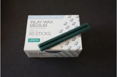
Fig. 1: Inlay wax
Fig. 2a: Sprue wax 3.5mm
Fig. 2b: Silicon cast ring
Fig. 2c: Crucible former
Fig. 2d: Aura film surfactant spray
Fig. 2e: Phosphate bonded investment material
Fig. 3: Aluminium oxide powder-50µm
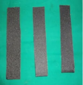
Fig. 4: Silicon carbide papers 220, 320 and 400 grits
Fig. 5: Trimming and polishing kit
Fig. 5a: Carborundum disc, tungsten carbide metal trimming burs, mandrel & silicon wheel
Fig. 5b: Diamond abrasive & white wheel
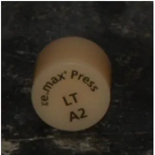
Fig. 6: Lithium disilicate monolithic ceramic (IPS emax press)
Fig. 8: 5% Hydrofluoric acid
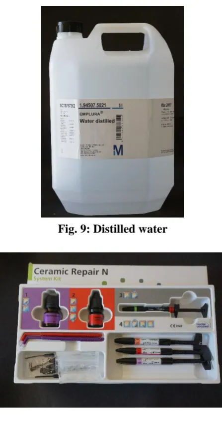
Fig. 9: Distilled water
Fig. 10: Repair composite (Ivoclar Vivadent Ceramic Repair N kit)
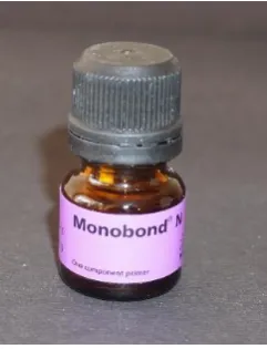
Fig. 11: Silane coupling agent (Monobond N)
Fig. 12: Bonding agent (Heliobond)Tetric N-ceram
Fig. 13: Repair composite resin (Tetric N-ceram)
Fig. 14: Acetate sheet
Fig. 15: Wax knife
Fig. 16: Wax carver
Fig. 17: Plastic instrument
Fig. 18: Vacuum mixer
Fig. 19: Burnout furnace
Fig. 20: Ceramic furnace
Fig. 21: Sandblasting machine
Fig. 22: Light curing unit
Fig. 23: Scanning Electron Microscope- Sputtering machine
Fig. 24: Scanning Electron Microscope
Fig. 25: Automated Thermocycling unit
Fig. 26: Universal testing machine
Fig. 27: Customized stainless steel jig
Fig. 27a: Main body
Fig. 27c: 2mm spacing disc
Fig. 27d: Wax flushing disc
Fig. 27e: Central defect rod
Fig. 27f: Locking screw
Fig. 27g: CAD diagram of jig
Fig. 28: Increment jig
Fig. 28a: 2mm
Fig. 28b: 1mm
Fig. 28c: CAD diagram of increment jig
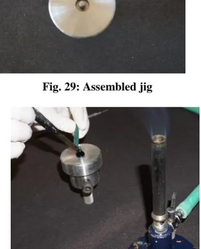
Fig. 29: Assembled jig
Fig. 30: Wax poured into mould space
Fig. 31: Flushing out excess wax
Fig. 32: Wax pattern
Fig. 33: Wax pattern (Group I)
Fig. 34: Wax pattern (Group II)
Fig. 35: Spruing of wax patterns
Fig. 36: Investing
Fig. 37: Burnout investment
Fig. 38: Ceramic pressed
Fig. 39: Divested ceramic samples
Fig. 40: Sprue removed
Fig. 42: Layering ceramic firing
Fig. 43: Completed bilayered lithium disilicate ceramic restoration (Group I)
Fig. 44 Spruing of wax patterns
Fig. 45 Investing
Fig. 46 Burnout procedure
Fig. 47 Ceramic Ingot heat press
Fig. 48 Divested ceramic samples
Fig. 49 Sprue removed
Fig. 50: Completed monolithic lithium disilicate ceramic restoration (Group II)
Fig. 51: 5% HF acid
Fig. 52: HF acid etching
Fig. 53: Distilled water rinsing
Fig. 54: Surface dried with oil free air spray
Fig. 55: Gold sputtering of etched test samples prior to SEM analysis
Fig. 56: SEM analysis of surface characteristics of etched surface
Fig. 57: Silane coupling agent
Fig. 58: Silanization of etched surface
Fig. 59: Bonding agent
Fig. 60: Application of bonding agent
Fig. 62: A2 shade repair composite
Fig. 63: Repair composite placed inside the increment jig
Fig. 64: Placing the measured composite increment in defect and condensing
Fig. 65: Light curing the composite increment
Fig. 66: Test samples stored in distilled water
Fig. 67: Thermocycling of the test samples
Fig. 68: Shear bond strength testing of test samples
Fig. 69: Gold sputtering of debonded test samples prior to SEM analysis
ANNEXURE III
SEM IMAGES OF ETCHED SURFACE TOPOGRAPHY
BEFORE REPAIR
IMAGE.
No.
TITLE
Fig. 71: SEM photomicrograph of representative etched surface of Group I test sample before repair composite resin filling under 2000X magnification
LIST OF TABLES
Table
No.
TITLE
Page
No.
I. Basic and mean shear bond strength (MPa) of repair composite resin bonded to bilayered lithium disilicate ceramic restorations (Group I)
47
II. Basic and mean shear bond strength (MPa) of repair composite resin bonded to monolithic lithium disilicate ceramic restorations (Group II)
48
III. Comparative evaluation of the mean shear bond strength between repair composite resin bonded to bilayered lithium disilicate ceramic restorations (Group I) and repair composite resin bonded to monolithic lithium disilicate ceramic restorations (Group II) using Mann-Whitney U non- parametric test
ANNEXURE IV
LIST OF GRAPHS
Graph.
No.
TITLE
I. Basic data of shear bond strength between repair composite resin bonded to bilayered lithium disilicate ceramic restoration (Group I)
II. Basic data of shear bond strength between repair composite resin bonded to monolithic lithium disilicate ceramic restoration (Group II)
ANNEXURE V
SEM IMAGES OF MODE OF FAILURE
IMAGE.
No.
TITLE
Fig. 73: SEM photomicrograph of representative test sample of Group I (bilayered lithium disilicate ceramic restoration) under 2000X magnification
1
INTRODUCTION
The ceramo-metal restoration has been the gold standard in crown & bridge procedures for several years. Although durable and time-tested, patient’s demand for metal-free restorations mainly for esthetic reasons, and the demand has been met with various all ceramic systems.
Traditionally, the ceramo-metal restoration is fabricated by casting a metal coping and subsequently applying layers of layering ceramic. Newer methods have bypassed the metal coping fabrication step. Using a vacuum-pressing system, all-ceramic restorations are waxed to full contour and invested, wax pattern is burnt out and hot-pressed, creating a solid ceramic restoration.
2
Once the cores are fabricated, the laboratory technician applies layering ceramics to create the final esthetic restoration. Core – layering interface is one of the weakest aspects of layered All – ceramic crowns. Many experiments were run in order to find a way to minimize cracking, chipping and fracture.23 Fracture resistance of all these indirect restorations decreases with the variety of oral conditions (temperature changes, chewing pressure, etc.) and usage time.1, 22 It was proved that the composition of the ceramics and different firing processes could influence mechanical, physical, and esthetic process.23
The evolution of glass-ceramics in the dental field was profoundly influenced by the increase in crystalline structure of upto 60-70% and reinforcement through lithium-disilicate. This led to a flexural strength two or three times higher than that of conventional glass-ceramics leading to a stability that made glass-ceramics suitable for restorations in the molar region. 23, 71
A cumulative survival rate of 94.8% after 8 years declare lithium disilicate crowns a reliable treatment option, no matter how far posterior the restoration was located in the dentulous jaw. Therefore lithium disilicate ceramic seems a promising material for dental restorations, even in the molar region.23
3
excellent esthetic results such as high translucency with good mechanical properties, doubts still remain concerning long-term durability. 23, 56, 71
The smallest of porosities in the glass-ceramic surface and micro-flaws allow penetration of fluids such as saliva and water which can promote the growth of cracks and spontaneous chipping, leading to a fracture of the restoration. 22, 23, 71 Unsupported glass ceramics – even those with high flexural strength are prone to fracture under chewing loads.46 Fracture of ceramic restorations lead to increased cost, discomfort, time and labour when a replacement is required. Because it is arduous to remove these restorations from the mouth, the ceramic restorations may be repaired intraorally.20, 21, 22,
Intraoral repair may help in lengthening the life span of the fractured restoration. Studies have shown the contact damage is induced at the loading, occlusal surface for molars and premolars or palatine surfaces for incisors. Wang et al88 showed that all ceramic restorations demonstrated a fracture rate of 4.4% at a 5-yr follow-up in a clinical study.22
4
Depending on the size of the cracks and/or fractures, the suitable treatment approach is chosen. In case of an anterior restoration or a restoration in the esthetic zone, repair or replacement procedure is inevitable. Minor chippings of the ceramic material especially in case of a multiunit restoration do not necessarily warrant for replacement of the entire restoration. Moreover, replacement leads to time consuming and expensive procedures. Removal of the restoration can be postponed or averted with intraoral repair. Because of the nature of the ceramic processing, new ceramics cannot be added to an existing restoration intraorally. Thus, intraoral repair can be considered as an emergency treatment for localized fractures.30, 43, 68
A number of ceramic repair materials and techniques are available to repair the fractured/chipped restorations. Different ceramic surface treatments have been introduced to improve resin bonding to ceramics. Repair composite restoration was a conservative method that can increase the longevity and durability of restorations while preserving the old restorations. This approach is conservative and cost effective because the intact part of the restoration remains untouched.4, 22, 23, 33, 41, 60, 71, 83
5
The imperfect restorations can be corrected by bonding resin composite to ceramic restorations to avoid or postponing the procedure of complete replacement of restoration. The procedures includes surface preparation of restoration and silane application and bonding agent.22, 74
Surface treatment on the fractured ceramic surface must be performed in the repair procedures. It involves mechanical and chemical treatments to create irregularities on the surface. Roughening with diamond burs, etching with hydrofluoric acid, sand blasting or embedding a ceramic layer surface (CoJet) are the some of the surface treatments recommended for ceramics.4, 20, 26, 30, 55
Duzyol et al 22 in his study suggested that hydrofluoric acid etching was the best lithium disilicate surface treatment and roughening with bur and sand blasting were not appropriate for lithium disilicate. Hydrofluoric acid (HF) removes the glass matrix and the second crystalline phase, thus creating irregularities within the lithium disilicate crystals for bonding.13, 24, 28, 73, 80
6
Adequate surface treatment for lithium disilicate glass ceramic was achieved with the HF concentration of 5% applied for 20 seconds.52, 65, 67, 71 The use of HF for intraoral repair procedures can also be dangerous to adjacent tissues, these techniques should be applied much more carefully than other techniques.85 This physical bond combines with the chemical bond obtained from the use of a silane agent to provide a high strength bond between the composite and ceramic.25
Clinical and laboratory data suggest that before bonding the resin composite to damaged ceramic, the surface should be treated with a silane coupling agent.22 Adhesive bonding depends on the surface energy and wettability of the adherent by the adhesives.27 The adhesion between resin-based composite and dental ceramics are the result of a physiochemical interaction across the interface between the adhesive and substrate.12, 27
7
Clinically, when ceramic restorations are cemented and exposed to the oral environment, factors that could result in fatigue may influence their physical and mechanical properties. Fatigue fracture is a form of failure that occurs in structures with microscopic cracks subjected to dynamic and fluctuating stresses.28
Continued loading during mastication results in stress concentration, whereas thermal variations induce fatigue, and these cracks propagate and weaken the restoration. Catastrophic fracture results from a final loading cycle that exceeds the loadbearing capacity of the remaining sound portion of the material. Thermal variations and the evaluation of fatigue resistance of dental ceramics could provide a more detailed understanding of clinical failures.28, 78
Numerous studies, evaluating the shear bond strength between repair composite and monolithic lithium disilicate ceramics are available in the literature. These studies had focused on different repair composite resins and/or different types of surface treatment agents, including different concentrations and duration as their study variables.22, 23, 28, 38, 64, 65
8
comparing the shear bond strength between the repair composite resin bonded to either bilayered or monolithic lithium disilicate ceramic are lacking.
Therefore, in view of the above, the aim of the present in vitro study was to comparatively evaluate the shear bond strength between repair composite resin bonded to bilayered and monolithic lithium disilicate ceramic restorations. The null hypothesis of the present study was that there will be no significant difference in the shear bond strength between the repair composite resin bonded to bilayered and monolithic lithium disilicate ceramic test groups.
The objectives of the present study were as follows:
1. To evaluate the shear bond strength of repair composite resin bonded to bilayered lithium disilicate ceramic restoration.
2. To evaluate the shear bond strength of repair composite resin bonded to monolithic lithium disilicate ceramic restoration.
9
4. To qualitatively analyse the surface topography of etched Group I and Group II representative test samples before repair composite resin filling. 5. To qualitatively analyse the mode of failure on the repair composite resin
surface bonded to bilayered lithium disilicate ceramic restoration by Scanning Electron Microscopy (SEM).
10
REVIEW OF LITERATURE
Wolf et al (1992)90 evaluated tensile bond strength of composite to porcelain using three pretreatments (HF etching, sandblasting, diamond abrasion), four bonding agents (Clearfil Porcelain Bond, Porcelain Liner M, Porcelain Liner M with Super-Bond C&B, and Scotchprime) and two storage conditions (24 h and thermocycling) under in vitro condition and found that thermocycling decreased the bond strength of all except the samples treated with Scotchprime being less affected.
Suliman et al (1993)83 evaluated porcelain repair with surface treatments air abrasion, roughening with a diamond, etching with 9.6% HF, and a combination of the latter two methods. Silane coupling agent was applied and composite resin was bonded to porcelain with All-Bond 2, Amalgambond or Clearfill Porcelain bonding agents. Shear bond strength was tested, for all test groups.
Thurmond et al (1994)85 evaluated the bond strength of composite resin bonded to porcelain surfaces under variety of treatment regimens with the All-Bond 2 adhesive system and found significant differences in the 24-hour bond strengths between several of the surface treatment methods.
11
condition on bond strength. The variables included three ceramics (Dicor8, Mirage', Vitabloc"), three surface-roughening methods (etching, sandblasting, grinding), three silane treatments (y methacryloxypropyltrimethoxysilane [MPS], MPS + paratoluidine, vinyltrichlorosilane), two heat treatments (20°C for 60 s, 100°C for 60 s), and two storage conditions (24-hour dry, one year in water at 37°C). Of the surface roughening methods, etching showed higher bond strength values than either sandblasting or grinding and water storage of etched ceramics remained constant in comparison with both sandblasted and ground specimens which were decreased by from 50 to 75% under dry storage.
12
Matsumura et al (1997)49 evaluated bond strengths of ceramic bonding materials in conjunction with their initiation and silane-activation modes. For this study a disk-shaped fired porcelain specimens were air-abraded with alumina, then bonded with six combinations of three silane priming and two luting agents and the specimens were also bonded with two luting cements without priming. Shear bond strengths were determined in both before and after thermocycling condition. The reduction in bond strengths after thermocycling was remarkable as compared with the corresponding pre thermocycling groups. They also concluded that for feldspathic porcelain restorations all the three systems appeared to be useful for the long-term clinical success.
13
after hydrofluoric acid etching appeared to be suitable for achieving consistent bonding between the composite resin and the porcelain.
Jardel et al (1999)36 evaluated the effect of surface modifications with hydrofluoric acid gel (concentration 10%) on the surface energy of 2 dental feldspathic ceramics (GC and PVS). They found that evolution of the work of adhesion depended on the action of the hydrofluoric acid gel on the roughness of the surface of the 2 ceramics. The ceramics etched with hydrofluoric acid gel increased the work of adhesion, especially for GC, but this treatment was not sufficient to obtain a high work of adhesion, hence silanization is preferable to etching.
14
Kato et al (2001)39 determined the bond strengths of adhesive resins joined to a feldspathic porcelain (VMK 68). For this study they considered three porcelain surfaces-ground, air-abraded with alumina, and etched with hydrofluoric acid. And for priming agent a two-liquid porcelain conditioner that contained both 4-methacryloyloxyethyl trimellitate anhydride and a silane coupler (Porcelain Liner M) was used. In order to examine the effects of the respective chemical ingredients on adhesive bonding each of the two liquid components of the conditioner was also used individually. As for the luting agents two methyl methacrylate based resins initiated with tri-n-butylborane either with or without 4-META were used. Shear bond strengths both before and after thermocycling were determined. And the results indicated that thermocycling was effective for disclosing poor bonding systems. Etching with hydrofluoric acid followed by two-liquid priming with the Porcelain Liner M material generated the most durable bond strength.
15
pores and precipitates on the surface and as the etching time increased these channels were replaced by larger channels and EDS analyses showed that the crystalline precipitates on the etched surfaces, which were not readily soluble in water were observed. And etching with HF displayed a more roughened surface than the APF gel. However, only by the ultrasonic cleaning the precipitates remain on the surface after acid application, they can only be removed.
Stewart et al (2002)82 evaluated immediate and 6-month shear bond strengths between a feldspathic ceramic and 4 different resin cements with the use of 6 different surface-conditioning treatments. Shear bond strengths between the resin cements and dentin also were measured. The specimens received 6 different surface conditioning treatments before the application of resin cement. These surface treatments were treated with 600-grit silicon carbide paper, microetching with aluminum oxide followed by silane application, microetching followed by silane application, hydrofluoric acid–etching, and hydrofluoric acid–etching followed by silane application. The results of the study showed hydrofluoric acid– etching followed by silane application produced the best bonds at 24 hours and 6 months with all 4 cements. Auto- and light-polymerized adhesives were associated with higher bond strengths to dentin than dual-polymerized adhesives.
Kussano et al (2003)44 evaluated the shear bond strength of
porcelain/composite using 40 metal + porcelain + composite cylindrical
16
treatment, 2) mechanical retentions performed with diamond burs, 3) etching with
phosphoric acid+silane, and 4) etching with hydrofluoric acid+silane. The
specimens were submitted to a shear force (load) after being stored in distilled
water at room temperature for one week and the data were analyzed statistically
and found no statistical significant difference between groups 1 and 2 and
between groups 3 & 4.
Borges et al (2003)13 assessed the surface topography of six different ceramics after treatment with either hydrofluoric acid etching or airborne aluminum oxide particle abrasion. Five copings each of IPS Empress, IPS Empress 2 (0.8 mm thick), Cergogold (0.7 mm thick), Ceram Alumina, In-Ceram Zirconia, and Procera (0.8 mm thick) were fabricated. Group treated with hydrofluoric acid etching and airborne particle abrasion with 50µm aluminum oxide increased the irregularities on the surface of IPS Empress, IPS Empress 2, and Cergogold ceramics. But the similar treatment of Ceram Alumina, In-Ceram Zirconia, and Procera did not change their morphologic microstructure.
17
Final results showed that the liquid resin medium yielded a lower WA than water and silanization produced a significantly lower WA than non-silanated surfaces, also etching alone consistently yielded a greater WA for all surface treatments.
Nagai et al (2005)52 evaluated the bonding characteristics of a lithium disilicate-based ceramic material (IPS Empress 2). surface-prepared using three techniques; etching with phosphoric acid, etching with hydrofluoric acid, and air-abrasion with alumina were considered as sample preparation. And the ceramic was bonded to Variolink II composite with and without Monobond- S silane primer, Super-Bond acrylic adhesive. And shear bond strengths were determined before and after 100000 thermocycles. Bond strength evaluated after silane primer application of both luting agents regardless of surface preparation method and concluded that for both luting agents, the durable bond to the Empress 2 ceramic material can be achieved through the combined application of HF and the proprietary silane primer.
18
polymerized onto the ceramic specimens. They concluded that the alumina and zirconia ceramic specimens treated with a silica coating technique, and lithium disilicate ceramic specimens treated with airborne-particle abrasion and acid etching yielded the highest tensile bond strength values to a composite resin for the materials tested.
Nagayassu et al (2006)53 evaluated the effect of different surface
treatments on the shear bond strength of a resin-based cement to porcelain.
Different surface treatments: etching with 10% hydrofluoric acid for 2 or 4min
(G1 and G2); 50-μm particle aluminum oxide sandblasting for 5 s (G3);
sandblasting followed by etching for 2 or 4min (G4 and G5) and control - no
treatment (G6) were employed. And silane agent was applied to the treated
surface of both discs of each pair. Later Bistite II DC dual-cure resin cement was
used for bonding both discs. They concluded that 2-min hydrofluoric acid etching
produced a favorable micromechanical retention that enhanced resin cement bond
strength to porcelain.
19
with 1.23% APF gel for 7 to 10 minutes were not significantly different than that after etching with 9.6% hydrofluoric acid for 4 minutes.
Panah et al (2008)62 evaluated the influence of different ceramic surface treatments on the micro-shear bond strength of composite resin to IPS Empress 2 coping material. 16 lithia disilicate based core ceramic plates were fabricated using the lost wax technique and the plates were divided into eight groups. Eight different surface treatments were performed which were as follows: (1) no treatment (NT); (2) airborne-particle abrasion with 50-μm alumina particles (Al); (3) acid etching with 9.6% hydrofluoric acid for 1 min (HF); (4) silane coating (S); (5) AlHF; (6) AlS; (7) HFS; and (8) AlHFS. They found that the micro-shear bond strength of a composite resin to IPS Empress 2 was significantly different depending on the surface treatment method. And among the investigated methods, silane coating after airborne-particle abrasion and etching was the most effective surface treatment in terms of bond strength increase were reported.
20
systems may not be indicated and if maximum bond strength is the goal in porcelain resin bonding, adhesive systems that have a high filler ratio should be used.
Ozcan et al (2009)60 compared the durability of repair bond strength of a resin composite to a reinforced ceramic after three repair systems. PR-Porcelain Repair Kit (Bisco), CJ-CoJet Repair Kit (M ESPE), CL-Clearfil Repair Kit. Specimens were tested either immediately after beam production (Dry) or after long-term water storage (37 ◦C, 150 days) followed by thermocyling. When tested in dry conditions, cohesive failure in the composite accompanied with adhesive failure at the interface (mixed failures), was frequently observed. After aging conditions, the specimens treated with PR and CJ presented primarily mixed failure type, CL group presented mainly complete adhesive failures at the interface
Fabianelli et al (2010)24 evaluated the effect of different surface treatments on the microtensile bond strength between a leucite reinforced glass– ceramic and composite resin. Surface treatments were: G1: hydrofluoric (HF) acid and silane; G2: silane alone; G3: HF acid and silane then dried with warm air (100º
21
adhesion between the ceramic restoration and the resin cement and enhancing the condensation reaction by drying the silane with a 100°C warm air stream significantly improved the microtensile bond strength, possibly eliminating the need for the hydrofluoric acid etching step.
Zogheib et al (2011)94 examined the effect of different acid etching times on the surface roughness and flexural strength of a lithium disilicate-based glass ceramic. Specimen were produced from ceramic blocks were polished and sonically cleaned in distilled water and were randomly divided into 5 groups as follows: Group A (control) no treatment. Groups B-E were etched with 4.9% hydrofluoric acid (HF) for 4 different etching periods: 20 s, 60 s, 90 s and 180 s, respectively. They concluded that the HF etching significantly reduced the mean flexural strength as the etching time increased.
Brum et al (2011)15 assessed bond strength between resins and ceramics. They have used surfaces that have been ground flat to ensure standardization. The groups were classified according to polished and unpolished surface and were treated with HF. They concluded that hydrofluoric acid provides the highest bond strength regardless of whether the surface is polished or not.
22
thermocycling. They concluded that the interfacial fracture toughness for the lithium disilicate glass ceramic system was affected by the surface treatment and the type of luting agent and dual-cured resin cements demonstrated a better bonding efficacy to the lithium disilicate glass ceramic compared to the self-adhesive resin cement.
Vidotti et al (2013)87 evaluated the influence of low concentration acid treatment on the shear bond strength between lithium disilicate (LD) infrastructure and veneering porcelain. Scanning Electron Microscopy (SEM) analysis showed no morphological differences between treated and untreated surfaces. Low concentration acid treatment did not improve SBS of veneering ceramic to LD and did not cause morphological changes on the LD surface.
23
Colares et al (2013)20 evaluated the influence of ceramic surface treatments and silane drying temperature on the microtensile bond strength (μTBS) of a resin composite to a lithium disilicate ceramic. They concluded that as far as the bond strength is concerned, surface pretreatment of lithium-disilicate ceramic with hydrofluoric acid and silane application can be used as an alternative to repair ceramic restorations with composite resin, while surface pretreatment with sandblasting should be avoided.
Posritong et al ( 2013)64 evaluated that hydrofluoric (HF) acid etching time would neither decrease the biaxial flexural strength of a glass-based veneering ceramic nor enhance after silane and unfilled resin (UR) applications. They concluded that none of experimental groups failed to show 95%confidence intervals and FEA showed lower stress concentration after resin treatment.
Lee et al (2014)45 investigated the shear bond strength of the porcelain repair system on alumina and zirconia core ceramics and comparing this strength with that of veneering porcelain. The results showed that no statistically significant differences in the bond strength of a porcelain repair system to alumina and zirconia copings were observed and increasing the surface of veneering ceramics to a porcelain repair system improved the repair material’s bond strength.
24
glass ceramic. The ceramic surfaces of different groups were treated by 9.5% hydrofluoric acid gel for 0, 20, 40, 60 and 120 seconds respectively. The surface roughness and 3-dimensional topography with atomic force microscope (AFM), and microstructure was analysed by the field emission scanning electron microscope (FE-SEM). The results showed that roughness values increased with increasing etching time. They concluded that increasing HF etching times reduces the mean flexural strength
Neis et al (2015)55evaluated the efficacy of different surface conditioning methods on the microtensile bond strength of a restorative composite repair in three types of dental ceramics: lithium disilicate-reinforced, leucite-reinforced and feldspathic. Different surface treatments like diamond bur abrasion, 10% hydrofluoric acid etching, and tribochemical silica coating were employed. After surface treatments all samples were cleaned with 37% phosphoric acid + silane + adhesive and restored with composite resin. They concluded that the superficial wear with diamond bur proved to be suitable for feldspathic porcelain and for leucite-reinforced glass ceramic while hydrofluoric acid-etching is indicated for repairs in lithium disilicate-reinforced ceramic, tribochemical silica coating is applicable to leucite-reinforced ceramic. So the success of the surface treatment depends on the type of ceramic to be repaired.
25
strength (µSBS) between IPS Empress Esthetic (EST) (Ivoclar Vivadent) and IPS e.max Press (EMX) (Ivoclar Vivadent) ceramics and resin cement. Hydrofluoric acid (HF) concentrations employed were 1%, 2.5%, 5%, 7.5%, 10%, and 15%. All the specimens were silanated and half of the specimen received an thin layer unfilled resin before bonding to the resin cement cylinders. And the specimens were subjected to shear testing. They concluded that the HF concentration and UR influenced the bond strength and surface/interface morphology.
Duzyol et al (2016)22 evaluated the microtensile bond strength of three computer-aided design/computer-aided manufacturing (CAD/CAM) blocks repaired with composite resin using three surface treatment techniques. The three different CAD/CAM ceramics employed in the study were: lithium disilicate, feldspar ceramic, resin nano ceramic. And different surface treatments were roughened with bur (B), roughened with bur and 5% hydrofluoric acid (HF), roughened with bur and sandblasting (S), and roughened with bur and CoJet (C). The results showed that for subgroups B and S of lithium disilicate ceramics, bonding failed during specimen preparation and no significant differences were observed among all CoJet groups and in subgroups B and S, resin nano ceramics showed the highest bond strength. And the feldspar groups, subgroup B showed higher bond strength than the other subgroups.
26
CAD/CAM resin-ceramic hybrid materials. The surface treatment methods were airborne-particle abrasion, dry grinding, and 9% hydrofluoric acid and silane application. After packing composites and Thermocycling procedures, shear bond strength of specimens were tested. The results showed that the highest surface roughness was observed for dry grinding group, followed by airborne particle abraded group.
27
MATERIALS AND METHODS
The present in vitro study was conducted to comparatively evaluate the bond strength between repair composite resin bonded to bilayered and monolithic lithium disilicate ceramic restorations.
The following materials, instruments, equipment and methodology were employed:
Materials used for the study:
Dental Inlay casting wax-medium (GC Corporation, Tokyo, Japan)
(Fig. 1)
Sprue wax (Fig. 2a)
Silicone casting ring (Fig. 2b)
Crucible former (Fig. 2c)
Aura film surfactant spray (Fig. 2d)
Phosphate bonded investment material (Bellavest® SH, Germany)
(Fig. 2e)
Colloidal silica (Fig. 2f)
28
Silicon carbide paper – 220, 320, and 400 grits (Continental abrasives, Chennai) (Fig. 4)
Finishing and Polishing kit (Fig. 5)
Carborundum separating disc/ Mandrel/ Tungsten carbide metal trimming burs, silicon rubber wheel/ mandrel/ fine diamond abrasive (Denta, USA) (Fig. 5a) (Fig. 5b)
Lithium disilicate monolithic ceramic (IPS emax press, Ivoclar Vivadent, Schaan, Liechtenstein) (Fig. 6)
Fluorapatite layering ceramic (IPS emax Ceram Powder Dentin 20g Ivoclar vivadent, Schaan, Liechtenstein) (Fig. 7)
5% Hydrofluoric acid (APT Dental laboratory, Salem) (Fig. 8)
Distilled water (EMPLURA®, Mumbai) (Fig. 9)
Repair composite resin (Ivoclar Vivadent Ceramic Repair N Kit, Ivoclar Vivadent, Schaan, Liechtenstein) (Fig. 10)
Silane coupling agent (Monobond N, Ivoclar Vivadent, Schaan, Liechtenstein) (Fig. 11)
Bonding agent (Heliobond, Ivoclar Vivadent, Schaan, Liechtenstein)
29
Repair composite resin (Tetric N-ceram, Ivoclar Vivadent, Schaan, Liechtenstein) (Fig. 13)
Acetate sheet (Dental Products of India, Mumbai) (Fig.14) Instruments used for the study:
Wax Knife (Delta Labs, Chennai, India) (Fig. 15)
Wax carver (Delta Labs, Chennai, India) (Fig. 16)
Plastic instruments (Delta Labs, Chennai, India) (Fig. 17) Equipment used for the study:
Vacuum mixer (Renfert, Germany) (Fig. 18)
Burnout furnace (Technico, Chennai) (Fig. 19)
Ceramic furnace (Programat® EP 3000, Ivoclar Vivadent, Schaan, Liechtenstein,) (Fig. 20)
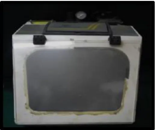
Sand blaster – Ideal blaster (Delta, Chennai) (Fig. 21)
Sputtering machine (Hitachi High Technologies Corporation, Japan)
30
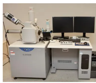
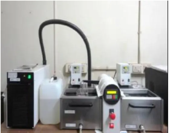
Scanning Electron Microscope (S-3400N, Hitachi High Technologies Corporation, Japan) (Fig. 23)
Light curing unit (Woodpecker, Vijay Dental Depot, India) (Fig. 24)
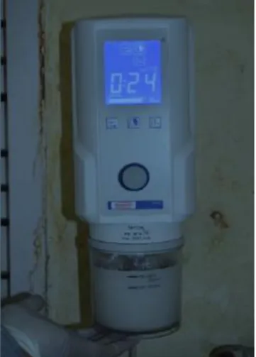
Automated Thermocycling unit (Haake Willytec, Germany) (Fig. 25)
Universal testing machine (Instron 3382 100 KN, UK) (Fig. 26)
Description of the equipment used:
Ceramic furnace (Fig. 20):
31
Scanning electron microscope (Fig. 23):
In this present study, the surface of the test samples was analyzed using Scanning Electron Microscope (S-3400N, Hitachi High Technologies Corporation, Japan). Scanning Electron Microscope uses a beam of highly energetic electrons to examine objects on a very fine scale. The specimens to be magnified are coated with a platinum layer to prevent the charging up and in order to increase the secondary emissions. Additional sputter coating with gold produces high contrast and resolution. The incident electron probe scan the sample surface and the signals produced are used to modulate the intensity of a synchronously scanned beam on a Cathode Ray Tube (CRT) screen. The electrons
which are back scattered from the specimen are collected to provide (i) topographical information, if low energy secondary electrons are collected (ii) atomic number, if high energy secondary electrons are collected. The
32
Light curing unit (Fig. 24):
Light curing unit (Woodpecker) consist of high, regular, low curing modes with interchangeable light guides, multiple curing option with periodic level shifting. The unit is wireless with three working modes as full, ramping, pulse and replaceable battery. Full charge can be used over a 400 times. LED light cures uses the principle of Ray Radiation to solidify the light sensitive resin by shooting at it in a short time. And time settings ranges from 5s, 10s, 15s, 20s, 25s, 30s, 35s, upto 40s. It has power input of AC100V-240V 50Hz/60Hz and light output of 850mW/cm² - 1000mW/cm²
Automated Thermocycling unit (Fig. 25):
33
holding the test samples. The open sample container with the test samples is immersed cyclically in baths of warm and cold water. Simulation of exposure of samples to various temperature fluctuations can reveal bond durability of the samples.
Universal testing machine (Fig. 26):
34
METHODOLOGY
The present in vitro study was conducted to comparatively evaluate the shear bond strength between repair composite resin bonded to bilayered and monolithic lithium disilicate ceramic restorations.
The methodology adopted in the present study was described under the following sections:
I. Fabrication of custom made stainless steel jig II. Fabrication of test samples
Preparation of wax patterns
Grouping of wax patterns
Fabrication of Group I test samples
Fabrication of Group II test samples
III. Surface treatment of central defect of the test samples
35
V. Filling of central defect with repair composite resin VI. Thermocycling of test samples
VII. Shear bond testing of the test samples
VIII. Qualitative analysis of the mode of failure on the repair composite resin surface by scanning electron microscope (SEM)
IX. Data tabulation and Statistical analysis
I.
Fabrication of custom made Stainless jig (Fig. 27 & 28):
36
II.
Fabrication of test samples (Fig. 29-Fig. 49)
Preparation of wax patterns (Fig.29-Fig.34):
Dental Inlay casting wax-medium (GC Corporation, Tokyo, Japan) was melted with a hot wax knife. The melted wax was added in drops into the jig space to avoid air entrapment (Fig. 30). The jig space was filled and using flushing disc the excess wax was flushed out and removed using a wax carver
(Fig. 31). The jig assembly was unscrewed and the wax pattern was removed from the jig (Fig. 32). A total of 11 wax patterns with height 3mm, diameter 10mm, with central defect of diameter 4 mm which simulates the chipped or fractured site and debonded ceramic site of the restorations were prepared for bilayered lithium disilicate ceramic test samples. (Fig. 33) A total of 11 wax patterns with height 5mm, diameter 10 mm with central defect of diameter 4mm which simulates the chipped or fractured site and debonded ceramic site of the restorations were prepared for monolithic lithium disilicate ceramic test samples.
37
Grouping of wax patterns (Fig. 33 & 34):
The fabricated wax patterns were divided into two groups.
a. Wax patterns for bilayered lithium disilicate ceramic restoration test samples- Group I (Fig. 33)
b. Wax patterns for monolithic lithium disilicate ceramic restoration test samples - Group II (Fig. 34)
Fabrication of Group I (bilayered lithium disilicate ceramic
restoration) test samples (Fig. 35-Fig. 42):
11 wax patterns for Group I (bilayered lithium disilicate ceramic) were sprued and invested with phosphate bonded investment material following the manufacturer’s instructions (Bellavest® SH, Germany) (Fig. 35 & 36). The burn out process was carried out at 900ºC (Fig. 37) after soaking time of half an hour. Lithium Disilicate monolithic ceramic press (IPS emax press, Ivoclar vivadent, Schaan, Liechtenstein) was carried out following the manufacturer’s parameters
38
400 grit size, to ensure base-line homogeneity of surface texture of all test samples.
For addition of layering ceramic, surface of the test samples were sandblasted with 50µm aluminum oxide particles at low pressure to create roughness, thereby ensuring mechanical retention for layering ceramic to the core ceramic. After sandblasting, opaque ceramic powder was added and fired under vacuum at 750ºC (Fig. 41) to form a foundation layer. After finishing the foundation layer, dentin ceramic powder was added to the thickness of 2mm and fired under 750ºC vacuum pressure (Fig. 42). Final trimming and polishing was done using sintered diamond.
Fabrication of Group II (monolithic lithium disilicate ceramic
restoration) test samples (Fig. 44-Fig. 49):
11 wax patterns for Group II were sprued and invested with phosphate bonded investment material following the manufacturer’s instructions (Bellavest® SH, Germany) (Fig. 44 & 45). The burn out process was carried out at 900ºC (Fig. 46) after soaking time of half an hour. Lithium Disilicate monolithic ceramic press (IPS emax press, Ivoclar vivadent, Schaan, Liechtenstein) was carried out following the manufacturer’s parameters (Fig. 47).
39
Divesting was done (Fig. 48) using glass beads followed by ultrasonic cleaning with 1% hydrofluoric acid. After divesting and cleaning, sprues were removed using diamond disk (Fig. 49). The samples were then finished with silicon carbide wheel. Each sample was finished with water emery paper of 220, 320 and 400 grit sizes, respectively starting from 220 and progressing finally to 400 grit size, to ensure base-line homogeneity, of surface texture of all test samples.
III.
Surface treatment of central defect of test samples (Fig.
51-Fig. 54):
The surface of defect well of test samples from groups I &II were etched with 5% HF for 20 seconds. The samples were then rinsed with distilled water for 1 minute and air dried. (Fig. 50-Fig. 54)
IV.
Qualitative analysis of surface characteristics of the etched
surface of test samples by Scanning Electron Microscope (SEM)
(Fig. 55-Fig. 56):
40
gold sputtering system. The coated sample was examined at 2000X magnification to qualitatively assess the surface characteristics (Fig. 55 & 56)
V.
Filling of central defect with repair composite resin (Fig.
57-Fig. 65):
Following etching of the test sample with 5% HF for 20 seconds, it was rinsed with distilled water for 1 minute and air dried. Next, Silanization was done using a silane coupling agent (Monobond N, Ivoclar Vivadent, Schaan, Liechtenstein) following the manufacturer’s instructions. The silane coupling agent was applied to the defect well using a brush and allowed to react for 60s
41
VI.
Thermocycling of test samples (Fig. 66-Fig. 67):
The test samples were stored in distilled water in individual containers for 24 hours at 37ºC. (Fig. 66) Then the test samples were subjected to thermocycling for a total of 250 cycles in a distilled water bath between 5ºC and 55ºC with a dwell time of 60 seconds and a dry time of 10 seconds at 27ºC between the warm and cold cycles using a thermocycling apparatus (Haake, W15, Germany) to simulate three months of clinical use. The test samples of each group were tied in a cloth pouch and the two sets of pouch were collectively thermocycled in the apparatus (Fig. 67). Upon completion of thermocycling, the test samples were again stored in distilled water in their respective containers till they were subjected to shear bond testing.
VII.
Shear bond testing of the samples (Fig. 68):
42
Newton (N) and shear bond strength (MPa) was calculated by dividing the force (N) at which failure of the bond occurred by the surface area of adhesion (mm2). The tested samples were stored in distilled water.
Bond Strength (MPa) =Force (N) /surface area (mm2)
VIII.
Qualitative analysis of the mode of failure on the repair
composite resin surface by Scanning Electron Microscope (SEM)
(Fig. 69-Fig. 70):
43
IX.
Data tabulation and statistical analysis
ANNEXURE I
METHODOLOGY OVERVIEW
Fabrication of test samples (n=22) Preparation of wax patterns
Application of silane coupling agent for 60s and air dried Application of bonding agent and light cured for 10s
Incremental addition of repair composite resin over the test surface Samples stored under distilled water for 24hrs at 37ºC
Samples subjected to thermocycling for a total of 250 cycles between 5ºC and 55ºC with a dwell time of 60s and a dry time of 10s
Shear bond strength testing individually using universal testing machine until failure of the bond occurred
SEM analysis of representative sample from each test group to assess mode of failure Data tabulation and statistical
analysis
Surface treatment with 5% HF for 20s washed under distilled water for 1 minute (Group I, n=11; Group II, n=11)
SEM analysis of etched surface topography of representative sample of Group I & Group II (Group I, n=1; Group II, n=1)
Interpretation of results Repair procedures of test samples for shear bond
testing (Group I, n=10; Group II, n=10)
Fabrication of custom made stainless steel jig
ANNEXURE II
MATERIALS
[image:69.595.216.411.202.329.2]
Fig. 1: Inlay wax
Fig. 2a. Sprue wax 3.5mm Fig. 2b. Silicone casting ring Fig. 2c. Crucible former
Fig. 2d. Aura film Surfactant spray
[image:70.595.215.381.109.244.2]
Fig. 4: Silicon carbide paper 220, 320, and 400 grits
Fig. 5: Trimming and polishing kit 5a: Carborundum disc, tungsten
carbide metal trimming burs, mandrel & silicon wheel
5b: Diamond abrasive & white wheel
[image:70.595.233.368.289.427.2]Fig. 6: Lithium disilicate ingots (IPS emax press)
[image:71.595.224.376.108.259.2]Fig. 7: IPS emax ceram powder dentin 20g
Fig. 10: Repair composite (Ivoclar Vivadent Ceramic Repair N Kit)
[image:72.595.224.370.45.258.2] [image:72.595.218.340.515.687.2]Fig. 12: Bonding agent (Heliobond)
Fig. 13: Repair composite resin ( Tetric N-ceram)
[image:73.595.213.375.499.648.2]INSTRUMENTS
Fig. 16: Wax carver
EQUIPMENTS
[image:75.595.208.389.171.423.2]Fig. 18: Vacuum mixer
Fig. 24: Light curing unit Fig. 23: Scanning electron microscope
[image:78.595.158.438.136.356.2]
Fig. 25: Automated Thermocycling unit
METHODOLOGY
I.
Fabrication of custom made stainless steel jig
Fig. 27: Customized stainless steel jig 27a. Main body
27b. 5mm spacing disc 27c. 2mm spacing disc 27d. Wax Flushing disc 27e. Central defect rod 27f. Locking screw
Fig. 28: Increment jig 28a. 2mm 28b. 1mm
a
Fig.15: Wax carver Fig.15: Wax knife
b c d
e f
27g. CAD diagram of jig
28c. CAD diagram
II.
Fabrication of test samples
[image:80.595.205.412.265.521.2]Preparation of wax patterns
Fig. 29: Assembled jig
Fig. 30: Wax poured into mould space
Fabrication of Group I test samples (Bilayered
lithium dislicate ceramic restoration)
[image:81.595.226.370.516.713.2]Fig. 33: Wax patterns (Group I) Fig. 34: Wax patterns (Group II)
Fig. 36: Investing
Fig.37: Burnout procedure
Fig. 38: Ceramic Ingot heat press
Fig. 40: Sprue removed
Fabrication of Group II test samples (Monolithic lithium
disilicate ceramic restoration)
Fig. 43: Completed Bilayered lithium disilicate ceramic restoration (Group I)
[image:85.595.248.352.551.690.2]Fig.1: Lithium disilicate with layering technique (Group I)
Fig. 42: Ceramic firing of layering ceramic
Fig.45: Investing
Fig.46: Burnout procedure
Fig.50: Completed Monolithic lithium disilicate ceramic restoration (Group II)
Fig.1: Lithium disilicate with layering technique (Group I)
Fig.48: Divested ceramic samples
III.
Surface treatment of central defect of the test samples
[image:89.595.208.388.108.326.2]
Fig. 53: Distilled water rinsing
[image:89.595.217.399.420.641.2]IV.
Qualitative analysis of the surface characteristics of the
etched surface of test samples by scanning electron
[image:90.595.209.388.194.362.2]microscope (SEM)
Fig. 55: Gold sputtering of etched test samples prior to SEM analysis
[image:90.595.226.398.443.677.2]V.
Filling of central defect with repair composite resin
Fig. 59: Bonding agent
Fig. 61: Light curing of the bonding agent
Fig. 63: Repair composite placed inside the increment jig
Fig. 65: Light curing the composite in increments
VI.
Thermocycling procedure
VII.
Shear bond testing of test samples
Fig. 67: Thermocycling of the test samples
Fig. 68: Shear bond strength testing of test samples in universal testing machine
VIII.
Qualitative analyses of the mode of failure on the
repair composite resin surface by Scanning Electron
Microscope (SEM):
Fig. 69: Gold sputtering of debonded test samples
44
RESULTS
The present in vitro study was conducted to comparatively evaluate the shear bond strength between repair composite resin bonded to bilayered and monolithic lithium disilicate ceramic restorations.
Lithium disilicate test samples bilayered and monolithic were fabricated from the wax pattern. Samples of both the groups were etched with 5% hydrofluoric acid for 20 seconds. One representative test sample from each group was randomly selected and qualitatively analysed using scanning electron microscope under 2000X magnification and the etched surface topography was observed and images were obtained.
Remaining test samples, after silanization were filled with repair composite resin and light cured. The samples were subjected to thermocycling simulating three months duration. After thermocycling samples were subjected to shear bond strength testing using universal testing machine and the data obtained were tabulated and statistically analysed using non-parametric Mann-Whitney U-test.
45
The following results were drawn from the study:
Table I shows the basic data and mean shear bond strength between repair composite resin bonded to bilayered lithium disilicate ceramic restoration.
Table II shows the basic data and mean shear bond strength between repair composite resin bonded to monolithic lithium disilicate ceramic restoration.
Table III shows comparative evaluation of the mean shear bond strength of repair composite resin bonded to bilayered lithium disilicate ceramic restoration (Group I) and repair composite resin bonded to monolithic lithium disilicate ceramic restoration (Group II) using non-parametric Mann Whitney U test.
Graph I shows the Basic data of shear bond strength between repair composite resin bonded to bilayered lithium disilicate ceramic restoration (Group I)
Graph II shows the Basic data of shear bond strength between repair composite resin bonded to monolithic lithium disilicate ceramic restoration (Group II)
46
Fig. 71: SEM photomicrograph under 2000X magnification of etched surface of representative sample (Group I) after 20s of etching, Group I sample surface (nano fluorapatite ceramic) revealed presence of both undissolved and dissolved surface topography. Patches of etched ceramic surface showing microporosites with poorly-defined pits were observed. There were significant areas of unetched ceramic surface present throughout the observed field.
Fig. 72: SEM photomicrograph under 2000X magnification of etched surface of representative sample (Group II) after 20s of etching, Group II sample surface (Lithium disilicate) revealed significant change in surface microstructure as compared to that observed for Group I etched surface. The etched surface showed, a predominantly irregular surface characterized by the numerous microporositites in the form of pits, grooves and few striations, that were present throughout the observed field. Fewer areas of undissolved glassy phase of lesser dimensions were also visible, interspersed between the predominantly etched surface.
Fig. 73: SEM photomicrograph under 2000X magnification of mode of failure on the repair composite resin surface of (Group I) showed , a predominantly smoothen resin surface with sparsely distributed isolated areas of ceramic material were visible, indicative of a mixed mode of failure that was predominantly adhesive in nature between repair resin and ceramic. The mode of failure pattern observed was indicative of a vulnerable bond at the ceramic-repair resin interface.
ANNEXURE III
QUALITATIVE ANALYSIS OF ETCHED SURFACE BY
SCANNING ELECTRON MICROSCOPY (SEM)
Fig. 71: SEM photomicrograph of representative etched
surface of Group I test sample before repair composite resin
filling under 2000X magnification
Inference:
[image:102.612.187.426.219.403.2]QUALITATIVE ANALYSIS OF ETCHED SURFACE BY
SCANNING ELECTRON MICROSCOPY (SEM)
Fig. 72: SEM photomicrograph of representative etched
surface of Group II test sample before repair composite resin
filling under 2000X magnification
Inference:
47
Table I: Basic and mean shear bond strength (MPa) of repair
composite resin bonded to bilayered lithium disilicate ceramic
restoration (Group I)
Inference
Group I exhibited maximum shear bond strength value of 8.32MPa and minimum shear bond strength value of 3.19MPa. The mean shear bond strength was 5.34MPa.
Sample no
Shear bond
strength in MPa
1 6.40
2 5.32
3 4.70
4 5.59
5 5.70
6 4.03
7 8.32