Rochester Institute of Technology
RIT Scholar Works
Theses Thesis/Dissertation Collections
2-1-2010
Performance analysis of a scalable hardware FPGA
Skein implementation
Aric Schorr
Follow this and additional works at:http://scholarworks.rit.edu/theses
This Thesis is brought to you for free and open access by the Thesis/Dissertation Collections at RIT Scholar Works. It has been accepted for inclusion in Theses by an authorized administrator of RIT Scholar Works. For more information, please [email protected].
Recommended Citation
Performance Analysis of a Scalable Hardware FPGA
Skein Implementation
by
Aric Schorr
A thesis submitted in partial fulfillment of the requirements for the degree of Master of Science in Computer Engineering
Supervised by
Prof. Marcin Łukowiak
Department of Computer Engineering Kate Gleason College of Engineering
Rochester Institute of Technology Rochester, New York
February 2010
Approved By:
Prof. Marcin Łukowiak
Department of Computer Engineering
Prof. Stanisław Radziszowski Department of Computer Science
Prof. Alan Kaminsky
Department of Computer Science
Prof. Roy Melton
Thesis Release Permission Form
Rochester Institute of Technology
Kate Gleason College of Engineering
Title: Performance Analysis of a Scalable Hardware FPGA Skein
Imple-mentation
I, Aric Schorr, hereby grant permission to the Wallace Memorial Library reproduce my
thesis in whole or part.
Aric Schorr
Dedication
To my family
Acknowledgments
Thank you to all of my thesis advisers for their help and guidance throughout this process.
Thanks especially to Dr. Marcin Łukowiak, with whom I have had the pleasure of learning
from for many years, on many projects. And last but not least, thank you to all the members
of the second home we affectionately call “our lab,” for making all the hours spent at school
Abstract
Hashing functions are a key cryptographic primitive used in many everyday applications,
such as authentication, ensuring data integrity, as well as digital signatures. The current
hashing standard is defined by the National Institute of Standards and Technology (NIST)
as the Secure Hash Standard (SHS), and includes SHA-1, SHA-224, SHA-256, SHA-384
and SHA-512 . SHS’s level of security is waning as technology and analysis techniques
continue to develop over time. As a result, after the 2005 Cryptographic Hash Workshop,
NIST called for the creation of a new cryptographic hash algorithm to replace SHS. The
new candidate algorithms were submitted on October 31st, 2008, and of them fourteen have
advanced to round two of the competition. The competition is expected to produce a final
replacement for the SHS standard by 2012.
Multi-core processors, and parallel programming are the dominant force in computing,
and some of the new hashing algorithms are attempting to take advantage of these resources
by offering parallel tree-hashing variants to the algorithms. Tree-hashing allows multiple
parts of the data on the same level of a tree to be operated on simultaneously, resulting in
the potential to reduce the execution time complexity for hashing from O(n) to O(log n).
Designs for tree-hashing require that the scalability and parallelism of the algorithms be
researched on all platforms, including multi-core processors (CPUs), graphics processors
(GPUs), as well as custom hardware (ASICs and FPGAs). Skein, the hashing function
that this work has focused on, offers a tree-hashing mode with different options for the
maximum tree height, and leaf node size, as well as the node fan-out.
This research focuses on creating and analyzing the performance of scalable hardware
sequential hashing cores, and create scalable control logic in order to provide for
high-speed and low-area parallel hashing hardware are presented and analyzed. Equations were
created to help understand the expected performance and potential bottlenecks of Skein
in FPGAs. The equations are intended to assist the decision making process during the
design phase, as well as potentially provide insight into design considerations for other tree
hashing schemes in FPGAs. The results are also compared to current sequential designs of
Contents
Dedication. . . iii
Acknowledgments . . . iv
Abstract . . . v
1 Introduction to NIST Competition . . . 1
1.1 Motivation . . . 1
1.2 Candidate Algorithms . . . 2
1.3 Skein Security Claims . . . 2
2 Skein Overview . . . 3
2.1 Unique Block Iteration . . . 6
2.1.1 Key UBI . . . 8
2.1.2 Configuration UBI . . . 8
2.1.3 Output UBI . . . 9
2.2 Message Processing . . . 9
2.2.1 Tree Hashing . . . 10
2.3 Threefish . . . 12
2.3.1 MIX and Permute . . . 14
2.3.2 Key Scheduler . . . 16
3 Supporting Work . . . 20
3.1 Iterative and Unrolled Architecture . . . 20
3.1.1 Iterative Round Architecture . . . 21
3.1.2 Round Unrolling Architecture . . . 22
3.2 Eight-Round Unrolled Approach . . . 23
4 Design Methodology and Results . . . 27
4.1 Sequential Skein . . . 27
4.1.1 Iterative Model . . . 28
4.1.2 Unrolled Model . . . 31
4.1.3 Performance Evaluation . . . 36
4.2 Tree Skein . . . 37
4.2.1 Duplicate Core Model . . . 39
4.2.2 Pipelined Core Model . . . 42
4.2.3 Software Controlled Model . . . 42
4.2.4 Performance Evaluation . . . 43
4.3 Message Delivery . . . 47
4.4 Design Testing and Verification . . . 52
4.4.1 VHDL Model Verification . . . 52
4.4.2 Hardware Implementation Verification . . . 53
5 Conclusions . . . 55
Bibliography . . . 57
List of Figures
2.1 Matyas-Meyer-Oseas Construction . . . 3
2.2 Skein Unkeyed and Keyed Hashing . . . 5
2.3 Skein with2∗ISbits < OSbits ≤3∗ISbits. . . 5
2.4 UBI with M of length 3*ISbits . . . 6
2.5 Skein Tree Hashing . . . 11
2.6 Skein Tree Parameters and Structure . . . 12
2.7 Threefish Block Diagram . . . 13
2.8 MIX Function . . . 15
2.9 Rounds 0 to 4 of Threefish-256 and Threefish-512 . . . 17
2.10 Initial Subkey Generator State . . . 19
2.11 Next Subkey Generator State . . . 19
3.1 Long Iterative Architecture for Threefish [6] . . . 21
3.2 Long Internal Round Logic for Threefish-256 [6] . . . 22
3.3 Long Unrolled Architecture for Threefish . . . 23
3.4 Tillich Unrolled Architecture [13] . . . 25
4.1 Iterative Model Core . . . 29
4.2 4-1 Multiplexer in Virtex-5 . . . 29
4.3 MIX Rotation Hardware . . . 30
4.4 Key Schedule Unit for Threefish-256 [13] . . . 34
4.5 Unrolled Threefish Core [13] . . . 34
4.6 Skein State Machine . . . 35
4.7 Effect of Overhead/Stall Cycles on Sequential Skein . . . 38
4.8 Round Robin Core Assignment Strategy . . . 40
4.9 UBI Memory Read/Store Methodology . . . 41
4.10 Maximum Theoretical Speed UpYF = 8 . . . 46
4.11 Skein Tree Growth . . . 46
4.12 Maximum Theoretical Speed Up . . . 48
List of Tables
2.1 Skein Arguments . . . 4
2.2 The Tweak Fields [10] . . . 8
2.3 The Configuration String [10] . . . 9
2.4 Threefish Variable Definitions . . . 13
2.5 Threefish Algorithm . . . 14
2.6 Threefish MIX Algorithm . . . 14
2.7 Threefish Rotation Values . . . 15
2.8 Threefish Permutation Values . . . 16
2.9 Threefish Key Scheduling Algorithm . . . 18
3.1 FPGA Results from [6] . . . 24
3.2 Stefan Tillich Results [13] . . . 25
4.1 Subkey Hardware for Skein-512 . . . 30
4.2 Iterative Results . . . 31
4.3 Skein State HW Control Logic Variables . . . 32
4.4 Skein State HW Control Logic Algorithm . . . 33
4.5 Unrolled Results . . . 35
4.6 Skein Sequential Variable Definitions . . . 37
4.7 Skein Tree Performance Variable Definitions . . . 44
4.8 Calculating the UBI nodes in a Skein Tree . . . 44
4.9 Message Block Handshaking . . . 51
Chapter 1
Introduction to NIST Competition
The National Institute of Standards and Technology (NIST) is a US federal agency
dedi-cated to promote innovation by advancing standards in science and technology. According
to the Computer Security Division’s (CSD) mission statement, its focus is protecting
infor-mation against threats to the confidentiality and integrity of data. NIST CSD suggests and
standardizes several hashing algorithms to help protect data integrity; these are known as
the Secure Hash Algorithms (SHA) [3].
1.1
Motivation
“Cryptanalysts have found collisions on the MD4, MD5, and SHA-0 [hashing] algorithms;
moreover, a method for finding SHA-1 collisions with less than the expected amount of
work has been published . . . [although] have not yet been demonstrated [11].” Because of
the vulnerabilities that exist in SHA-1 and may exist in SHA-2, and the devastating effects
that these vulnerabilities could cause, NIST has called for the creation of a new standard
by means of a public competition. This competition is intended to be similar to the one
that decided on AES as an encryption standard. Candidates will go through a few years of
public scrutiny, where cryptanalysts will analyze the security of the candidate algorithms,
while computer scientists and engineers will analyze the performance of the candidates
on different platforms. It is important to find an algorithm that will perform well while
This work is aimed at providing support to NIST’s Cryptographic Hash Algorithm
Competition. The public comment period for round two is scheduled to end during the
second quarter of 2010, and this work will provide a thorough performance analysis of the
candidate algorithm Skein. The performance analysis covers both sequential and scalable
tree-hashing versions in hardware, and compares the results to other published work related
to Skein and the NIST competition.
1.2
Candidate Algorithms
The call for algorithms by NIST produced 64 different submissions from all over the world.
Only 51 of the 64 submission met the requirements set by NIST to make it to the first round.
From there, after the First SHA-3 Candidate Conference, which took place in Leuven,
Belgium (FEB 2009), the pool was reduced to only 14 remaining algorithms: BLAKE,
Blue Midnight Wish, CubeHash, ECHO, Fugue, Grøstl, Hamsi, JH, Keccak, Luffa, Shabal,
SHAvite-3, SIMD, and Skein. The 14 algorithm candidates will undergo a second round
of public review for cryptographic and performance comments. This work gives a full
performance analysis of scalable hardware designs of Skein, as well as provides in-depth
examples and techniques for FPGA implementations [2].
1.3
Skein Security Claims
Skein was designed to be simple, fast, and secure [10]. It is simple and fast in that at
its core, Skein uses only three primitive operations: exclusive or, unsigned addition, and
rotations. The security of Skein against standard attacks on hashing functions is claimed
to be 2m for both first and second pre-image resistance, and2m/2 for collision resistance, where m is the minimum of the internal state and output size of the implementation. A
more in-depth security analysis of Skein is giving in [7]. This work will not focus on the
Chapter 2
Skein Overview
Skein [10] is one of the fourteen proposed hashing algorithms that have advanced to the
second round of the NIST SHA-3 competition [3]. The algorithm’s main authors are Niels
Ferguson and Bruce Schneier, who are also known as the authors of “Practical
Cryptog-raphy” [4]. The design of the hashing algorithm is based on a block cipher using the
Matyas-Meyer-Oseas (MMO) construction, Threefish block cipher, and an additional
wrap-per around the MMO known as the Unique Block Iteration (UBI). The
Matyas-Meyer-Oseas construction (Figure 2.1) takes an n-bit message block (Mi) into the plaintext input
of the block cipher and ann-bit previous hash value (Hi−1) into the key input to determine
theHi =EHi−1(Mi)⊕Mi whereE can be any block cipher [9].
Figure 2.1: Matyas-Meyer-Oseas Construction
Skein builds on the Matyas-Meyer-Oseas construction with an argument system and
Table 2.1: Skein Arguments
Skein Arguments
Symbol Value Description
Tkey 0 Key
Tcf g 4 Configuration Block
Tprs 8 Personalization String
TP K 12 Public Key
Tkdf 16 Key Identifier
Tnon 20 Nonce
Tmsg 48 Message
Tout 63 Output
order, with the most common arguments being key (Tkey), configuration (Tcf g), message
(Tmsg), and output (Tout). The only required steps in Skein are the configuration, message,
and output step; the key stage and other optional arguments allowed in the system are
spec-ified in Table 2.1. These are processed in order of their value from least to greatest, and
are provided as part of the tweak type input as described in Table 2.2. Thus for normal
unkeyed hashing of a message, a digest would be produced by a configuration block, then
message, and finally an output block, whereas keyed Skein for use as a message
authen-tication code (MAC) or key derivation function (KDF) would require a key block, then
configuration, then message, and finally an output block, as shown in Figure 2.2. A more
complete description of the UBI function can be found in Section 2.1.
Skein can be configured using several different parameters that affect the internal
op-erations. The naming convention of Skein indicates the internal block size in bits (ISbits)
as well as the output digest size in bits (OSbits) and is written as Skein-ISbits-OSbits. The
value ofISbits can be one of three different internal state sizes: 256, 512, or 1024, while
Skein supports any size for OSbits up to 264. Each UBI output is the same size asISbits,
and in order to support larger values ofOSbits multiple output blocks are run as shown in
Figure 2.3; the input to each output block is shown as the decimal value of an unsigned
Figure 2.2: Skein Unkeyed and Keyed Hashing
2.1
Unique Block Iteration
The Unique Block Iteration that is responsible for each argument in Skein requires that
three inputs be provided: a chaining variable (G), a message or data portion of arbitrary bit
length up to (299−8) bits or (296−1) bytes (M), and a starting 128-bit tweak value (Ts).
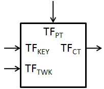
It returns a single output of sizeISbits as shown in equation 2.1. The UBI is the
Matyas-Meyer-Oseas construction with the tweakable block-cipher known as Threefish (Figure
2.4). The internals of Threefish will be discussed in a later section, but it is important to
know that Threefish requires three inputs: plaintext of sizeISbits(T FP T), key of sizeISbits
(T FKEY), and a tweak of size 128-bits (T FT W K), and gives a single ciphertext output of
sizeISbits(T FCT).
H =U BI(G, M, Ts) (2.1)
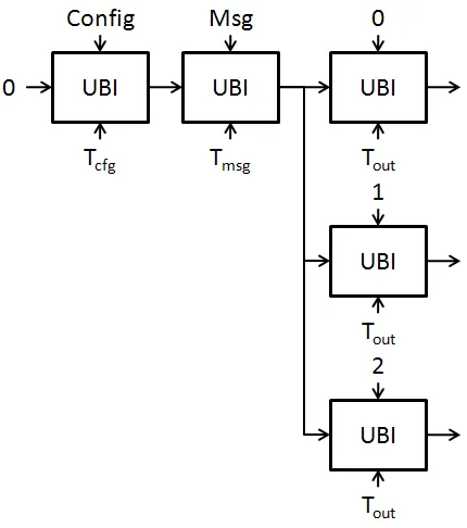
Figure 2.4: UBI with M of length 3*ISbits
The length of the message determines how many blocks of Threefish are chained
to-gether within each UBI. The message input of the UBI (M) is split intok message blocks
M0, . . . , Mk−1 of size ISbits, and each block of M is fed into the T FP T Threefish
in-put. Thus, if the length of the message (M) in bits is Mbits, then the UBI will need
dMbits/ISbitse Threefish blocks chained together, (e.g. the message shown in Figure 2.4
has a message length of: 2∗ISbits < Mbits ≤ 3∗ISbits). If the message length is not a
“0” bits as needed to make the message a multiple ofISbits.
The tweak input for all variants of Skein (256, 512, or 1024) is a 128-bit value that
contains seven different fields, shown in Table 2.2. The Final tweak field is a single bit that
is set only during the final block of Threefish in the UBI, meaning in Figure 2.4T2 would
have the Final bit set to “1”, whileT0andT1 would have the Final bit set to “0”. Likewise,
the First bit is set only for the first block of Threefish; thusT0 would have its First bit set
to “1” and T1 andT2 would have the First bit set to “0”. In the case that there is only a
single block of Threefish to process in a UBI, such as in the configuration or output stages,
both the First and Final bit are set. The Type field contains the numerical value of the Skein
argument, as shown in Table 2.1, that is being processed. The type field remains the same
for every ThreefishT FT W Kin a single UBI. The BitPad field is set to “1” only if this is the
final Threefish block and the last byte in the unpadded message was not a full byte. This
means that the Mbits mod 8 6= 0. The TreeLevel field is zero for sequential Skein, or is
the level of the tree where this UBI is located, with the leaf level being equal to 1. Tree
hashing in Skein will be explained in later sections. The position field is the number of
bytes including the current block, but not including padding, of the message that has been
processed thus far. For tree hashing this value gets reset to zero when a new level of the tree
is reached. All of the tweak fields are well-defined, and it should be noticed that the value
of the tweak is not determined by the user, but rather the algorithm and stage of processing
that is being conducted.
The chaining variable (G) typically comes from the output of the previous UBI. As
seen in Figure 2.4, the message stage’s chaining variable is the output of the configuration
UBI, and the output stage’sGcomes from the output of the message UBI. If this is the first
UBI of processing, either configuration (Tcf g) for unkeyed hashing or key (Tkey) for keyed
hashing, then the value ofGis the zero vector. The internal UBI process can be represented
by equation 2.2.
Table 2.2: The Tweak Fields [10]
The Tweak Fields
Name Bits Description
Final 127 Set for first Threefish block in a UBI compression First 126 Set for last Threefish block in a UBI compression Type 125-120 Numerical value of Skein Argument (Tcf g,Tmsg,Tout, etc)
BitPad 119 Set if this block contains the last byte of an input whose length was not an integral number of bytes TreeLevel 118-112 Level in the hash tree, zero for non-tree computations
Reserved 111-96 Reserved for future use, must be zero
Position 95-0 The number of bytes in the string processed so far (including this block)
2.1.1
Key UBI
Handling of key occurs before any other message processing as indicated by the value of
Tkey equal to zero. Skein defines the output of the key stage as K0, for a given input key
K of length Nk bytes. If no key is given (Nk = 0), then K0 is also equal to the zero
vector; otherwise the key K must be processed using a UBI function. Using equation 2.1
to represent the key UBI gives equation 2.3.
K0 =U BI(0, K, Ts); IfNk>0 (2.3)
2.1.2
Configuration UBI
The configuration UBI is a required stage of any Skein processing, and uses what is known
as the configuration string (C) as the message input to the UBI. The configuration string is
a 256-bit long message containing eight different fields, shown in Table 2.3. The schema
identifier is a constant used to identify how the UBI and Threefish blocks are used to create
a message digest; for this work all that matters is this is a constant that will not be altered.
The version number and reserved fields are present to allow for future extensions. The
Table 2.3: The Configuration String [10]
The Configuration String
Name Offset Size (Bytes) Description
Schema ID 0 4 ASCII String “SHA3”
Version # 4 2 Currently 1
Reserved 6 2 Set to 0
Output Length 8 8 Desired output length in bits
Tree Leaf Size 16 1 YL
Tree Fan-Out 17 1 YF
Maximum Tree Height 18 1 YM
Reserved 19 13 Set to 0
parameters (YL,YF, YM) and their effects are discussed later in the Tree Hashing section,
but for now are all set to zero if tree hashing is not used. With all of these fields making up
the configuration string (C), the Configuration UBI is processed using equation 2.4.
G0 =U BI(K0, C, Ts) (2.4)
2.1.3
Output UBI
The output function is the final stage required and will produce exactlyOSbitsthat represent
the message digest. Since each UBI function produces exactly ISbits, the output function
will require exactly dOSbits/ISbitse UBI functions, as shown in Figure 2.3, and trims the
results atOSbits. The output function of Skein is represented by equation 2.5.
O =U BI(G,0, Ts)||U BI(G,1, Ts)||U BI(G,2, Ts). . . (2.5)
2.2
Message Processing
The actual processing of the message occurs during the Tmsg stage of Skein. This can be
simple as a single UBI, as shown in Figure 2.4, whereM is the message, T is the tweak
as defined by Skein, and G is the output of the previous UBI, usually the configuration
stage. While on the other hand, tree-mode defines a much more complex way to handle
the compression of a message. The tree parameters leaf-size (YL), node-fanout (YF), and
maximum-tree-level (YM) can each be given values between 1 and 255, representing a very
large number of possible combinations of these parameters, each resulting in a different
tree structure used to process the message. The next section sheds light on what these
parameters mean, and how they are used to build the tree.
2.2.1
Tree Hashing
Tree hashing in Skein affects only the message (Tmsg) stage of Skein. All other required
phases occur as they would in sequential Skein as shown in Figure 2.2, except the single
TmsgUBI is replaced with a tree structure. Each node of the tree is a UBI, and it is important
to understand where the inputs (G,M, andT) for each node come from. The simplest input
is the chaining variable (G); no matter the location in the tree, all UBIs receive the output
of the previous stage as their chaining variable. The fields of the tweak are generated
as described by Table 2.2, except now the tree level is included, and the position field
represents the number of bytes processed at the current level, including the bytes processed
by previous UBI nodes on the same level. The message is distributed in its entirety to the
leaf level of UBIs, and then the outputs are concatenated together to form the message
inputs for UBIs at the next level of the tree as shown by Figure 2.5.
The three input parameters that determine the size and structure of the tree are leaf
size (YL), node fan-out (YF), and maximum-tree-height (YM), and are given during the
configuration stage as a part of the configuration string. The leaf-size parameter determines
how many bits of the message are given to each leaf UBI of the tree such that each node
receives ISbits ∗ 2YL bits of the message. The node fan-out determines how many UBI
results from the previous level are concatenated together to be supplied as an input to the
Figure 2.5: Skein Tree Hashing
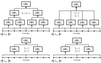
Several different tree structures generated from a message of the same size is shown in
Figure 2.6. Notice that the bottom two trees are identical despite differences in the value
of YF. This occurs because the message size and value of YL produce only two nodes,
while the fanout can take up to2YF = 4UBI outputs. The maximum-tree-height parameter gives exactly what its name implies—the maximum allowed height of the tree. The leaf’s
level index equals “1”, and YM must be greater than or equal to 2 for tree-mode. At the
level equal to YM all UBI outputs from the previous level are concatenated together and
provided as a single message input to the root node. If YM were given a value of 2, then
the tree shown in Figure 2.6 with YL = YF = 1 would end up like the tree withYL = 1,
YF = 2.
Equations describing the tree are given such that the original message (M) is split into
kblocksM0,0, M0,1, M0,2, . . . , M0,k−1each of lengthISbits∗2YLbits. The leaf level is then
constructed and processed using equation 2.6, resulting inM1. Then each level is split into
k blocks again of lengthISbits∗2YF bits, and the next level is processed using equation 2.7.
This occurs until the tree reaches its root node naturally, or it reaches the level equal toYM.
If this occurs then the final level is processed using equation 2.8 [10].
Figure 2.6: Skein Tree Parameters and Structure
Ml+1 =kik=0−1 U BI(G, Ml,i, T) (2.7)
Go =U BI(G, MYM−1, T) (2.8)
2.3
Threefish
The last piece of Skein is the Threefish block cipher used inside the UBI. Threefish is a
“tweakable block cipher,” which means that in addition to the standard key and plaintext,
there is also a tweak input. The tweak is introduced to “stop a large variety of cut-and-paste
attacks; a message piece that produces one result in one location will produce a different
result in a different location [10].” The three different internal state sizes available to Skein
(ISbits= 256, 512, or 1024 bits) come directly from the fact that these are the same internal
Table 2.4: Threefish Variable Definitions
Threefish Variable Definitions
Nw number of 64-bit words in each message/key block (ISbits/64)
Nr number of rounds in the block cipher (72 forISbits= 256 or 512, and 80 for 1024)
i word index (0, . . . , Nw−1)
j word index (0, . . . , Nw/2−1)
d current round (0, . . . , Nr−1)
vd,i ith word of state after d rounds
pi 64-bit block of plaintext or message block input
ci 64-bit block of ciphertext or output block input
output of T FCT of length ISbits, and the three inputs: T FT W K, T FP T, and T FKEY of
lengths 128-bits,ISbits, andISbitsrespectively. Internally Threefish’s encryption algorithm
operates on 64-bit words and uses a key scheduler, and round function containing subkey
addition, a MIX function, and fixed word permutation. For the remainder of this section
the text and algorithms use variables from Table 2.4.
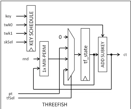
Figure 2.7: Threefish Block Diagram
The algorithm is round based, requiring 72 rounds for Threefish-256 and 512, and 80
rounds for Threefish-1024. The internal operations occur on 64-bit words, and because of
this the input of length ISbits is split into Nw words such that the T FP T would become
T FP T,0, T FP T,1, . . . , T FP T,Nw−1. As shown in the algorithm in Table 2.5, the round
num-ber (d) counts from the value 0 toNr−1, with every fourth round having a 64-bit unsigned
subkey addition to the internal state. The next step is a MIX function, and then a
Table 2.5: Threefish Algorithm
Threefish Algorithm
v0,i=T FP T,i
for d = 0; d < Nr; d++
if d mod 4 = 0 then add subkey
ed,i = (vd,i+skd/4,i)mod264
else
ed,i =vd,i
(fd,2j, fd,2j+1) = M IX(ed,2j, ed,2j+1) vd+1,i =fd,π(i)
T FCT,i = (vNr,i+skNr/4,i)mod2
64
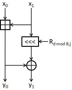
Table 2.6: Threefish MIX Algorithm
MIX Algorithm
(y0, y1) = M IX(x0, x1) y0 = (x0+x1)mod264
y1 = (x1 <<< Rdmod8,j)⊕y0
subkey addition to the internal state to make the ciphertext output.
2.3.1
MIX and Permute
The MIX operation is the main function in a Threefish round, shown in Table 2.6 and Figure
2.8. Each MIX block takes in two 64-bit inputs, and gives two 64-bit outputs. Thus, each
variant of Threefish requires a different number of MIX blocks equal to Nw/2. Internally
to each MIX block there are only three operations: an unsigned 64-bit addition, a 64-bit
exclusive OR, and a rotation. The rotation depends on the round number and the which
MIX the rotation is occurring in (j). The rotation values repeat every eight rounds, and are
Figure 2.8: MIX Function
Table 2.7: Threefish Rotation Values
MIX Rotation Values
Nw 4 8 16
d\j 0 1 0 1 2 3 0 1 2 3 4 5 6 7
0 14 16 46 36 19 37 24 13 8 47 8 17 22 37
1 52 57 33 27 14 42 38 19 10 55 49 18 23 52
2 23 40 17 49 36 39 33 4 51 13 34 41 59 17
3 5 37 44 9 54 56 5 20 48 41 47 28 16 25
4 25 33 39 30 34 24 41 9 37 31 12 47 44 30
5 46 12 13 50 10 17 16 34 56 51 4 53 42 41
6 58 22 25 29 39 43 31 44 47 46 19 42 44 25
Table 2.8: Threefish Permutation Values
Permute Values(π(i))
Nw\i 0 1 2 3 4 5 6 7 8 9 10 11 12 13 14 15
4 0 3 2 1
8 2 1 4 7 6 5 0 3
16 0 9 2 13 6 11 4 15 10 7 12 3 14 5 8 1
The permutation stage is a simple reordering of the internal state’s 64-bit words. The
internal state is viewed as an array of 64-bit blocks, and the permute stage reorders that
array, with no changes occurring within each 64-bit block. In hardware, this is a trivial
operation of hardwiring the outputs of the previous stage to the next stage with this
per-mutation taken into account, at no cost to area or performance. The perper-mutation for each
definition of Skein is shown in Table 2.8. To help with reading this table correctly, notice
that in the algorithm the equation is written as: vi =fπ(i) meaning that for Threefish-512
(Nw = 8),v6 =f0 and thatv6 6=f4.
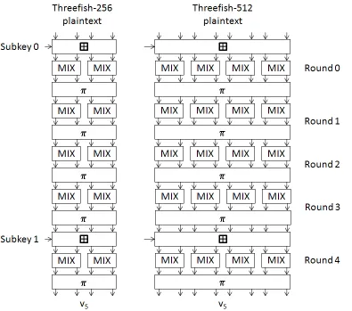
Figure 2.9 shows the structure of both Threefish-256 and 512. Each vertical arrow
represents a 64-bit word of the internal state, and the horizontal lines are a ISbits-bit
sub-key. Notice that Threefish-512 requires twice as many MIX functions for each round than
Threefish-256. The next section will discuss how the key scheduler works and what is
contained in each subkey.
2.3.2
Key Scheduler
The key scheduler is responsible for creating theNr/4 + 1subkeys of lengthISbits needed
every four rounds of Threefish. The key scheduler uses the keyT FKEY, tweak T FT W K,
and a subkey number to generate each subkey. The exact algorithm for the key scheduler
is shown in Table 2.9.
Some analysis of this algorithm will bring insight as to possible design methods for this
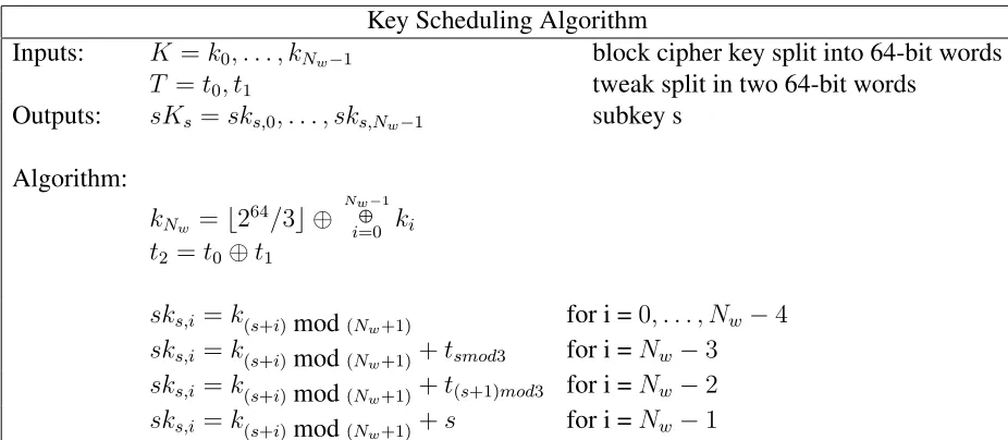
Table 2.9: Threefish Key Scheduling Algorithm
Key Scheduling Algorithm
Inputs: K =k0, . . . , kNw−1 block cipher key split into 64-bit words
T =t0, t1 tweak split in two 64-bit words
Outputs: sKs=sks,0, . . . , sks,Nw−1 subkey s Algorithm:
kNw =b2
64/3c ⊕ NwL−1 i=0 ki t2 =t0⊕t1
sks,i=k(s+i)mod(Nw+1) for i =0, . . . , Nw −4
sks,i=k(s+i)mod(Nw+1)+tsmod3 for i =Nw−3
sks,i=k(s+i)mod(Nw+1)+t(s+1)mod3 for i =Nw−2
sks,i=k(s+i)mod(Nw+1)+s for i =Nw−1
through Threefish. The internal variables to the function, kNw and t2, need to be stored,
because they are used multiple times during subkey generation. It should be noted that
kNw andt2 are not needed untils = 1. Hardware can be minimized if the order of subkey generation and speed at which it needs to be generated is taken into account.
The subkey generation module can be realized in hardware as a shift register, and three
adders. The input key and tweak are split into 64-bit words. Then the value ofkNw andt2
are generated using the 64-bit words from the input key and tweak. These values are then
loaded into registers, and each time a new subkey is needed the values in the registers are
Figure 2.10: Initial Subkey Generator State
Chapter 3
Supporting Work
Since the algorithm was published there have been two papers giving preliminary
hard-ware results, and different design strategies for Skein. The first paper was published by
Men Long of Intel Corporation, entitled “Implementing Skein Hash Function on Xilinx
Virtex-5 FPGA Platform [6].” The second paper was published by Stefan Tillich from
Graz University of Technology, entitled, “Hardware Implementation of the SHA-3
Candi-date Skein [13].” Each paper has covered important design considerations and has made
contributions to the standard sequential hashing version of Skein. This section discusses
the contributions and designs explained in [6] and [13]. This thesis will build on these
designs with suggestions and ideas for how to handle delivering the inputs to the core, as
well as how to build a scalable tree-hashing core in hardware.
3.1
Iterative and Unrolled Architecture
The first paper [6] offers an initial look into three different standard implementation
tech-niques and how they apply to Skein: iterative, unrolled, and pipelined. Each method is
discussed and results are given for only the iterative and unrolled approaches. Pipelined
is left out because the standard form of hashing is sequential and before the next round
can start processing, the data must be processed from the last round. Long states that this
may be useful for tree hashing, but that for sequential hashing all but one of the pipeline
3.1.1
Iterative Round Architecture
The iterative is the most intuitive method for implementing Skein and provides respectable
results. Since Threefish is round based, the idea is to create a single round in hardware,
and then iterate the data through this single round however many times required by the
algorithm. For the entire Threefish core to be implemented the hardware requires a subkey
generator, 64-bit adders, 64-bit exclusive ors, dynamic rotations, and wire permutations, as
well as registers to hold the data. A diagram of this hardware from Long’s paper is shown
in Figures 3.1 and 3.2.
Figure 3.1: Long Iterative Architecture for Threefish [6]
The iterative model shown in Figure 3.1 shows the basic structure needed for the
cor-rect MMO operation of Threefish. The first multiplexer chooses between the input block,
chosen for the first round of encryption, and the current state used for the remaining rounds.
The key scheduling block takes in the external key and tweak and delivers a new subkey to
the round module every four rounds. The register bank is used to retain the current state,
and the final XOR provides the MMO chaining used in the UBI of Skein.
The key scheduler used in [6] utilizes three 64-bit adders, and a MuxSwitch, as shown
in Figure 3.2. The MuxSwitch is an alternative to a shift-register approach that is used in
Figure 3.2: Long Internal Round Logic for Threefish-256 [6]
This architecture for Threefish-512 gives a throughput of 817 Mbps with a maximum
clock speed of 8.7 ns (114.9 MHz), while using 1877 slices. Long implemented his designs
on a XC5VLX50 device with a speed grade of -3 and obtained the results and those in Table
3.1. The results of Long’s iterative approach will provide the baseline for comparison with
other designs discussed in this thesis.
3.1.2
Round Unrolling Architecture
Another common method in hardware development is to perform unrolling of loops. In
the case of Skein this refers to unrolling rounds of Threefish, and will be referred to as
round-unrolling from this point forward. Long also implements a version unrolled four
rounds. This is most likely because unrolling the rounds past four results in extra subkey
generation logic. Tillich’s approach, which will be discussed in the next section, unrolls
Threefish eight rounds, which brings great advantages in throughput and area because it
requires no dynamic shifting. Long’s round-unrolled architecture, shown in Figure 3.3
By unrolling past four rounds and requiring extra subkey logic, it becomes more
im-portant which subkey generation model that is used: MuxSwitch or shift-register. The
MuxSwitch requires more logic to generate a second subkey than the shift-register
[image:35.612.200.421.187.422.2]ap-proach.
Figure 3.3: Long Unrolled Architecture for Threefish
Long’s four-round-unrolled architecture for Threefish-512 gives a throughput of 1161
Mbps with a maximum clock speed of 24.5 ns (40.8 MHz), while using 2662 slices. These
results were taken from Long’s paper and were synthesized on a XC5VLX50 device with
a speed grade of -3. The results are also shown in more detail in Table 3.1 [6].
3.2
Eight-Round Unrolled Approach
The second paper’s [13] architecture takes advantage of the fact that the rotation constants
in Threefish repeat every eight rounds, and chooses to unroll Threefish by eight rounds.
This method prevents the need for variable-size rotations in hardware, and both decreases
Table 3.1: FPGA Results from [6]
FPGA Results from [6]
Design Name Slices Used Clk (MHz) Cycles TP (Mbps)
LongIter-256 1001 114.9 72 408.7
LongIter-512 1877 114.9 72 817.4
LongUnroll-512 2662 40.8 18 1161.0
LongIter-1024 3656 84.8 80 1085.7
Device: XC5VLX50, Speed Grade: -3
iterative approach taken in [6]. This architecture requires a slower clock, but fewer clock
cycles to produce the message digest, and despite the much slower clock, because of the
fewer cycles required to compute the digest, gives greater throughput over both Long’s
iterative and unrolled approach.
3.2.1
Eight-Round Unrolled Architecture
Tillich explains that because the rotation values repeat every eight rounds,“a natural design
option is thus to unroll a multiple of eight Threefish rounds. [13]” A design with dynamic
rotations requires that there exist multiple paths for the data to exist, and drastically reduces
the Xilinx synthesis tool’s capability to reduce the design’s logic. By unrolling the design
by eight rounds and having only static rotation values, there exists only one path for the
data to travel, and this allows the synthesizer to reduce the design’s logic down to less than
Long’s iterative approach. Since Threefish needs a subkey for every four rounds, this design
requires that two subkeys be generated per clock cycle. The additional subkey generation
logic is not an issue when compared to the overall area savings and throughput increase
that result from this approach. Tillich’s full core is shown in Figure 3.4 and the results are
shown in and compared to Long’s results in Table 3.2. The core shown in Figure 3.4 gives
a complete picture of the architecture.
Overall the design is more compact by around 240 slices, or a 13% savings in area
Figure 3.4: Tillich Unrolled Architecture [13]
Table 3.2: Stefan Tillich Results [13]
Stefan Tillich Results
Design Name Slices Used Clk (MHz) Cycles TP (Mbps)
Tillich-256 937 68.4 10 1751.0
Tillich-512 1632 69.0 10 3534.8
LongIter-512 1877 114.9 72 817.4
Tillich-1024 2994 68.9 11 6414.0
2717.4 Mbps, which is an increase in throughput by 332%. These results make Tillich’s
design the clear choice for actual implementation. Neither design though takes into account
how to manage external message accesses from memory, or scalable architectures for how
to perform tree hashing in hardware. Both implementations leave it up to the designer to
choose an interface that works with their hardware and desired bus width. While this is very
understandable, this thesis will go on to describe different approaches to these interfaces,
and the important considerations that must be taken into account when designing these
Chapter 4
Design Methodology and Results
Designing for an FPGA must take into account not only the core functionality of the
hard-ware, but developing that core so that bottlenecks do not exist with any outside
peripher-als, such as memory or control logic. The goals and focus of this work are to maximize
throughput, minimize area, and provide designs with scalability in mind. Equations were
developed to help understand exactly how overhead in different areas can affect achieving
maximum throughput for a Skein hardware module. Along with overhead, this work will
also discuss strategies on how to deliver the message to the hashing core in order to
min-imize stalls and determining design decisions based on actual hardware capabilities. All
these are important issues for a designer to take into account when designing a Skein core
for actual deployment in a system.
4.1
Sequential Skein
The supporting work section covered two approaches that provide good performance, and
this section will expand on the ideas from [6] and [13] in order to give a better
understand-ing of how to use these models. The only design change was to use a register-based subkey
generator, rather than the MuxSwitch as discussed in [6]. Equations were developed as a
part of the performance evaluation section and to provide a baseline for understanding the
4.1.1
Iterative Model
The iterative model requires that a single round of Threefish be implemented in hardware.
The resulting core, based on the unrolled Tillich model [13], is shown in Figure 4.1. During
the first round, the plaintext input is chosen to be sent to the first subkey addition input,
where the result of the plaintext and subkey addition is then registered. For the remaining
71 rounds, the data flows through the MIX and permute unit, and is fed to the subkey
generator and register multiplexer. Every four rounds the subkey addition path is chosen;
otherwise the direct result of a MIX and permute is registered. After the final round, the
ciphertext is the result of a final subkey addition. The MMO operation for Skein hashing is
then handled by the XOR of the input plaintext and resulting ciphertext. The full Threefish
algorithm is given in Table 2.5.
An important consideration for the iterative model is the dynamic rotations needed
internal to the MIX operation. Because only a single round is implemented in hardware,
and the rotations vary each round, every eight rounds, a dynamic shifter must be created.
Cascaded multiplexers are one way to create such a dynamic rotation. The Xilinx Virtex-5
uses six-input look-up tables (LUT6) as the most basic logic unit. The inputs of these can
be controlled such that they act as a 4-1 MUX, as shown by Figure 4.2. For Threefish-512,
there are four sets of eight rotation values, one set for each MIX in a round of
Threefish-512. A single set of eight rotation values would, in a Virtex-5 FPGA, require two 4-1
multiplexers cascaded with a 2-1 MUX for each bit, as shown in Figure 4.3. This means
that 64 of these rotation units would be required for every MIX block, because each MIX
rotates 64-bits. This is a substantial hardware requirement compared to the eight-round
unrolled approach discussed in [13]. The only advantage of the iterative approach is that it
can operate at much faster clock frequency than the unrolled approach.
The subkey generator chosen for this model was the registered approach. This is
be-cause it is faster, requires less resources, and is more scalable than the MuxSwitch
ap-proach. The registered approach that outputs a single key (Registered) uses almost half
Figure 4.1: Iterative Model Core
Figure 4.3: MIX Rotation Hardware
Table 4.1: Subkey Hardware for Skein-512
Design Name Device/SG Bits Slices Clk(ns) Clk (MHz) % Increase
MuxSwitch XC5VLX110/-3 512 818 NA NA
MS (Unrolled) XC5VLX110/-3 512 1263 NA NA 54.40
Registered XC5VLX110/-3 512 448 0.635 1574.8
Reg (Unrolled) XC5VLX110/-3 512 480 0.639 1564.9 7.14
to be used in the eight-round unrolled approach, the MuxSwitch grows by 54.4%, while
the Registered approach only grows by 7.14%. The registered approach uses flip-flops to
rotate the tweak and key values around, and needs LUTs to perform the three additions for
each subkey. In order to scale the registered approach to create more subkeys, no more
flip-flops need to be added and only two more adder circuits are needed. The MuxSwitch
approach is far slower and requires more to be added to scale to provide two subkeys. The
single-key registered model uses 45% less resources than the single-key muxswitch, and
the double-key registered model uses 62% less resources than the double-key muxswitch.
The results provided here make the registered approach the clear choice over a MuxSwitch
approach for any Skein implementation.
The control hardware is exactly the same as in the unrolled model explained in Tables
4.3 and 4.4, except the number of rounds is a seven-bit vector and the values are 72 and 80,
Table 4.2: Iterative Results
Iterative Results
Design Name Slices Used Clk (MHz) Cycles TP (Mbps) % Increase (TP)
LongIter-256 1001 114.9 72 408.7
ThisWork-256 1074 175.865 73 616.73 50.9
LongIter-512 1877 114.9 72 817.4
ThisWork-512 1860 180.711 73 1267.45 55.1
LongIter-1024 3656 84.8 80 1085.7
ThisWork-1024 3452 176.98 81 2237.34 106.1
Long used Device: XC5VLX50-3 This work used Device: XC5VLX110-3
These results include the control hardware for fully autonomous operation, while Long’s
paper represents only the core functionality. The results show that the iterative model,
based on the work of [13] and [6], outperforms the design from [6]. This result can be
attributed mostly to the use of the registered subkey generator. The only reason to choose
the MuxSwitch approach would be if the design needed lower use of registers, speed and
throughput were not a vital design requirement, and there were sufficient LUT resources
available.
4.1.2
Unrolled Model
The unrolled model implemented in this work uses exactly the same core as described in
[13]. The core was wrapped with necessary control logic to interface with message delivery
and perform both the message and output modes of Skein. The control logic generated uses
the state machine, cores, and algorithms shown in Tables 4.3 and 4.4, and Figures 4.6 and
4.5. The results, shown in Table 4.5, for the unrolled model showed similar performance
Table 4.3: Skein State HW Control Logic Variables
Skein State HW Control Logic Variables Inputs:
clk, clkEn, Rst wire
coreStart wire Control signal to start processing
coreMsgBlockRdy wire Previous requested block of message
is ready
coreFinalUBI wire This is the final UBI in the
Tmsg block
coreTypeBitpad vector(14) Type, bitpad, and tree level fields
AndTreeLvl of the tweak
coreMsgAddr vector(memSize) Starting address of the padded message
coreMsgBlocks vector(memSize) Number of blocks in this message coreTweak0Final vector(64) The finalT FT W K0 value of the
padded message
coreBlockIn vector(ISBIT S) Input bus for message blocks and
the chaining variable (G)
Internal Variables:
state IDLE, INIT, ENCRYPT, DONE 4.6
numRounds vector(4) Equal to “1001” for Skein-256/512 or “1010” for Skein -1024
twk0 vector(64) Lower 64 bits of the tweak twk1 vector(64) Upper 64 bits of the tweak
tfRnd vector(4) Current round number
tfPt, tfKey vector(ISBIT S) Threefish plaintext and key inputs
tfCt vector(ISBIT S) Threefish ciphertext output
tfPtNext vector(ISBIT S) Register for input blocks from memory
msgBlocksDone vector(memSize) Counter for number of blocks processed
Outputs:
coreDone wire Signal that coreResult is valid
coreMsgBlockNext wire Request for block of message at
address: coreMsgAddrOut coreResult vector(ISBIT S) The message digest
Table 4.4: Skein State HW Control Logic Algorithm
Skein State HW Control Logic Algorithm IDLE
1. if( coreStart = ’1’ ) then a. state = INIT
b. register input values:
coreMsgAddr, coreMsgBlocks, coreFinalUBI coreTweak0Final, coreTypeBitpadAndTreeLvl c. tfKey = coreBlockIn
d. pull Threefish from reset else
a. state = IDLE
b. reset Threefish and all internal signals INIT 1. state = ENCRYPT
2. tfPT = coreBlockIn
3. Generate twk0 and twk1 based on:
msgBlocksDone, coreMsgBlocks, coreFinalUBI coreTweak0Final, coreTypeBitpadAndTreeLvl
ENCRYPT 1. if( tfRnd = numRounds-2 ) then
a. increment msgBlocksDone 2. if( tfRnd = numRounds-1 ) then
a. Generate twk0 and twk1 values (same as step INIT.3) 3. if( tfRnd = numRounds ) then
b. tfKey = tfCt⊕tfPt
c. if( msgBlocksDone = coreMsgBlocks ) then 1) tfPt = 0
else
2) tfPt = tfPtNext
d. stall if waiting for next message block
e. determine if state = DONE or ENCRYPT based on msgBlocksDone 4. At the beginning of each threefish encryption (tfRnd = 0)
determine if another message block is needed, and set the coreMsgBlockNext signal accordingly
DONE 1. if( coreStart = ’0’ ) then state = IDLE
else state = DONE
Figure 4.4: Key Schedule Unit for Threefish-256 [13]
[image:46.612.132.486.408.658.2]Figure 4.6: Skein State Machine
Table 4.5: Unrolled Results
Unrolled Results
Design Name Slices Used Clk (MHz) Cycles TP (Mbps) % Increase (Slices)
Tillich-256 937 68.4 10 1751.0
ThisWork-256 1281 68.573 10 1755.5 36.7
Tillich-512 1632 69.0 10 3534.8
ThisWork-512 2318 69.816 10 3574.6 42.03
Tillich-1024 2994 68.9 11 6414.0
ThisWork-1024 4324 69.177 11 6439.7 44.4
[image:47.612.90.531.497.632.2]4.1.3
Performance Evaluation
The performance of these designs was measured using actual throughput. This value can
be expressed as an equation with several different variables. The variables for sequential
hashing are shown in Table 4.6.ISBIT S andmsgBlocksare the internal state or block size
of Skein, and the number of message blocks that are to be processed; these variables are
used to determine the number of bits that will be processed by the hardware. CLKM Hzis
the clock frequency of the hardware in MHz. OHST ART U P is the number of cycles used
by the hardware in between receiving a signal to start processing and the beginning of
processing the first block of the message; typically this would include the cycles required
to fetch the first block of message from memory and possibly reset the core hardware.
OHOU T P U T is the number of cycles required to complete the output mode of Skein as
well as output the final digest value; this would typically be equal to at least LATSEQ
to cover one block of the output compression in Skein, plus whatever cycles are needed
to output the final digest. OHSEQ represents any extra stall or control cycles needed
in-between processing blocks of the message; these overhead cycles can be incurred due to
stalls waiting on message block delivery, or any core control/resetting that may need to be
done, ideally zero cycles.
The maximum throughput values presented in papers have all overhead values set to
0, and disregard any stalls that are discussed in later sections. For these calculations the
value of CLKM Hz is given the maximum operating frequency generated by the synthesis
report, andLATSEQM IN is equal to the minimum number of cycles required to complete
a Threefish encryption: 70MHz and 10 cycles for the unrolled model, and 176MHz and
73 cycles for the iterative model of Skein-512. Looking at equation 4.1, it is apparent that
OHSEQ has the most parasitic effect on the throughput, and to a greater extent for the
unrolled model. WithOHSEQ = 1, this will incur a 10% (OHSEQ/LATSEQM IN) penalty
per message block of processing in the unrolled model, compared to a 1.4% penalty in
the iterative model. Combine this with the slower clock of unrolled model, and the effect
Table 4.6: Skein Sequential Variable Definitions
Skein Sequential Variable Definitions
OHST ART U P Overhead cycles required to start a core
OHOU T P U T Overhead cycles required to process the output block of Skein
OHSEQ Overhead cycles required to start a block of threefish in a sequential core
LATSEQM IN Min cycles needed to process a block of threefish in a sequential core
LATSEQ OHSEQ+LATSEQM IN
msgBlocks Number of message blocks to be processed
CLKM Hz Clock frequency of the core
ISBIT S Skein internal state size in bits
performance as the number of message blocks increases. It is important to understand how
large of an effect a single cycle can have on the overall performance. Figure 4.7 shows how
the value ofOHSEQaffects the throughput for both the iterative and unrolled architectures,
based on their respective clock frequencies. It is obvious by the graphs that this value has
a greater effect on the unrolled approach, but it still maintains a higher throughput until
OHSEQ reaches a value of 32 cycles, which is a very unreasonable value given that the
unrolled hardware has a latency of 10 cycles.
T PSEQ =
ISBIT S ∗msgBlocks∗CLKM Hz
OHST ART U P + (LATSEQ∗msgBlocks) +OHOU T P U T
(4.1)
4.2
Tree Skein
The tree hashing design created by this work focuses on scalability, and performance. The
intent of the methodology is to produce a generic design parametrized by the following
inputs: leaf-size (Yl), node-fanout (Yf), maximum-tree-level (Ym), and number of cores
4.2.1
Duplicate Core Model
The first, and most straight-forward approach is to duplicate one of the sequential cores
discussed in section 4.1, and then build control logic around the cores to perform parallel
tree hashing. Scalability requires that as the number of cores is increased, the control
hardware required grows at a reasonable rate.
Core Assignment Strategy
The core assignment strategy was designed to be scalable with all of the tree and number
of core inputs. For these reasons a round-robin assignment strategy was chosen. Each UBI
node is assigned to a core in a round-robin fashion until all of the UBIs are completed.
The control logic needs to ensure that UBI nodes do not begin processing if all of its child
nodes have not completed. This is done by ensuring sequentiality in message delivery and
processing, and maintaining an internal high-water-level. Message storage, and accesses
also become important to ensure that the memory requirements do not grow beyond the
module’s capabilities.
To accomplish this the tree controller iterates through the cores, assigning each a UBI,
in order from left to right, top to bottom, as shown in Figure 4.8. The subscript represents
the order in which the UBI would be assigned to a core. Thus forN cores, with indexes
ranging from 0 to N − 1, each UBI would be appropriately assigned to COREIDX =
U BIIDX modN. Once all the cores are assigned a UBI, each core would then receive an
appropriate block of the message in a round robin fashion for processing. Please note that
before a UBI is assigned to a core, the controller would ensure that an appropriate
high-water-level was reached. In other words, forU BI8 to be assigned to its core,U BI1 would
have to be completed.
In hardware each core is connected to a central controller with several bus and non-bus
connections. Each core receives separate (non-bus) clock enable, core reset, core start, and
core next message block ready signals, and reports back to the controller separate (non-bus)
Figure 4.8: Round Robin Core Assignment Strategy
core final UBI signal that represents if this UBI is the final leaf UBI, core
type-bitpad-and-tree-level signal to update the fields in the upper 64-bit word of the tweak, the core message
address, the number of message blocks to process, two full lower 64-bit word of the tweak
one that represents the starting tweak and one that represents the final leaf tweak, and a full
width bidirectional data block that is used to deliver chaining variables, message blocks,
and core results.
This method gives a scalable design because as the number of cores increases, the
overhead signals incurred are only the non-bus signals between the core and controller. All
other checks and assignments of the method remain the same, except the controller counts
to a higher number of cores during the UBI assignment stage.
Also important to the algorithm is how the message is handled in memory. For the
same tree as in Figure 4.8, Figure 4.9 shows which memory offsets each core would read
from and write to. The message offsets represent entire blocks (256 bits for Skein-256,
512 bits for Skein-512, etc). Notice that each level begins reading from offset zero. As
YL and YF increase, then the position that the next UBI reads from increases to equal
M EMOF F =U BIIDX∗2YF /L.
The core writes its result into the memory offset corresponding to its position on its
specific level. So in the example in Figure 4.8,U BI0,U BI8,U BIC, andU BIE all reside
U BI1, U BI9, andU BID would store their result into M EMOF F = 1. This ensures that
memory requirements decrease as the message is processed, and makes the memory access
scheme very predictable and regular for hardware. One major problem is needing to ensure
that data reading and writing are done in the proper order. In other words, U BI1 cannot
write to position 0x01 before U BI0 has read from that same position, and U BI8 cannot
read from 0x00 and 0x01 until both U BI0 and U BI1 have written their results. This is
accomplished by forcing sequentiality in the controller and maintaining the internal
high-water-level to keep track of when we are able to assign a UBI to a core.
4.2.2
Pipelined Core Model
Pipelining a single core, to allow it to process multiple blocks of message at a time would
be another method for performing tree hashing in hardware. In [6], the author suggests
pipelining directly between rounds, which would allow for multiple UBIs to be processed
by the same core, offset a register bank from each other in the pipe. This method may save
in overall hardware rather than duplicating a complete core, but one must again consider
that for this to work, entire blocks of plaintext (T FP T), key (T FKEY), and tweak (T FT W K),
totalling 1152 bits for Skein-512, must be delivered to the core offset by a single cycle. This
may increase the throughput to area ratio for tree hashing when compared to the duplicate
core model.
4.2.3
Software Controlled Model
Embedded processors are becoming common place in high-performance FPGAs. Xilinx
carries the PowerPC, and Altera has the Nios soft-core processor. These embedded
pro-cessors allow designers to connect custom cores directly through either Xilinx’s PLB, or
Altera’s avalon buses. This flexibility found in high-performance FPGAs allows hardware
designers to avoid the complex task of creating, and debugging a tree hardware control unit
on an FPGA.
Another avenue that a designer might choose if the resources were available, is to
con-nect multiple cores to an embedded processor and to use software to control the message
delivery and node assignment. This methodology simplifies the design process, and allows
for easier transition between a sequential and tree implementation of Skein. Message
deliv-ery would be best handled through FIFOs attached between the processor and Skein cores.
While this would not match the performance of a custom hardware solution, it would
pro-vide flexibility in the core assignment strategy, and ability to change the values ofYF,YL,
andYM on-the-fly.
4.2.4
Performance Evaluation
The performance of the tree models were also measured in actual throughput. The variables
involved in calculating are shown in Table 4.7. New variables introduced into these
calcula-tions include the tree variables: leaf-size (YL), node-fanout (YF), and maximum tree height
(YM). N Coresis the number of cores available to the hardware, andU BIsrepresents the
number of UBI nodes that are present in a Skein tree of size msgBlocks. AndOHT REE,
LATT REEM IN, and LATT REE have replaced the similar variables for sequential hashing
shown in Table 4.6. For tree hashingOHT REE may incur stall signals based on increased
message gathering required as the number of cores is increased. Even with no overhead
cycles in the hardware either from the Skein hardware itself or stalling for memory access,
there are some interesting and important factors to consider with the input parameters to
Skein (YL, YF, and YM) as well as the hardware available in the form of the number of
cores (N Cores).
T PT REE =
ISBIT S ∗msgBlocks∗CLKM Hz
OHST ART U P + (LATT REE ∗2YF ∗ dN CoresU BIs e) +OHOU T P U T
(4.2)
Graphing the actual throughput for tree performance becomes a bit more complex
Table 4.7: Skein Tree Performance Variable Definitions
Skein Tree Performance Variable Definitions
OHST ART U P Overhead cycles required to start a core
OHOU T P U T Overhead cycles required to process the output block of Skein
OHT REE Overhead cycles required to start a block of threefish in a tree core
LATT REEM IN Min cycles needed to process a block of threefish in a tree core
LATT REE LATT REEM IN +OHT REE
msgBlocks Number of message blocks to be processed
N Cores Number cores in the tree hardware
CLKM Hz Clock frequency of the core
ISBIT S Skein internal state size in bits
YL Leaf-size of Skein
YF Node-fanout of Skein
YM Maximum tree level (ignored, all calculations are assumed to be full tree)
[image:56.612.175.445.513.660.2]U BIs Number of UBI nodes in a Skein tree
Table 4.8: Calculating the UBI nodes in a Skein Tree
UBI Nodes in Tree Algorithm
U BILEAF =dmsgBlocks2YL e
U BIs=U BILEAF
while(U BILEAF >1)
{
U BILEAF =U BILEAF + (−U BILEAF mod2YF)
U BILEAF =U BILEAF/2YF
U BIs=U BIs+U BILEAF
nodes in the tree has to be determined based on the tree variables and message size. The
algorithm for doing this can be found in Table 4.8. Once this is completed the throughput
can then be calculated using Equation 4.2. The speed up of the hardware was then
deter-mined by graphing T PT REE
T PSEQ . In order to take a look at the possible maximum throughputs
of a hardware model, the graphs created show how a tree hardware module performs in
relation to a sequential core hashing a message of the same length. For maximum
through-put graphs, all overhead cycles are set to zero, and the graphs show speed ups for different
number of cores in the hardware and different node-fan-out values for skein. The graphs
are shown in Figures 4.10 and 4.12.
Figure 4.10 shows that with a value of YF = 8, a tree hashing core’s speed up will
increase with the message size towards the maximum expected speed up, which is equal to
the number of cores. Thus a module with 2 cores, will be able to achieve a speed up very
close to 2, as the message size grows. It is also important to note that as the number of cores
is increased, it takes a larger message to begin reaching the maximum expected speed up.
It would be important for a hardware designer to take these equations into account when
deciding how many cores to implement based on how large the typical messages will be.
The graphs also show steep drop offs in speed up occurring periodically. These are a
result of how the Skein algorithm builds the tree. As the message increases, there is a point
where an entire branch from the root node to the leaf level must be added to account for the
processing of the message. An example of this is shown in Figure 4.11, where no matter
what the parameters of YF orYL there will be a point where one extra block will add an
entire branch, causing the throughput for that message to drop drastically. This becomes
less drastic as the message grows and the added branch is a smaller percent of the entire
tree. The drop offs in the graph line up between different number of cores in Figure 4.10
because the number of cores are multiples of each other. In the example below, the added
block causes the processing to double from 3 to 6 UBIs, whereas the next entire branch
would increase the processing from 7 to 11 UBIs. It is important to note that the values of
Figure 4.10: Maximum Theoretical Speed UpYF = 8
[image:58.612.102.520.492.665.2]The next graph (Figure 4.12) shows some of the other effects of YF and YL on the
maximum attainable speed up. The lowest value of 1 actually yields an an achievable speed
up of half the number of cores, which is a very poor utilization of the devices resources.
As the value ofYF andYLis increased to 4, we see a very a large increase in the speed up
value, also giving us a much better efficiency around 0.92 as shown in Figure 4.13. Notice
that the efficiency drops when the value of YF and YL are increased from 8 to 16; this is
because the tree itself grows very slowly as the message size increases. Also notice that for
the number of cores the efficiencies approach the same asymptotic values no matter how
many number of cores there are; it just requires larger messages to reach that value as the
number of cores increases. From all these graphs it should be evident that the values ofYF
andYLwill affect how efficient the hardware can become as the message grows, as well as
how these values coupled with the number of hardware cores affect how fast the efficiency
reaches its maximum efficiency.
4.3
Message Delivery
One of the largest bottlenecks to achieving peak performance from the design is ensuring
that the data are available to the hardware as soon as it can begin processing; otherwise
stalling occurs and reduces the throughput of the design. While each memory component
has different values, this work will explain the important factors and how to calculate and
design interaction and handshaking between the memory interface and Skein hardware.
The important factors to consider are the Skein clock frequency (ClkSKN), Skein core
latency (LatSKN), Skein data-width (ISSKN), the memory clock frequency (ClkM EM),
memory writing/reading data-width (ISM EM), memory latency (LatM EM), and the number
of writing/reading ports on the memory(N P ortsM EM).
For both sequential and tree hashing making the proper calculations specific to the
available hardware is important in allowing the designer to make choices to maximize
in the text assume Skein-512, with 10 cycles needed to process each block of the
mes-sage: ISSKN = 512bits and LatSKN = 10. For sequential hashing there is T ime =
LatSKN/ClkSKN seconds before the next ISSKN bits of the message is needed, which
implies that the minimum clock frequency needed for a memory module based on the
memory’s clock frequency, ports, and data-access-width can be calculated using Equation
4.3.
SeqClkM EM ≥
((ISSKN
ISM EM)∗LatM EM)/N P ortsM EM
LatSKN/ClkSKN
(4.3)
The numerator represents the number of clock cycles needed for the memory to access
a full block of the message from memory, and the denominator represents the time for
a single block to be processed by the Skein hardware. In order to obtain the minimum
frequency needed for tree-hashing with a hardware module with (N Cores) cores available
to it, a simple multiplication yields the new minimum clock shown in Equation 4.4.
T reeClkM EM ≥SeqClkM EM ∗N Cores (4.4) <
![Figure 3.2: Long Internal Round Logic for Threefish-256 [6]](https://thumb-us.123doks.com/thumbv2/123dok_us/115608.11060/34.612.135.489.99.312/figure-long-internal-round-logic-threesh.webp)

![Table 3.2: Stefan Tillich Results [13]](https://thumb-us.123doks.com/thumbv2/123dok_us/115608.11060/37.612.112.504.142.372/table-stefan-tillich-results.webp)