International Journal of Innovative Technology and Exploring Engineering (IJITEE) ISSN: 2278-3075, Volume-8, Issue- 9S2, July 2019
Abstract— This paper reports the outcome of the wind tunnel investigation performed to study the effectiveness of the control jets to regulate the base pressure in an abruptly expanded circular pipe. Tiny jets four in a number, of 1 mm orifice diameter located at ninety degrees in cross shape along a pitch circle diameter (PCD) of 1.3 as a control mechanism were employed. The Mach numbers and the area ratio of the study were 2.1, and 4.84. The length-to-diameter (L/D) ratio of the duct tested was varied from 10 to 1. Nature of the flow in the duct, as well as static wall pressure distribution in the suddenly enlarged duct, was recorded. The main aim of this study was to assess the influence of the active control in the form of tiny jets on the flow field as well as the nature of the flow, and also the development of the flow in the duct. The results obtained in this study show that the flow field, as well as the wall pressure distribution, is not adversely influenced by the tiny jets. The minimum duct length seems to be 2D for NPR's in the range five and above. However, for all the level of expansion of the present study, the minimum duct length needed for the flow to remain attached seems to be 3D.
Keywords — Nozzle, Area ratio, Nozzle pressure ratio, Microjet, Flow Control.
INTRODUCTION
The nozzle is a vital component during the design and development stage of an aerospace vehicle or missile. At supersonic speeds, the nozzle which is a flow accelerating device gains utmost importance if the care has not been taken at the design stage it may not be possible to achieve the required objectives for a specific mission. For instance, if the flow is not choked at the throat of the convergent-divergent nozzle, then in the diverging part of the nozzle will not accelerate instead, it will decelerate. A nozzle which is a flow accelerating device will behave like a diffuser. The rocket and missile which are designed for a specific range will not achieve and will result in mission failure. The projectile which is fired from a gun does not contain any momentum on its own instead it gets all the momentum being inside the barrel.
The outline/shape of the nozzle is significant for a nozzle arrangement for achieving the high-speed for aerospace vehicles. During the powered phase during the course of flight for the entire duration of the jet on condition will limit the base drag. Since jet will dominate base flow in a jet on
Revised Manuscript Received on July 18, 2019.
Mohammad Nishat Akhtar, School of Aerospace Engineering, Universiti Sains Malaysia14300 Nibong Tebal, Penang, Malaysia. (E-mail: [email protected])
Elmi Abu Bakar, School of Aerospace Engineering, Universiti Sains Malaysia14300 Nibong Tebal, Penang, Malaysia. (E-mail: [email protected])
Abdul Aabid, Department of Mechanical Engineering, Faculty of Engineering, IIUM, Kuala Lumpur, Malaysia. (E-mail: [email protected])
Sher Afghan Khan, Department of Mechanical Engineering, Faculty of Engineering, IIUM, Kuala Lumpur, Malaysia. (E-mail: [email protected])
the condition and low base pressure, which is significant during jet off conditions becomes insignificant. Implementation depends on the arrangement of the diverging portion of the nozzle, which assurances that the hot gases flowing in the opposite direction, are free from any misalignment of jet axis with geometric axis of the missiles.
In Ref. [1] it is found that the tiny jets can serve as active controllers for regulating the base pressure at the blunt base of the body, and the wall pressure distribution is not unfavorably affected by the micro-jets. From Ref. [2] it was illustrated that the results of the present dynamic control arrangement in the form of blowing through tiny jets are effective in controlling the pressure at the base region of the duct. A ninety-five percent increase in the base pressure was achieved for certain combinations of the parameters.
In Ref. [3] shows the microjets acts as active controllers for base pressure. From the results, they explained that for a given level of inertia and NPR facilitates us to identify the duct L/D and the area ratio which results in a maximum increase or decrease of the base pressure for abruptly expanded duct. Many studies have been found who used the CD nozzle with a suddenly expanded duct to evaluate the performance and the effectiveness of the tiny jets to regulate the base pressure at the blunt base of the duct. Also, they investigated the wall pressure distribution and base pressure [4]–[7]. The experimental study was used to control the base pressure with the sudden expansion of an axisymmetric channel [8].
Numerical simulations and investigation were done on moderating exhaust thrust in a CD nozzle by secondary fluidic injection [9]. The formation and dissemination of the noise were recorded using a compressible CFD method in combination with suitable acoustic boundary conditions [10], [11]. Numerical work was carried out to study the effectiveness of micro-jets to control base pressure in suddenly expanded two-dimensional planar duct [12]–[16] and axisymmetric duct [17]–[24]. Moreover, the CFD technique also used to solve supersonic flows through a wedge [25], [26] and non-circular cylinder [27].
Based on the above review the objective of this study is to investigate the effect of the control mechanism on the flow development in the duct as well as the wall pressure distribution for flow through the CD nozzle followed by an enlarged duct. The Mach number considered in this study is 2.1. The area ratio 4.84, L/D varied from 10 to 1, and NPR is 3, 5, 7, 9, and 11, which covers all the three types of the nozzle flows.
Control of CD Nozzle Flow using Microjets at
Mach 2.1
PROBLEM DEFINITION
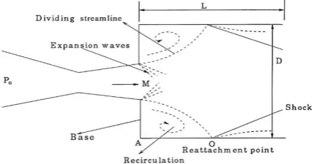
[image:2.595.303.548.140.390.2]Experimental set up has been made to work that projectile base pressures are related to the upstream boundary layer type, thickness, and the location of the transition point. The thickness of the boundary layer just upstream of the corner determines the base pressure for projectiles and a parameter that was the slenderness ratio that is L/D of projectile divided by the Reynolds number based on length to the one-fifth power for turbulent boundary layers to correlate this result. The main features of the suddenly expanded flow field are illustrated in figure 1.
Figure 1:A view of the Flow Field with Sudden Expansion
EXPERIMENTAL SETUP
Figure 2 demonstrates the setup used for the experiments in the present study, as discussed in Ref. [1]. The experimental setup used during the wind tunnel tests comprises of the primary storage tank of air, where the air stored at fifteen bar from an air-cooled air compressor of 25 HP. The air from the atmosphere was passed through the heater and drier to remove the moisture content of the air and then later the air is passed through the filter to separate the contaminations present as impurities are removed. The air from the storage tank was passed through the mixing length, gate valve, and the regulatory pressure valve. Now the air is passed through the piping network into the settling chamber where the air is passed through the wire mesh to eliminate the flow angularity. After all these processes the flow is passed through the nozzle and exhausted into a suddenly expanded duct where all the measurements were done with and without control. For measuring the base pressure as well as the wall pressures of the initial ten taps, the pressure transducer was used, which can measure the pressure in the range from 0 to 15 bar. Takes two-hundred and fifty samples per second and display the average reading of the base pressure as well as the wall pressure on the monitor of the integrated desktop PC. In view of the high sampling rate, it ensures that we do not miss any information about the flow. For the measurements of the wall pressure for the remaining points, the multi-tube
reattached with the duct wall at a distance around 3D. Then from this point of the reattachment, the boundary layer will grow, and the flow recovery will take place, and a smooth increase in the wall pressure is expected until it attains the atmospheric pressure value. Figure 3 shows the duct and location of setup.
Figure 2: Experimental Setup [1]
(a) (b)
Figure 3. A view of the complete setup (a) Duct with pressure tabs and (b) Open Wind-tunnel setup
RESULTS AND DISCUSSION
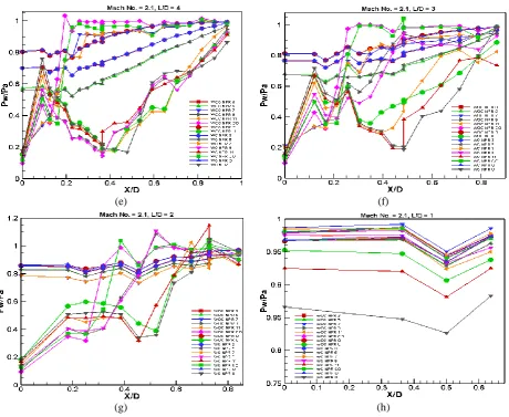
The measured values of the base pressure, as well as the wall pressure, were non-dimensionalized by dividing them with the ambient atmospheric pressure. The wall results for area ratio 4.84 are plotted with respect to the duct length for all the expansion level (i.e., NPR) and non-dimensional duct length are presented in Figs. 4, for Mach number 2.1. The area ratio 4.84 is the case of slightly increased relief for the expanding flow when we compare then with the lower area ratios, namely 2.56, and 3.24. Since the location of the microjets (i.e., the PCD) as the control mechanism was fixed hence due to the increase in the area ratio, the microjets have further shifted away from the base and tend to go near the main jet.
[image:2.595.61.280.201.316.2]International Journal of Innovative Technology and Exploring Engineering (IJITEE) ISSN: 2278-3075, Volume-8, Issue- 9S2, July 2019
are seen for the NPRs very closed to the perfect expansion or under expansion in the presence of the favorable pressure gradient. Within the initial duct length of twenty percent, there is a sudden jump in the wall pressure, which is twenty percent more than the ambient pressure. At L/D = 10 and M = 2.1, the control results in a marginal increase of the wall pressure for most of the NPRs at higher NPRs, and the control effectiveness is only marginal. The trend which was seen at NPR 3 at lower Mach numbers this trend continues at Mach 2.1 for NPR from 3 to 7, as discussed above (Figs. 4 (a)).
Fig. 4 (b) presents the similar wall pressure results for L/D = 8 as was observed in the previous figure with the exception that the wall pressure magnitude has increased considerably because of reduced duct length and flow has become smooth. The reason for this trend is that the reduced duct length will influence the flow field in the duct. The magnitude of the wall pressure is further decreased at lower NPRs. Also, it is seen that the oscillations are further reduced due to the influence of the backpressure.
Figs. 4 ((c) to (d)) represent the wall pressure results for L/D = 6 and 5 with the exception that due the reduction in the duct length there is further reduction in oscillations in the wall pressure flow field due to the influence of the backpressure and the peak pressure values are far less than that those were present at higher L/D ratios namely (L/D = 10 and 8 (Figs. 4 ((a) to (b))). The oscillations in the wall pressure are noticed only for NPR's 9 and 11 which are very closed to cases when the jets are ideally expanded. It is also seen that the flow field has become more smooth in the duct and wall pressure values with and without control are identical in the case of L/D = 5. This trend continues until L/D = 4, and 3 (Figs. 4 ((e) to (f)), then later for lower L/D’s like L/D = 2 and 1 (Figs. 4 ((g) to (h)), it is evident that L/D =1 length is not sufficient for the flow to remain attached with the duct wall and the results for these L/D’s may be ignored and should not be taken into account. Even at L/D = 2, the flow is attached conditionally with the wall is for NPR greater than 7. For remaining NPRs, the flow is detached with the duct. Safely we can say that the flow remains attached for all the NPRs for the present study at L/D = 3.
(a) (b)
(e) (f)
[image:4.595.70.531.46.423.2](g) (h)
Figure 4. Development of the Flow in the Duct
CONCLUSIONS
Based on the above results and discussion, we can draw the following conclusions:
One of the significant problem encounter while using the control the flow field get disturbed, and it is mandatory on the part of the researcher to ensure that the flow field in the duct is not adversely influenced.
From the results, it is being demonstrated; it is possible to control the base pressure as well as the wall pressure flow field without introducing any oscillations to the flow field.
At L/D = 10 and M = 2.1, the control results in a marginal increase of the wall pressure for most of the NPRs. At higher NPRs, the control effectiveness is only marginal.
With the reduction in the duct length, the flow oscillations in the wall-flow field are diminishing. It is evident from the results that L/D =1 length is
Safely we can say that the flow remains attached for all the NPRs for the present study when the duct length is L/D = 3.
ACKNOWLEDGMENT
The authors would like to acknowledge the Bridging Insentif Grant FASA 1/2019 (304.PAERO.6316572) and the RUI grant (RUI 1001/PAERO/8014035) provided by the Research Creativity and Management Office, Universiti Saint Malaysia to support this research.
REFERENCES
1. S. A. Khan and E. Rathakrishnan, Int. J. Turbo Jet Engines, 19, 119–126, (2002).
2. S. A. Khan and E. Rathakrishnan, Int. J. Turbo Jet Engines, 20, 63–82, (2003).
3. S. A. Khan and E. Rathakrishnan, Int. J. Turbo Jet Engines, 21, 233–254, (2004).
4. S. A. Khan and E. Rathakrishnan, Int. J. Turbo Jet Engines, 21, 255–278, (2004).
International Journal of Innovative Technology and Exploring Engineering (IJITEE) ISSN: 2278-3075, Volume-8, Issue- 9S2, July 2019
8. S. Rehman and S. A. Khan, Aircr. Eng. Aerosp. Technol., 80, 158–164, (2008).
9. A. Ali, A. Neely, J. Young, B. Blake, and J. Y. Lim, “Numerical Simulation of Fluidic Modulation of Nozzle Thrust,” in 17th Australasian Fluid Mechanics Conference, 2010, no. December, pp. 5–8.
10. A. Schwarz, J. Janicka, F. Bake, and N. Kings, Combustion Noise. (2009).
11. O. J. Shariatzadeh, A. Abrishamkar, and A. J. Jafari, J. Clean Energy Technol., 3, 220–225, (2015).
12. S. A. Khan and A. Aabid, Int. J. Mech. Prod. Eng. Res. Dev., 8, 1147–1158, (2018).
13. A. Aabid, N. M. Mazlan, M. A. Ismail, N. Akhtar, and S. A. Khan, Int. J. Eng. Adv. Technol., 8, 457–462, (2019).
14. S. A. Khan, A. Aabid, and C. A. Saleel, Int. J. Mech. Mechatronics Eng. IJMME-IJENS, 19, 70–82, (2019).
15. A. Khan, A. Aabid, and S. A. Khan, Int. J. Eng. Technol., 7, 232– 235, (2018).
16. A. G. M. Fharukh, A. A. Alrobaian, A. Aabid, and S. A. Khan, Int. J. Mech. Prod. Eng. Res. Dev., 8, 373–382, (2018).
17. K. A. Pathan, S. A. Khan, and P. S. Dabeer, “CFD Analysis of Effect of Area Ratio on Suddenly Expanded Flows,” in 2nd International Conference for Convergence in Technology (I2CT) CFD, 2017, pp. 1192–1198.
18. K. A. Pathan, S. A. Khan, and P. S. Dabeer, “CFD Analysis of Effect of Flow and Geometry Parameters on Thrust Force Created by Flow from Nozzle,” in 2nd International Conference for Convergence in Technology (I2CT) CFD, 2017, pp. 1121–1125. 19. K. A. Pathan, P. S. Dabeer, and S. A. Khan, Int. Rev. Aerosp.
Eng., 11, 162-169, (2018).
20. K. A. Pathan, S. A. Khan, and P. S. Dabeer, “CFD Analysis of Effect of Mach number , Area Ratio and Nozzle Pressure Ratio on Velocity for Suddenly Expanded Flows,” in 2nd International Conference for Convergence in Technology (I2CT) CFD, 2017, pp. 1104–1110.
21. K. Ahmed, P. S. Dabeer, and S. Afghan, Case Stud. Therm. Eng.,
12, 696–700, (2018).
22. K. A. Pathan, “CFD Analysis of Effect of Area Ratio on Suddenly Expanded Flows,” in 2nd International Conference for Convergence in Technology (I2CT), 2017, pp. 1–7.
23. S. A. Khan, A. Aabid, F. A. G. M, A. A. Al-Robaian, and A. S. Alsagri, CFD Lett., 11, 61–71, (2019).
24. S. A. Khan, A. Aabid, and A. S. C, Int. J. Mech. Mechatronics Eng. IJMME-IJENS, 19, 170–177, (2019).
25. S. A. Khan, A. Aabid, I. Mokashi, A. A. Al-Robaian, and A. S. Alsagri, CFD Lett., 11, 80–97, (2019).