International Journal of Innovative Technology and Exploring Engineering (IJITEE) ISSN: 2278-3075, Volume-8 Issue-10, August 2019
Performance Improvement of a Fin-Tube Heat
Exchanger Using Rectangular Winglet as Vortex
Generator
Sachin Gupta, Arvind Gupta, Munish Gupta
Abstract: Heat transfer performance of fin-tube heat exchanger can be augmented by using longitudinal vortex generators. Numerical simulations have been performed in the present work for investigating the effect of punching a rectangular winglet having hole from fin surface, on the heat transfer and flow resistance characteristics in a fin-tube heat exchanger. The concept of punching out a rectangular winglet having hole from the fin-plate surface is being proposed here and studied in two configurations namely, common flow down and common flow up. Comparisons on the basis of heat transfer and flow resistance characteristics have been drawn for all the configurations under consideration using Colburn’s factor (j), friction factor (f) and performance evaluation criterion (PEC) also known as area goodness factor (j/f). Investigations have been performed considering Reynolds number in the range of 1500 to 9000 and angle of attack as 45°. The result clearly indicates that punched out rectangular winglet with hole having common flow down configuration at upstream location as exhibiting the best thermal performance, followed by common flow up at upstream location and, common flow down at downstream location.
Keywords: Rectangular Winglet, Vortex generator, Numerical Investigation, Fin-tube heat exchanger.
Nomenclature
Ac Cross Section Area (m2)
As Surface Area (m2)
Cp Specific heat at constant pressure (J Kg- 1K-1)
Dh Hydraulic Diameter (m)
k Thermal conductivity (W m-1 K-1)
Q Heat Transfer Capacity (W)
ṁ Mass flow rate of air (kg s-1)
u Component of velocity in x-direction (m s-1)
v Component of velocity in y-direction (m s-1)
w Velocity component in z-direction (m s-1)
Re Reynolds number
Nu Nusselt number
Pr Prandtl number
f Friction factor
j Colburn’s factor
Pm Mean Press. for a cross section (Pa)
ΔPm Mean pressure drop (Pa)
Tm Mean temp. for a cross section (K)
Tm,in Mean temperature at inlet cross section (K)
Revised Manuscript Received on August 05, 2019
Sachin Gupta, Department of Mechanical Engineering, YMCA University of Science and Technology, Faridabad, India.
Arvind Gupta, Department of Mechanical Engineering, YMCA University of Science and Technology, Faridabad, India.
Munish Gupta, Department of Mechanical Engineering, Guru Jambheshwar University of Science and Technology, Faridabad, India.
Tm,out Mean temperature at outlet cross section (K)
Tm,wall Mean wall temp. of fin surface (K)
ΔTm Mean temperature difference (K)
Greek Symbols
µ Dynamic Viscosity (Pa.s)
ν Kinematic Viscosity (m2 s-1)
ρ Density (kg m-3) Abbreviations
CFDD Common Flow Down at downstream location CFDU Common Flow Down at upstream location CFUU Common Flow Up at upstream location RWPH Rectangular Winglet Pair with hole
I. INTRODUCTION
Generator
that by using vortex generators on fin surface, there was a considerable improvement in heat transfer. This was in agreement with the findings of [2]. [4] performed numerical simulation and experimentation for a channel flow considering rectangular and delta wings as well as winglet both and concluded that winglets furnished superior heat transfer characteristics. In his study, he also observed that for identical dimensionless parameters, performance of rectangular and delta winglets was same. [5] considered channel flow to compare the performance of winglets and wings and concluded that winglets outperformed wings for heat transfer enhancement.Studies involving numerical investigations have been taken up over the years to examine the effect of different shapes of winglets and to find the best one for a particular application. Earlier studies were focused on rectangular and delta winglet but [6] simulated numerically and suggested three novel types of winglets as angle rectangular winglet (ARW), curved angle rectangular winglet (CARW) and rectangular trapezoidal winglet (RTW). They reported that for small attack angle, CARW as VG outperforms the other two types of winglet. [7] made experimental investigations and proposed two configurations for winglets known as common flow down (CFD) and common flow up (CFU). [8] performed numerical investigations for both the aforementioned configurations, that is CFU and CFD for rectangular as well as delta winglet and reported that better results are realized using rectangular winglet as compared to the latter in terms of superior heat transfer augmentation. The present work is the first to study the effects of punching out a rectangular winglet with hole, on the heat transfer and flow resistance characteristics in a fin-tube heat exchanger. Rectangular winglet pair having hole has been punched out in two configurations namely Common Flow Down and Common Flow Up. Numerical simulations have been performed using SST k-ω turbulence model which has a demonstrated capability of capturing flow separation in a superior way than k-ε turbulence model. Heat transfer and flow resistance characteristics have been compared for all the cases using Colburn’s factor (j), friction factor (f) and performance evaluation criterion (PEC) also known as area goodness factor (j/f). Investigations have been performed considering the Reynolds number in the range of 1500 to 9000 and angle of attack as 45°.II. MODEL DESCRIPTION A. Physical Model
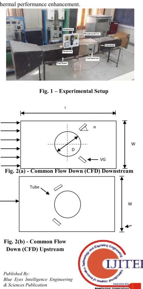
In the present investigation, experiments were performed on a fin-and-tube heat exchanger installed in a wind tunnel test rig. Fig. 1 shows experimental setup with test prototype. The test model has been made up of 25 parallel aluminum fin plates having dimensions as 300×200 mm2 and fin pitch as 24 mm. A circular tube made up of copper with outer diameter as 52 mm and effective length as 300 mm has been fitted through the center of the series of parallel aluminium fin plates. In addition to circulating hot water inside the
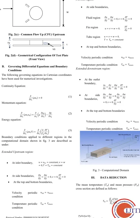
copper tube, an electric heater element has been used for heat generation and kept inside the copper tube. Fin plate number 13 with 3 mm thickness at middle has been chosen for the experimentation work among all the fin plates and fitted with winglets. Rectangular winglet with circular hole at center was the VG under consideration as represented in fig. 2(d). Diameter of tube (D), length of fin-plate (L), width of fin-plate (W), thickness of fin-plate (t) and fin pitch (Fp),
respectively are 52 mm, 300 mm, 200 mm, 3 mm and 24 mm. Longitudinally and transversally, VG has been positioned at 0.5D from the center of the plate. Angle of attack (α), length (Lg), height (Hg) and thickness (tg) of VG
[image:2.595.308.554.340.836.2]is equal to 45°, 18 mm, 12 mm and 3 mm respectively. Longitudinal (x) and transverse position (y) of hole have been taken as 9 mm and 6 mm, respectively. RWPH was attached in both the configurations viz., CFU and CFD at upstream as well as downstream location. Size of VGs, also represented by a measure of aspect ratio has been taken as 1.33 and positions of winglet have been taken as suggested by [9]. As reported by [10] the diameter of the hole has been considered as 4mm. Reynolds number was varied from 1500 to 9000 and angle of attack was taken as 45° for optimum thermal performance enhancement.
Fig. 1 – Experimental Setup
Fig. 2(a) - Common Flow Down (CFD) Downstream
Fig. 2(b) - Common Flow Down (CFD) Upstream L
W
VG D
D
α
Air Flow W
International Journal of Innovative Technology and Exploring Engineering (IJITEE) ISSN: 2278-3075, Volume-8 Issue-10, August 2019
Fig. 2(c) - Common Flow Up (CFU) Upstream
Fig. 2(d) - Geometrical Configuration Of Test Plate (Front View)
B. Governing Differential Equations and Boundary Conditions
The following governing equations in Cartesian coordinates have been used for numerical investigations.
Continuity Equation:
(1)
Momentum equation:
(2)
Energy equation:
(3) Boundary conditions applied to different regions in the computational domain shown in fig. 3 are described as under:
Extended Upstream region:
At inlet boundary,
At side boundaries,
At the top and bottom boundaries,
Velocity periodic condition
Temperature periodic condition
Fin coil region:
At side boundaries,
Fluid region
Fin region
Tube region
At top and bottom boundaries,
Velocity periodic condition Temperature periodic condition
Extended downstream region:
At the outlet boundary,
At side boundaries,
At the top and bottom boundaries
[image:3.595.41.528.58.815.2]Velocity periodic condition Temperature periodic condition
Fig. 3 - Computational Domain III. DATA REDUCTION
The mean temperature (Tm) and mean pressure (Pm) for a
cross section are defined as follows:
(4) t
Fp
VG Plate Fin
Generator
(5)
represents the total heat transfer rate and denotes
temperature difference.
(6)
(7)
Heat transfer coefficient due to convection becomes
(8)
where, is mass flow rate of working fluid, is the fluid temperature at outlet, is the fluid temperature at inlet, is the wall temperature. Specific heat capacity of working fluid is represented by and denotes the total surface area of heat transfer.
The hydraulic diameter ( ) is given by,
(9)
The kinematic viscosity ( ) is given by,
(10)
The hydraulic diameter-based Reynolds number ( ) is given by
(11)
In the above equations, , and denote the air inlet velocity, cross-sectional area of fluid flow and perimeter of wetted surface, respectively. and are dynamic viscosity and density of air respectively.
The Nusselt number ( ) is defined by,
(12)
The Prandtl number ( ) is defined by,
(13)
Darcy Friction factor ( ) which determines the friction characteristics is defined by,
(14)
Heat transfer capacity represented by Colburn’s factor ( ) is defined by,
(15)
Here, and denote the pressure drop between inlet and outlet section of the test section and length of plate along the direction of flow, respectively. Performance evaluation criterion (PEC) mentioned below has been used for estimating the combined effect of thermal performance and pressure drop or flow resistance characteristics of the fin-and-tube heat exchanger.
(16)
IV. NUMERICAL SOLUTION
A. Grid Discretization
A simple cuboidal domain was defined in order to replicate the flow taking place inside a wind tunnel with unequal domain extensions in order to avoid the effect of reversed flow, as encountered by the solver and widely prescribed in literature. Our domain was extended by 45 times the fin pitch (45Fp) towards outlet and 7.5 times the fin pitch
(7.5Fp) towards inlet..
Fig. 4 – Representation Of Multizone Method For Meshed Plate And Winglet
Fig. 4 shows how multizone method has been used to create blocks on the fin-plate and divide it into two zones of structured and unstructured elements. While face sizing functions were implemented on the plate and tube surface for generating mesh of very fine resolution, concept of body of influence was employed for defining preferential element sizing on part of the domain in vicinity of the fin-plate and tube.
B. Grid Dependence Study and Experimental Validation
International Journal of Innovative Technology and Exploring Engineering (IJITEE) ISSN: 2278-3075, Volume-8 Issue-10, August 2019
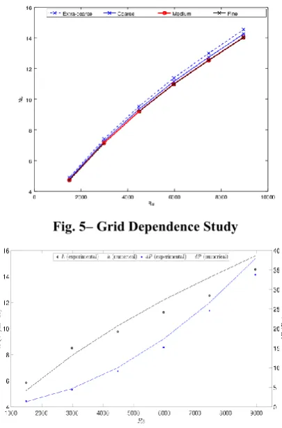
[image:5.595.64.267.150.458.2]whereas the error reduced to an insignificant percentage of 0.014% between medium and fine grids. In order to save on computational resources and allied costs without compromising on accuracy of results, the medium grid was chosen for our simulations. Results of grid dependence shown in fig. 5 are for CFDD case but a similar study was performed for the other cases.
Fig. 5– Grid Dependence Study
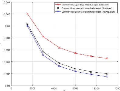
Fig. 6– Experimental Validation
Fig. 6 shows a comparison of convective heat transfer coefficient (h) and pressure drop (dP) values obtained from numerical simulations and experimentation. Results of experimental validation shown in fig. 6 are for CFDD case because of experimentation being performed on the same case.
V. RESULTS AND DISCUSSION
Objective of this work is to find the optimum configuration of punched out RWPH from among the considered configurations. Comments on overall performance of investigated cases have been made on the basis of area goodness factor, which is a ratio of Colburn’s factor and Friction factor (j/f).
A. Selection of optimum configuration
Effect of punching the winglets out of fin-plate surface will now be discussed. Fig. 7a and fig. 7b show variations of pressure drop and Colburn’s factor with Reynold’s number, for punched cases. Fig. 8 portrays contours of pressure for all cases under consideration from both top and bottom view at an inlet flow velocity of 5 m/s. On comparing all the punched cases, we may say that effect of stagnation zone on
pressure drop due to hinderance caused by winglet in the path of flow is less significant in punched-out cases. This is primarily because of the fact that presence of a hole on the plate before winglet acts as a vent which provides an alternate path for air to flow towards the outlet. The second factor that plays a major role in evaluating pressure drop across the fin-plate is formation of recirculation zone behind winglet and tube. When seen from top view, we may notice that all the punched cases have a smaller winglet-dominated recirculation zone. Because of the creation of low-pressure zone of an appreciable size at the back of tube, fluid would always have a tendency to fill in the void if given an opportunity. Another important factor is to consider the flow phenomena taking place near the lower face of plate because of venting. The contours showing bottom view of the fin-plate portray how there is addition of a minor low-pressure region at one of the edges of the hole. An interesting phenomenon taking place here is in case of CFDU configuration. Orientation of the winglet and hole in this case is such that venting promotes fluid to directly hit the tube on its side. The low-pressure zone on the lower face due to hole happens to get formed at very close proximity to the low-pressure zone of tube on its side which further promotes coalescence. This becomes a dominating factor in the punched CFDU configuration.
Fig. 7 – (a) Variation of Pressure drop with Reynold’s number
Fig. 7 – (b) Variation of Colburn’s factor with Reynold’s number for all investigated cases
[image:5.595.325.528.390.523.2] [image:5.595.317.525.560.676.2]Generator
consideration from which, inferences regarding thermal performance of the heat exchanger could be made. Employing the concept of punched-out winglets from plate surface shows the maximum effect in CFDU configuration. In order to understand the reasons behind these results, temperature contours shown in fig. 9 may be referred to. Contours of CFUU show that winglet dominated recirculation zone formed in case of punched-out winglet is significantly smaller. Due to high velocity air streams, heat transfer characteristics improve at the vicinity of the tube in addition to its wake region. Due to the winglet facing away from tube and being located downstream, high velocity air streams turn more towards the back of the tube in punched-out case. This creates a very small region of higher temperature being formed right behind the winglet, as can be seen in fig. 9. The same attributes to a minor reduction in thermal performance in punched-out case of CFDD configuration. Along aforementioned lines of reasoning, tube-dominated recirculation zone shows lower temperature values in punched-out case of CFDU configuration and this accounts for a minor enhancement in thermal performance. [image:6.595.321.517.272.425.2]Fig. 8 – Pressure contours for all investigated cases from top and bottom view of fin-plate at inlet velocity of 5 m/s
Fig. 9 – Temperature contours for all investigated cases at inlet velocity of 5 m/s
Fig. 10(a) shows a plot of friction factor (f) against Reynold’s number (Re). Friction factor is directly proportional to pressure drop and inversely proportional to the square of velocity, hence the shape of indicated curves. Due to the nature of proportional relationship, the trend of friction factor is same as that of pressure drop, shown in fig. 7a. The punched-out case of CFDD configuration exhibits the best performance, when talking in terms of overall pressure drop due to maximum drop in friction factor. Fig. 10b shows a variation of convective heat transfer coefficient (h) with Re. Trend exhibited by these curves is similar to that shown by Colburn’s factor (fig. 7b) because of the direct proportionality of both with Nusselt number.
Fig. 10 – (a) Variation of friction factor with Reynold’s number and
Fig. 10 – (b) Variation of convective heat transfer coefficient with Reynold’s number for all investigated
[image:6.595.49.265.341.458.2]cases
Fig. 11– Variation of performance evaluation criterion with Reynold’s number for all investigated cases Area goodness factor being considered as the scale for performance evaluation in our study provides the best indication of performance comparison between punched cases. The plot of variation of PEC with Re shown in fig. 11 considers the cumulative effect of Colburn’s factor and friction factor. Although there
[image:6.595.316.517.484.641.2] [image:6.595.47.268.503.568.2]International Journal of Innovative Technology and Exploring Engineering (IJITEE) ISSN: 2278-3075, Volume-8 Issue-10, August 2019
punched case of CFDU configuration, the factor of increment in pressure drop dominates and thus a reduction in PEC is seen in this configuration. It may thus be concluded that punched out winglet having CFDU configuration has best thermohydraulic performance from among the considered configurations.
VI. CONCLUSION
The concept of punching out a winglet being used as vortex generator in a fin-tube heat exchanger has been discussed in the present work. Critical comparisons have been drawn between all the configurations under consideration and the effect of each on thermohydraulic performance of the heat exchanger has been studied. The numerical modeling technique employed in our work pointed towards common flow down at upstream location as exhibiting the best thermal performance, followed by common flow up at upstream location and, common flow down at downstream location. On the other hand, plate-punching proved to be advantageous in upstream location when considering thermal characteristics The cumulative effect of thermal characteristics and pressure drop was seen with the help of area goodness factor, stated as performance evaluation criterion above. It can thus be concluded that punched winglets with hole having common flow down orientation at upstream location provide maximum enhancement in overall thermohydraulic performance, and can be especially recommended for use in real life applications.
ACKNOWLEDGEMENT
The authors gratefully acknowledge YMCA University of Science & Technology, Faridabad (India) for financially supporting this research work under grant number R&DGU/2016/01.
REFERENCES
1. A. M. Jacobi and R. K. Shah, “Heat transfer surface enhancement through the use of longitudinal vortices: A review of recent progress,” Exp. Therm. Fluid Sci., vol. 11, no. 3, pp. 295–309, 1995.
2. G. Biswas, N. K. Mitra, and M. Fiebig, “Heat transfer enhancement in fin-tube heat exchangers by winglet type vortex generators,” Int. J. Heat Mass Transf., vol. 37, no. 2, pp. 283–291, 1994.
3. A. Valencia, M. Fiebig, and N. K. Mitra, “Heat Transfer Enhancement by Longitudinal Vortices in a Fin-Tube Heat Exchanger Element With Flat Tubes,” J. Heat Transfer, vol. 118, no. 1, p. 209, 1996.
4. M. Fiebig, “Vortices, generators and heat transfer,” Chem. Eng. Res. Des., vol. 76, no. 2, pp. 108–123, 1998.
5. S. Tiggelbeck, N. K. Mitra, and M. Fiebig, “Comparison of Wing-Type Vortex Generators for Heat Transfer Enhancement in Channel Flows,” J. Heat Transfer, vol. 116, no. 4, p. 880, 2008.
6. B. Lotfi, B. Sundén, and Q. Wang, “An investigation of the thermo-hydraulic performance of the smooth wavy fin-and-elliptical tube heat exchangers utilizing new type vortex generators,” Appl. Energy, vol. 162, pp. 1282–1302, 2016.
7. W. R. PAULEY and J. K. EATON, “Experimental study of the development of longitudinal vortex pairs embedded in a turbulent boundary layer,” AIAA J., vol. 26, no. 7, pp. 816–823, 2008. 8. L. T. Tian, Y. L. He, Y. G. Lei, and W. Q. Tao, “Numerical study of
fluid flow and heat transfer in a flat-plate channel with longitudinal vortex generators by applying field synergy principle analysis,” Int. Commun. Heat Mass Transf., vol. 36, no. 2, pp. 111–120, 2009.
9. S. M. Pesteei, P. M. V. Subbarao, and R. S. Agarwal, “Experimental study of the effect of winglet location on heat transfer enhancement and pressure drop in fin-tube heat exchangers,” Appl. Therm. Eng., vol. 25, no. 11–12, pp. 1684–1696, 2005.
10.G. Zhou and Z. Feng, “International Journal of Thermal Sciences Experimental investigations of heat transfer enhancement by plane and curved winglet type vortex generators with punched holes,” Int. J. Therm. Sci., vol. 78, pp. 26–35, 2014.
AUTHORS PROFILE
Sachin Gupta:
Mr. Sachin Gupta is an Assistant Professor in Department of Mechanical & Automation Engineering at Maharaja Agrasen Institute of Technology, New Delhi (India). He is also pursuing PhD from YMCA University of Science & Technology, Faridabad, Haryana (India). He has completed his M.Tech. in Mechanical Engineering from NIT, Kurukshetra. He has a teaching experience of more than 10 Years. He has published several papers in reputed Journals and Conferences.
ArvindGupta:
Dr. Arvind Gupta is a Professor in the Department of Mechanical Engineering at YMCA University of Science & Technology, Faridabad, Haryana (India). He has completed his PhD in Mechanical Engineering from IIT, Delhi. He has a teaching experience of more than 25 Years. He has published several papers in reputed Journals and Conferences.
MunishGupta: