Retrospective Theses and Dissertations
Iowa State University Capstones, Theses and
Dissertations
1-1-1988
Development of a nerve regeneration conduit
John John Mahendra Kumar
Iowa State University
Follow this and additional works at:
https://lib.dr.iastate.edu/rtd
This Thesis is brought to you for free and open access by the Iowa State University Capstones, Theses and Dissertations at Iowa State University Digital Repository. It has been accepted for inclusion in Retrospective Theses and Dissertations by an authorized administrator of Iowa State University Digital Repository. For more information, please contactdigirep@iastate.edu.
Recommended Citation
John Mahendra Kumar, John, "Development of a nerve regeneration conduit" (1988).Retrospective Theses and Dissertations. 18109.
Development of a nerve regeneration conduit
by c
1'
John Mahendra Kumar Daniel
A Thesis Submitted to the
Graduate Faculty in Partial Fulfillment of the Requirements for the Degree of
MASTER OF SCIENCE
Interdepartmental Program: Biomedical Engineering Major: Biomedical Engineering
Signatures have been redacted for privacy
Iowa State University Ames, Iowa
11
TABLE OF CONTENTS
1.
INTRODU CTION
12.
OBJECTIVES
...
33.
LITERATU RE REVIEW
-!3.1.
, ature of the Problem 43.1.l.
The nervous system 43.1.2.
Types of nerve injuries .6
3.2.
Present Treatment Ylethods7
3.3.
.. erve Grow t h Factor and . europeptides . 143.3.l.
General ..14
3.3.2.
~ erve growth factor 143.3.3.
ources of NGF .15
3.3...l.
Mechanism of action of ~ G F16
3.3.5.
Chemotactic effect ofGF
17
3.3.6.
Other neuronal growth factors 13.3.7.
Commercially available GF 193.4.
Properties of .:V1aterials20
3.4.2. Hydrogels ...
3.4.3. Azo direct dyes
Ill
20
2-1
4. MATERIALS AND METHODS .
26
26
27
27
33
33
36
4.1. Fabrication Considerations . 4.2. Techniques ... .
..t.2.1. Grafting methods . ..t.2.2. ample preparation
4.2.3. Experimental set up and procedure for irradiation -1.2.-L Characterization of grafted silicone rubber tubes
5. RESULTS AND DISCUSSION
3
6 .
7.
8.
9.
5.1. Results . . . 3
5.1.1. Results from t he different techniques used in grafting
HEMA
35.1.2. Radiation initiated polymerization 3
5.1.3. Optical micro copic results -11
5.2. Discussion . . .
CONCLUSION
BIBLIOGRAPHY .
ACKNOWLEDGEMENTS
APPENDIX ... .
41
4-1
52
IV
LIST OF FIGURES
Figure 4.1 : Schematic diagram of experimental set up used for 6°Co
ir-radiation
Figure 5.1: Longitudinal section of a 10 cm long radiation grafted ilasticR
tube (1.9 mm i.d. x 3.1 mm o.d.) showing the
concentra-tion gradient of the dye dispersed in the HE.MA. Dose level
3-!
v
LIST OF TABLES
Table 3.1 : Review of literature on tubular implants for bridging during
nerve regeneration 9
Table 4.1: Various techniques used in grafting 2-HEl\IA onto silicone
rubber
28
Table 5.1: Results obtained from the different methods used in grafting
HEMA onto silicone rubber . . . 39
Table 5.2: Fabrication data for radiation initiated polymerization of
hy-drogel on SilasticR t ubes
40
[image:6.577.81.514.227.488.2]1
1. INTRODUCTION
Until recently, a serious spinal cord injury was always considered to result in
serious loss of function or death, but recent experiments show that nerve tissue
can be transplanted or regenerated, breaks in axons can be jumped electrically and
damaged nerve branches can be reconnected.
Several techniques have been tried to selectively control appropriate neural
regeneration following nerve injury. One such technique is to use a cuff or sleeve
to direct the regeneration, prevent self-reinnervation and permit substantial
cross-reinnervation, particularly of motor axons. Interest continues in the pursuit of a
suitable off-the-shelf prosthesis for supporting nerve regeneration and reconnection.
This work was undertaken to investigate the feasibi lity of developing a
com-posite regeneration tube using current fabrication methods. Several methods were
tried in an attempt to develop a simple. reproducible method of fabrication.
A nerve cuff was designed and fabricated by grafting 2-hydroxyethyl
methacry-late (HEMA) onto a silicone rubber (SilasticR ) tube using a 6
°Co
radiation source.HEMA was chosen because the physical properties of hydrogels closely resemble those of living tissue, and the silicone rubber tube provides mechanical stability. A
suitable hydrogel formulation was chosen to provide the required microstructure for
2
fiber growth follows a concentration gradient of a nerve growth factor or stimulant.
Hence , a technique was developed to lay down a concentration gradient of the dye
(which was used instead of the nerve growth stimulant) in the grafted hydrogel
matrix along the axis of the tube. Also, a special setup was designed to position
a glass mandrel coaxially in the lumen of the silicone rubber tube and hold it
up-right during irradiation. Visual and optical microscopic evaluations were done to
determine the dye concentration in the grafted hydrogel.
The results of this st udy establish that a hydrogel having a controlled
m1-crostructure and a lengthwise distribution of a dye in its matrix can be grafted onto
the inner wall of a silicone rubber tube. This investigation also indicates the
3
2. OBJECTIVES
The objective of this study is to design and develop a 2-hydroxyet hyl
methacry-late (HE}.,L..\ ) coated silicone rubber su bstrate nerve prosthesis which can be used
to support an injured nerve and control the direction and rate of regeneration. The specific objectives include the following:
1. To choo ea suitable formulation for the polymer,
2. To design the struct ure, deterrrline the dimensions and develop a method to make several such conduits of varying cross section, and
3. To develop a method of impregnating the polymer. with a dye or fl uorescent
marker or an element t hat can be determined by X-ray rrlicroprobe analysis,
3. LITERATURE REVIEW
3.1. Nature of t h e Problem
3 .1.1. The nervou s system
The human nervous system consists of an extensive network of several billion
neurons which are capable of receiving, storing and transmitting information. The
neurons have long, thin extensions called axons. Neurons communicate with one
another and with other nonneuronal cells through these axons. The axons are filled
with cytoplasmic fluid which includes mitochondria, microtubules and neurofibrils.
In addition to transmitting electrical signals, the axons also ferry nutrients and other vital substances to and from the cell body. Each neuron has only one axon,
but each axon generally has several branches called collaterals.
The nervous system is separated into two major divisions based on structural
locations: the central nervous system and the peripheral nervous system. The
central ner vous system includes the brain and the spinal cord. The peripheral
nervous system which comes out of the spinal cord is composed of:
1. nerves which connect the distal body regions with the central nervous system.
5
The peripheral nerves a re of 3 types : sensory neurons , which transmit nerve
impulses from sensory receptor sites to the spinal cord; motor neurons, which
inner-vate the skeletal muscles; and autonomic neurons, which innerinner-vate cardiac muscle,
smooth muscle and glands.
Peripheral nerve injuries are usually caused by car or industri al accidents. But
injured peripheral nerves can be made to fun ction again because they are capable
of growing after injury. T he problem the growing neuron s face is t hat they do
not know which way to go when t hey grow back. Each peripheral nerve consists
of several thousand individual nerve fib ers and each of those fibers has its own
protecti ve sheath surrounding it . The sciatic nerve in the leg, which is t he largest
peripheral nerve, is made up of about 175,000 nerve fibers. After a nerve injury
occurs , the growing nerve fibers must be able to cross a gap that usually contains
blood and scar tissue for proper function to be restored.
Peripheral nerves have 3 supporting structures: the epineurium, t he perineurium
and the endoneurium. All t hree play an important role during the nerve repair. Each ner ve fiber is individually wrapped by a thin connective-tissue sheath called
the endoneuri um. The nerve fibers are separated into bundles called fasiculi by
an-other connective-tissue sheath called the perineurium. The epineurium sur ro unds
several fasiculi , blood vessels and lymphatic vessels, all of which con stitute a single nerve.
Each nerve fiber con sis ts of one large axon ( myelinated), or several small axons
(unmyelinated ). The axons are ensheathed by a chain of Sch wann cells distributed
materi-6
als between the neuron cell body and distal axon, and also between the neuron
and chwann cells (Daniller and trauch, 1977). During development, some of
the chwann cells become associated with a ingle axon and by a process know n
as spiralization , surroun d the axon wit h compact layers of plasma membrane, or
myelin. Each Schwann cell forms a myelin sheath for a regular repeating lengt h of
the axon that ends at the node of Ranvier. The integrity of the myelin sheath and
node of Ranvier is essential for normal axonal impulse propagation (Spencer. 1974).
chwann cells associated with unmyelinated fiber enclose many small. naked axons
wi thin their cytoplasmic processes.
There is a thin extracellular coal called the basal lamina. which surrounds the
outer surface of the Schwann cells of a myelinated or unmyelinated fibe r. This fo rms
a continuous t ube t hat sep arates t he nerve fi ber fro m t he surrounding endoneurial connective tissue.
3.1.2. T y p es of n e r ve injuries
The degree of damage to a nef\'e fiber increases in severity "·ith the velocity,
increasing temporal span. and force of the damaging agent (Daniller and trauch. 1977). ~[yelinated nerve fibers are more susceptible to injury as compared to
un-myelinated ones.
elective da mage to Schwan n cells a nd t he myelin sheath may occur during mild injury or indirect compressions. T he damaged myelin is retracted (demyelination),
7
which results in increased slowing of motor conduction. These types of injuries are
classified as first degree nerve injuries.
Another example of this type of Injury 1s termed axonal interruption (also
called axonotmesis). In t his type of injury, axonal continuity is lost , and the distal portion of the axon undergoes dissolution because of the separation of the axon
from the supply of materials from the neuron cell body (Daniller and Strauch, 1977). The myelin collapses around the dying axon and the degenerating material
is removed by phagocytosis. The entire process by which the fiber is removed from
the endoneurial tube is termed Wallerian degeneration (Spencer, 1974). Motor, sensory or autonomic paralysis may be complete. The prognosis is less favorable if
the supporting structures a re also damaged along with the axons. Recovery may
be incomplete and full function may not be restored. Regenerating axons become
misrouted and fail to reach their target organs. This injury, known as neurotmesis, may result from endoneurial disruption, endo- and perineurial injury, or a complete
severance of the nerve trunk (Spencer, 1974).
3.2. Present Treatment Methods
Current surgical techniques used in the repair of peripheral nerve injuries do
not provide satisfactory results and complete restoration of function is difficult to
achieve using these methods. End-to-end anastomosis using microsurgical principles
and ground fasicular sutures, with or without a nerve graft bridging the nerve defects, is the most common procedure being followed by surgeons. (Grabb et al.,
8
also known to be unfavorable (Lundborg, 1975; Terzis and Williams, 1975).
There is a fundamental difference in the suqpcal techniques used in repairing an
artery or bone and an injured nerve fiber. Tissue surgery is used to repair an injured
artery or bone. But in the case of nerve injuries, only one cell is cut when a nerve
fiber is cut. Hence, cellular surgical principles have to be applied to successfully
repair cut nerves. There are several factors that have to be carefully considered
when nerve injuries are surgically repaired. One, damage should not occur to the
nerve fiber when the injured nerve ends are trimmed before reconnection. The nerve
fiber can be frozen and then trimmed with a vibrating blade to avoid damage to
the cell fibers. Two, to keep the interior of the nerve fiber from losing its chemical
and ionic balance, the cut ends should be bathed in solutions that are identical to
the axonal cytoplasm. Three, some kind of support structure has to be provided to
hold the cut ends together. This support or guide is needed to direct the growing
axon.s. They also serve as a reservoir to hold the secretions that ooze from the cut
ends. These secretions, which have NG F in minute quantities, have a trophic effect
on the growing axon s.
Experimentally, it has been shown that nerve defects can heal through bridging
tubular implants of autogenic or synthetic origin (Lundborg and Hansson, 19 O;
Denny-Brown, 1946; ~olander et al., 1982). Details of some of the tubular implants,
Table 3.1: l{eview of lite rature o n tubular implants for bridging during nerve regeneration
Research Group Yann as, l. V.
et al.
( 1985)
Madison , R.
et al.
( 1985)
Munz, M .
et al.
( 1985)
Rat
Animal and ty pe of nerve
Sciati c nerve (Gap of J5
mm)
Rat
Sciatic ne rve (Cap of 5 mm)
Section of the optic nerve was replaced by a
sect ion of the sciatic nerve of rat.
Type of cuff
Silicone tube packed with a protein collagen and a glycosarn.inoglycan
(GAG)
polysaccharide,chondroitin-6-sulfate. These mate rials were cross-linked to form a porous network that was degradable by e nzymes at rates that could be controlled du ring preparation. The silicone tube was not biodegradable.
Nerve guides we re polyme rs o f synthetic poly -
D, L -
lact ates with2%
triethyl citrate added as plasticizer. These guides were lined with either a collagen matrix or a laminin-containing gel.No cuff was used
Comments
The regenerated nervous tissue was healthy, highly vascularized and about
'
20%
of the axon al fibers were surrounded by a fatty myelin sheath produced by Schwann cells that migrated into the tube.A larninin gel matri x lining the nerve guide significantly s peeded up axon al
rege neration in vivo 111
ra t sciatic nerve.
Severed axons of adult ra t retinal ne urons could
regene rate through a n c nti re 20-30 mm peripheral
Table 3. 1: Continued Research
Uroup C hiu , D.'f. ct al.
( 1982)
Animal a nd type of nerve A J cm segment of rat scia tic ne rve was removed.
Molander, II . Adult ra bbit ct al. tibial 11er ve (1983) (Uap - 10
mm)
Longo, F.M .
ct al.
( L 983)
Adu lt ra t sciati c nerve (Gap IO
mm)
Type of cuff
A segment of femoral vein was used lo bridge the nerve gap
Polyglactin tube made
of a polyglactin suture mesh with a pore size
o f O.tl x 0.4 mm a nd a thread dia meter of 140_L20 µrn.
Silicone chamber
Inner diame ter - 1.2 mm Outer dia mete r - 2.0 mm
Comments
llistologic evaluation s howed orderl y growt h of nerve fibers within the lumen o f the vein grafts. They reached the distal stump within 2 mo nths after repair. Nerve conduction studies s howed restoration of conduction with muscle rei 11 ne rvation.
T he polyglaclin tube bridgi ng
a nerve defect gives regeneration as good as conventional ner ve grafting. T he tube i11fluc11ce<l the <lirectiun taken by the axons a nd guided them into the
distal segment.
T he fiuid t ha t accumulates in t he cha mbe r has a trophic effect on nerve regeneration.
...
Table 3.1: Continued llesearch
Group Young, B. L.
et al.
( l 98tJ)
Animal and type of ne rve The nerve to the medial gastrocnemius muscle was crossed wit h that to the lateral gastrocnerni us and solc11s muscles in cats. Also the nerve to the 111c<lial ga.st roc-nerniw; was crossed with that to the sole us 111 uscle in cats.
Mic.lcnbcrg, M.L. 39 year old
a nc.I Caucasian male
Kirschenbaum, S.E. s11ral ne rve in
( I 98u) the rig ht leg
Typ e
of cuff
Gore-tex
(Expanded poly tet ra
n
uoroet hyle ne)Inner diameter = 1 mm lnternodal distance
=
301tm Length 15 mm(was compressed to 5 rnrn for insertion)
Si~e- 4 Swanson-Ducker
Silastic11 ne rve cap
Comments
Neural tissue invasion into the Core-texR matri x does not occur even t hough othe r cell
ty pes invade and a good vascular s uppl y is
provided. Motor
i 1111ervation was excel Jent b ut sensory i 1111ervatiu11 was d epressed.
Table 3.1: Continued Research
Group Muller, 11.
et al. ( 1987)
Rat
Animal and type of nerve
sciatic nerve (Gap 1 Omm)
Type o f cu ff
25 µliter silico ne chamber
( In ner diameter - 1 .8 mm)
Comments
A mixture of laminin , testosterone, ganglioside, and cata lase applied
by multiple injections into the cha mber was shown to advance substantia lly the progress of regeneration in 16 days, as compa red to saline filled chambers.
When sections containing axons 3 mm from the proximal stump were com pa red in experimenta l and control groups, computerized area measurements revealed a n average 2-fold diffe rence for the cross-sectional size of the whole
[image:18.788.117.665.141.478.2]Table :l. I: Continued Research
Group Lundbo rg, C.
ct a.I.
( 1982)
Animal and ty pe of nerve C ross - anasto mosed rat sciatic ne rves (C a p = 6 mm and I 0 rnm). Two arra nge me nts were exarruned after 1 month in situ: A proximal - distal
(PD) system in which both proximal a nd distal stumps were introd uced into the ends of the clia rnbcr, and a. proximal - open (PO ) systc1n in whicli the dista l stump was omitted .
T y pe of cuff
C ylindrical silicone chambe r.
(Inne r diameter - 1.2 mrn , Ou ter dia meter = 2.0 mm )
Comments
Fo r the
6
mm gap, a regene rated nerve exte nded all the waythrough the cha mber in both t he
PD and
PO
systems . !"or the 10 mm gap, a similar regrowth occurred in the PD cha mbe r, whereas in the PO cha mber proxima l regrowt h was pa rtia l o r non-existent....
14
3.3. Nerve Growth Factor and Neur opep t ides
3 .3.1. G e n e r al
euronal growth factors play a key role in the development of the nervous
sys-tem and in neuronal repair mechanisms. When an injured axon starts to regenerate, there is an increased synthesis of proteins in the cell body and an enhanced
trans-port of the newly synthesized materials to the growing axon tip. The extracellular
matrix which consists of Schwann cells and fibroblasts also play an important role in
regeneration. The denervated target organ and the Schwann cells that proliferate in the distal nerve segment start producing increased amounts of nerve growth factors.
Thei r production is triggered by degeneration materials and modulated by contact with the new growing axons. Laminin, which is an extracellular matrix protein,
stimulates neurite outgrowth in vitro and axonal regeneration in vivo (Dekker et al., 1987).
3.3 .2 . Nerve growth factor
erve Growth Factor (NG F) was discovered in 1953 by Levi-Montalcini. She
observed that an implant of mouse sarcoma tissue caused a marked increase in the
size of sympathetic and sensory ganglia in chicken embryos. Further experiments
proved that this effect was due to the nerve growth factor. ~GF was purified in
1960 by Stanley Cohen. It is a 13.25 kD, oligomeric protein complex, consisting of three subunits: alpha(2)-beta-gamma(2). The B-subunit (a dimer of two identical
polypeptide chains of 11 residues, :VIW
=
13.250, pl=
9.3) contains the biological15
polypeptide chain is stabilized by three covalent sulfur-sulfur bridges between units
of the amino acid cysteine at different positions (15- 0. 58- 108, 68- 110) along the
chain. T he a and -y subunits serve to activate, store and protect the XGF molecule.
T he structure of the polypep tide chain of mouse NGF as described by Boyd et
al. (1974) is:
-HrSer-Ser-Thr-His-Pro-\ 'al-Phe-His- i\Iet-Gly-Glu-Phe-Ser-Val-Cys-
Asp-Ser-Val-Ser-Val-Trp-Val-Gly-
Asp-Lys-Thr-Thr-Ala-Thr-Asn-Ile-Lys-Gly-Lys-Glu-Val-Thr-Val-Leu-Ala-Glu-Val-Asn-Ile-
Asn-Asn-Ser-Val-Phe-Arg-Gln-Tyr-Phe-Phe-Glu-Thr- Lys-Cys- Arg-Ala-Ser-Asn-
Pro-Val-Glu-Ser-G
ly-Cys-Arg-Gly-Ile-Asp-5er-Lys-His-Trp-Asn-5er-Tyr-Cys-T hr-ly-Cys-Arg-Gly-Ile-Asp-5er-Lys-His-Trp-Asn-5er-Tyr-Cys-Thr-ly-Cys-Arg-Gly-Ile-Asp-5er-Lys-His-Trp-Asn-5er-Tyr-Cys-Thr-His-ly-Cys-Arg-Gly-Ile-Asp-5er-Lys-His-Trp-Asn-5er-Tyr-Cys-T hr-P he-Val-Lys- Ala-Leu-ly-Cys-Arg-Gly-Ile-Asp-5er-Lys-His-Trp-Asn-5er-Tyr-Cys-T hr-ly-Cys-Arg-Gly-Ile-Asp-5er-Lys-His-Trp-Asn-5er-Tyr-Cys-Thr-Asp-Glu-Lys-G
ln-Ala-Ala-Trp-Arg-Phe-Ile-Arg-Ile-Asn-Thr-Ala-Cys-Val-Cys-
\ial-Leu-5er-Arg-Lys- Ala-Thr-Arg-COOH.
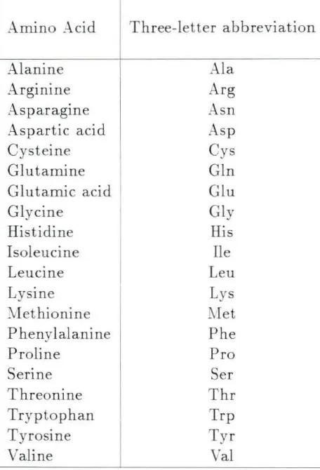
The preceding abbreviations for the amino acids are explained in full in the
appendix. The aggregate formed by the association of the ,B-subunit with the a and
-y subunits is termed 7S NGF. The purified form of ~GF obtained by dissociation
of this aggregate is denoted as 2.55 _ GF . Only the 2.55 ~GF and the
,B-
GFcomponent of the 7S ;.;-GF have biological activity.
3 .3 .3. Sources o f NGF
3.3.3.1. Submax illary g land of the m o use The convoluted tubules (not
the acinar part ) of the male mouse sub maxillary gland produces large amounts of
16
10 times more active than t hat in snake venom.
3.3.3.2 . Mouse sarco m a NGF was first identified in mouse sarcoma - 180
tum or cells.
3.3.3.3. Snake ve nom NGF was isolated second in snake venom, which
contains a high concentration of the enzyme phosphodiesterase. Crotalidae,
Viperi-dae and ElapiViperi-dae are 3 of the poisonous snake families from which _ G F has been
purified (Hogue- Angeletti and Brads haw, 197 ). The most extensively characterized
.:\TGF is the one isolated from cobra venom ( aja naja).
3.3.3.4. Prosta t e gland o f g uinea pig Harper et al. (1979) isolated I GF
in the prostate gland of the guinea pig with levels comparable to t hose in the male
mouse submaxillary gland.
3.3.3.5. Goldfis h brain . GF has also been isolated in the brain of the
goldfish by Benowitz and Greene (1979) . Pheochromocytoma cells (P C12), whi ch
respond to -GF by producing new fibers were used by them in identifying .:--IGF in
goldfish brain.
3.3.4. lVIe cha nis m o f action o f N GF
T he mechanism of action of NG F on neurons and other cell types is still
un-known. Since NGF has multiple actions on most cell types, in any study the steps
of different mechanisms are likely to be found intertwined. P heochromocytoma cells
17
of the current research is focused on t he effect of ~G F on p hospholi pid metabolism
as a possible transducing step in the neurite promoting effect of >J"GF (Dekker et
al. , 1987).
3.3.5. Chemotactic effect of NGF
Charlwood et al. (1972) used mouse sarcoma - 180 containing nerve growth
factor to stimula te nerve fiber growth in the sensory ganglia of chick embryo, which
was cultured in a liquid medium of rat tail collagen. T hey observed greater nerve
fiber outgrowth from the side facing t he source of NGF than from the opposite
end . This effect was not seen when the ganglia were cultured in the absence of
NGF. Since t he concen tration of NGF was greater on the side of the ganglion closer
to t he source, the fibers could have followed this concentration. However, when
the experiment was done with 2 ganglia cultured in the presence of 1 source, they
observed that fiber outgrowth was greater from the side of the more distant ganglion
facing towards the source as compared to the outgrowth from t he side of the nearer
ganglion facing away from the source. From these experiments, they determined
th at t he nerve fiber outgrowth follows the concentration gradient of ~G F rather
t han its concentration. This effect is t hus an example of chemotaxis. Charlwood
et al. (1972) also suggested th at other than influencing the growth of nerve fibers,
>J"GF also may play a key role in directing the nerve fi bers during development and
regeneration.
In 1978, Letourneau used semisolid agar matrices containing concentration
18
chick embryos . He observed a preferential orientation of more than half of the
nerve fiber tips and a greater extension of fibers along GF gradients. He also
observed orientation o f nerve fibers toward the GF source in chambers with ~GF
sources ranging from 25 to 1000 ng/ ml of 8-NGF and from 400 to 5000 ng/ ml of
75-NGF, but saw no orientation when the concent ration of the ~GF source was 15000
ng I ml of {3- G F. Letourneau concluded that this orientation response apparently is
not a concentration-dependent trophic response to NG F . His exp erimental evidence
strengthens the belief that chemotaxis is an important regulatory factor in neuronal
morphogenesis.
Carbonetto et al. (1982) have shown that cultured neuron s become attached
to the hydrogel substrates prepared from HEMA but grow few nerve fibers unless
fibronectin, collagen, or
B-
GF is incorporated into the hydrogel. They also haveshown that there is a direct and selective interaction of the nerve fiber surface with
defined molecules embedded in t he gels.
3.3.6. Othe r neuro na l growth facto rs
~GF was t he only known growth factor for several years. In 1982. Barde et al.
isolated a growth factor from pig brain. Ciliary euronotrophic Factor (CI TF) was
purified in 1984 by Barbin et al. Even though the number of partially characterized
19
3 .3 .7. Commercially available NGF
Some o f the nerve growth factors which are commercially available are
1. 2.5S-Nerve Growth Factor 1
From male mouse submaxillary gland.
11.vV. approx : 26 ,000
2. 7S<'\Terve G rm\·th Factor 1
From male mouse submaxillary gland.
11. W. approx : 140,000
3. 2.5S- GF 2
From mouse submaxillary gland.
Endotoxin tested .
4. 75-.\TGF 2
From mouse submaxillary gland.
Lyophilized from phosphate buffer.
5. l\'erve Growth Factor 2
From Vipera leletina venom.
Lyophilized.
1 IC Biomedicals , Inc., Costa Mesa, California.
20
3 .4. Prop e rties of Materials
3 .4 .1. Silicone rubber
Silicone rubber (polydimethylsiloxane) is one of the best biocompatible
poly-mers for implant applications. :VIedical-grade silicone rubber can be divided into
the heat-vulcanizing variety and the room-temperature-vulcanizing variety (RTV)
(Braley, 1970). The heat-vulcanizing variety of silicone rubber contains a finely
di-vided silica filler with a particle size of about 120 to 300 Angstrom units. This filler adds strength to the silicone rubber and usually, the more filler used. the harder
the rubber is. The RTV silicone rubber is divided into two component RT\' and
one component RTV. The two component RTV rubber (vulcanization requires a
catalyst to be mixed into the base) contains diatomaceous earth particles for filler , ranging in size from 1 to 30 µm. The base is a fluid silicone polymer, mixed with
filler and a cross-linking agent. The cross-linking of the silicone polymer units is
initiated by the catalytic action of the organo-metallic compound, stannous
oc-toate. These cross-linked polymers form the silicone rubber with filler dispersed in the matrix. In the case of the one component RTV, vulcanization is initiated by
absorption of water vapor from the air.
3.4.2. H y droge ls
3.4.2 .1. G e ne ral Hydrogels are cross-linked polymeric networks capable of
absorbing and holding large quantities of water without dissolution of the polymer
network (Bruck, 1972, 1973). They were first used for biological applications in
21
of living tissue more than any other type of synthetic biomaterials (Ratner and
Hoffman , 1976).
Hydrogels can be fabricated by different polymerization techniques or by
con-version of existing polymers. 2-hydroxyethyl methacrylate (HEMA ), cross-lin ked
with ethylene glycol dimethacrylate, is one of the most popular types used for
bi-ological appl ications. The ease with which the combination of cross-linking and simultaneous solution polymerization occurs is an important advantage of the
hy-droxyethyl methacrylate esters. Details of the \'arious techniques of synthesis and
the resulting properties of hydrogels have been published by Refojo and Yasuda
(1965), \Vichterle (1971) . and Ratner and Hoffman (1976).
There are several major ad vantages of hyd rogels according to Ratner and
Hoff-man (1976). One, the expanded nature of the gel network facilitates the removal
of unwanted initiator molecules, solvent molecules and other extraneous materials
from the gel network before the hydrogel is used in vivo. Two, the physical
irri-tation at tissue- polymer interfaces is minimized because of the soft and rubbery consistency of hydrogels. Three. the in l'ivo performance of hydrogels is greatly
improved because the gel matrix allows mall molecules and metabolites to diffuse
across it ( Levowitz et al., 196 ). Four, hydrogels are chemically stable and will not
easily cause dissolution of the poly mer. F'ivc, the low interfacial free energy and work of adhesion between the hyd rogel surface and an aqueous surface (Andrade,
1973) reduces the tendency of proteins in body fluids to adsorb onto the gel surface
(Hoffman, 1974). Six, the ease with which hydrogels can be made into a wide range
22
various applications.
3.4.2.2. C he mical properties and grafting methods Hydrogels are
chemically stable d ue to the three-dimensional structure of the polymeric chains
and the strong C-C bonds. The principal monomer used in the formation of
hy-drophilic gels is HE:VIA,
which is polymerized by conventional free radical methods in the presence of small
amounts of cross-linking agents such as ethylene glycol dimethacrylate,
By varymg the solvent content during polymerization, the amount of water
taken up by the hydrogels made from the monomer and cross- linker described above
can range from 353 to 903 of their weight. If polymerization is carried out in the absence of sol vents for t he polymer , a hard and brittle polymer is obtained.
However , polymerization in a medium t hat contains a nonsolvent for the polymer
results in precipitation of polymer and either an opaque gel or a microporous sponge
wit h a range of pore sizes depending upon the polymerization condit ions is obtained
(Greer and Knoll , 1980).
T he biggest disadvantage of using hydrogels in biomedical applications is t hat
the high water content of hydrogels makes them mechanically weak. This
23
a substrate (Ratner and Hoffman , 1974) or impregnating a substance with the
hy-drogel (Predecki , 197-1).
By
using t hese methods, the biocompatible properties ofthe hydrogel can be combined with the mechanical properties of the substrate.
The grafting technique has several ad vantages over other method s of
incorpo-rating HE:\L.\ onto a substrate polymer. First, successive graftings using different
formulations can be used to fabricate complex surfaces. Second , variations in solvent
and other grafting parameters can be utilized to make the hydrogel graft onto the
surface, penetrate into the substrate, or disperse uniformly throughout a
hydropho-bic matrix. Third, there is no need for adding initiators to initiate polymerization,
thereby eliminating one potential sou rce of contamination in the final product.
T he disadvantages of graft polymerization are polymer degradation ,
cross-linking an d formation of unwanted chemical species.
V
sing low dose levels canminimize the problems caused by degradation and cross-linking. Elimination of
un-wanted functional groups can be achieved by excluding oxygen and reactive solvents
from the grafting environment .
3.4.2.3. Immobilization and e ntrapme nt of biologically active molecules on and w it hin hy drogels Thre are several ad vantages in using
hy-drogels as a base material for "biologically active" biomaterials. One, the rate at which small molecules (drugs, enzymes) diffuse through the gel matrix can be
controlled by co-polymerizing the hydrogel in varying ratios with other monomers.
T wo, the tendency to interact with t he biologically active molecules is much less
24
reaction when left in contact with blood. Four, the large number of polar reactive
sites on the hydrogels enables the biologically active molecules to be immobilized
by simple chemical techniques (Ratner and Hoffman , 1976).
The biologically active molecules can be immobilized \Vi thin the hydrogels
ei-ther permanently or temporarily. Active biomolecules can be easily entrapped in
the matrix of hydrogels which are formed by the solution polymerization method.
In order to immobilize a biomolecule, the pore size or average interchain distance of t he gel should be smaller than the size of the active molecule. Gutcho (as cited by
Ratner and Hoffman, 1976) reports that a pore size of 35 Angstrom units or smaller should be suitable for retaining most entrapped enzymes. Controlled drug
deliv-ery devices can be fabricated if the hydrogel is designed to release the entrapped
biomolecule at a preset rate. Different methods have also been developed for the
covalent immobilization of active molecules to hydrogel surfaces.
3.4.3. Azo direct dyes
Azo direct dye consists of at least two ring structures connected by the azo
chromaphore (-N = N-). The ring structure is made up of sulphonic acid solubilizing
groups and hydroxyl groups.
The anionic charges of the hydroxyl groups on the dye molecules are repelled by
similar charges on the hydroxyl groups of the hydrogel at neutral pH levels. Placing
203 (wt dye / wt hydrogel sample) of the dye and the hydrogel in a boiling salt
25
the la ttice and are permanently secured to the gels by hydrogen bonds and Van der Waals forces (Eckstein and Pinchuk, 1982).
This dye technique is used to determine the presence and uniformity of the
hydrogel graft when hydrogel is grafted onto polymeric substrates by radiation
methods. Any dye that remains fixed to the sample surface indicates a grafted
surface. According to the Beer-Lambert law, the depth of color of the dyed hydrogel
26
4. MATERIALS AND METHODS
4.1. Fabrication Considerations
T he development of a composite nerve regeneration tube ·with hydrogel
impreg-nated into or bonded onto silicone rubber substrates requires approaching the
prob-lem from several viewpoints: fabrication considerations, chemical and
rnicrostruc-tural properties considerations, design considerations, and biological variability
con-siderations.
Based on previous n erve injury treatment methods, a tubular configuration was
chosen. The HEMA which contained the Azo direct dye (Sirius Supra Yellow GD
167, Verona Dyestuff Div., Mobay Chemical Corp., )l"J) was grafted ont o the inner
wall of t he silicone rubber SilasticR tube which provided the mechanical ~trength to
the structure. The Azo direct dye was used to provide a visualization of a chemical gradient instead of nerve growth factor molecules.
The formulation for the HEMA to be used was dictated by the ' pore' size
of the HEMA matrix because this is importan t in immobilizing the biologically active molecules. The composition chosen was (in volume percent): 203 HEMA
(Polysciences Inc., Lot 2-2405), 393 methanol (1003 pure), 2.03 EGDM (Monomer
27
/ 503 H2
0
co-solvent). The microvoid size is<
lµm for this formulation (Knoll,1980).
The HEJ\IA was radiation grafted (dose level = 0.25, 0.5 or 1.0 t-.Irad) onto the walls of 1.98 mm i.d. silicone rubber tubes (Dow Corning, SilasticR ~ Iedical Grade
Tubing, Lot HH055153, 1.9 mm inside diameter x 3.18 mm outside diameter). The
silicone rubber tubes were placed in a specially designed glass support tube which held the silicone rubber tube upright during radiation. A glass capillary tube of 1.39
mm i.d. was placed coaxially within the silicone rubber tu be to provide a hydrogel
layer on the inner wall of the silicone rubber tube. By using various sizes of these
capillary tubes, the lumen diameter can be easily altered to accommodate different nerve sizes.
4 .2. T echniques
4 .2 .1. G ra fting m ethods
Several methods have been developed for grafting hydrogels onto silicone rub-ber. In this study, several of these methods were tried in order to determine the
technique best suited for this purpose.
The free radical initiated polymerization reaction method (Pinchuk and
Eck-stein, 1981 ), the interpenetrating polymer networks method (Predecki, 1974), the
dip-coat method and the radiation grafting method developed by Ratner and Hoff-man (1974) were applied to graft HEl\IA onto the walls of the silicone rubber sam-ples.
Table ·I. I: Various t echniques use<l in grafting II EMA onto sili cu11e rubber
A uthor(s) and date Pi 11ch11 k
;rnd Eckstei n ( 1981)
Technique used
Free rncl i cal i 11 i ti atecl poly mcri :.mtio11 read ion
Procedure
(i) Initiator solution
[G g (N ll4)iS2011 in 100 ml distilled watt'r] ( Fi sher Sci . Co., Lot 743791)
(ii) Co-initiator solution
i t 2 g Na2S20s in 100 ml of distilled wate r! ( Fisher Sci . Co., Lot 745412)
(iii ) A mixture o f monomer and cross-linker consis ting of 50 ml
HEMA
( Polysciences Inc., Lot 64622)and I ml tet raethylene glycol dimeth-acrylate (TEG
DMA )
( J>olysciences 1 nc. , Lot 4-1686) and 17 ml of ethy lene glycol (Polysciences I nc. , Lot 2,1685). Al l three solutio ns we re purged with 2 gas separately for 30 minutes.
8 rnl o f 11 l~ M A-TEC DM A-e th ylene
glycol mi xture was loaded in a 10 ml polyethy l<'nc sy ringe. I ml of initi a tor and I 1111 o f co initiator solutions were a dded separately to t he mi xture a nd agitated . T his nrixt 11rc was injected into t he insid e of previously washed a11d dried Silastic/? tubi11g, J .98 mm i.d, and 100 rnm lu ng ( Dow Cuming, Lot llll 055153),
usi ng a lo11g stai11less s teel needle.
Comments
Th<' ll RMA - T ECDMA . ethylene glycol ratio (50: I :27) was different from the
ratio use<l by J>inch uk and Eckstein (50: 1:17).
lt eaction times were
I 00 120 minutes, whereas Pinchuk and 8ckstein reported 15 minutes fo r pol yme ri zatio n.
[image:34.785.94.685.88.505.2]Table 4. l: Continued A uthu r(s)
a n<l <late
Predecki , P.
( la74)
Technique used
Oiff11sion bo nding or surface im pregna tion of silicone r ubber with ll P.M A.
1 nterpenct ra ting Polyme r Net wo rks
(IPN)
P rocedure
ln a nothe r set of experiments, 0.0 I g
of Azo direct d ye (Si rius Supra Yellow GD , Verona Dyestuff Div. , Mobay C hemical Corp. ,
NJ ,
Lot 0121032 ) wa s also added to the fl EMA -TEG DM A-et hylene glycol mixture.Previo usly cleaned Sil asticR t ubes, 1.98 m m
i.d , (Dow Corning, Lot IIH055153) were preswelled in boi ling xylene (Fisher Sci.
Co., Lo t 78-1866) fur 10 minutes a nd t rans fered to a solution containing 20% HEMA
( Polyscicnces [ nc., Lot 2-2405) mo nomer, 75% xylene ( Fishe r Sci. Co., Lo t 78486G) a nd 5% etha nol (100% pure) by volume. T he samples were held completely immersed in thi s solution a t just below t he I.wiling point (96-100°c) for 4 hours and 8 hours, respectively. The grafted samples were pl aced in a n oven a t 100°C for 48 ho urs to d ri vc 0 11 t the xyle ne, and then ex tracted in a 50% eth a nol (100% alco hol) a nd 50% d istilled water mi xture. Finally, samples were washed in deioni :te<l wa te r a nd <lried in a n oven a t I00°C for 1 hour.
Comme nts
The procedure followed was t he same as
Predecki's, excep t t ha t Prcdccki used 100% ethanol fur extractio n of gra fted sam ples.
Tahlc 11.1 : Continued A uthor(s)
a nd elate
llyoo, J . ( 1986)
Technique used Procedure
In anothe r ex pe rime nt , 0.2 g of be nwy l pe roxide initiator (Fi she r Sci. Co.,
Lo t 71 OGG4) was added slowly lo the II EM
A-xy lcne-ethanol mixture, and the I PN method was followed for grafting as ex pla ined
a bove.
Solubilizati un II EM A plugs were made up by t he p ress urized
of HEM A polymerization technique. The plugs were
(Dip-coat method ) powdered using a cerami c crucible
( Liquid N2 was used to ma ke t he llEMA
b ri ttle). I g of p owdered poly mer was dissolved in 20 m l of N,N Dimethyl
Fo rma rnide ( Fisher Sci. Co., Lo t 8565110)
by healing the mixture a t 5G°C for 8 hours. Pre viously cleaned Silasti c" tubing ( 1.98 mm i.d ., Dow Corning, Lo t 1111055153) was coated on the in side with this viscous mixture. Excess liquid was allowed to drip clown a nd samples were allowc·cl lo dry in air at roo m tempe rature. Thi s coal was repeated 5 limes a l
~ ho11r intervals for a total of 6 coal~ .
Co mme nts
Ryoo used this method to dissolve a methyl
methacrylate-II EM A
copoly mer; however, the hyd rogels solubilized similarly. Also, llyoo used t he dip-coat method for coating externa l surfaces of polymer tubes , whe reas in t he current work the coa l wasapplied to the inner walls of silicone
r11 blw r l11 hes.
Ta ble 4. 1: Continued Author(s)
and <la te
lta tncr aml IJ uff111a11
( HJ71l)
Technique used
6°Co i rradiatio 11
while in contact with vapo r or liquid solutio n of monome r.
P rocedure
In another set of experiments, the free radical initiated technique was use<l tu give a second coating of Tl EM A a fte r the fl rst coat was a pplied using the drip-dry method.
In a separate set of ex periments, Silas tic11 sample tubes (1.98
m111 i.d ., Dow Corning, Lot TTTl055.l 53) were firs t grafted using the JPN
method a nd t he n were given a second graft using t he free radical
initi ated poly me rization method.
Monomer solu tion was m a de up as fol lows: (iu volume percent )
20%
ll EMA (Polysciences l11c., Lot 2-2405) 2% e thy le ne glycol dimethacrylate (EG
DM ) (Monomer- Poly me r&
Oajac Labs Inc., PALot l -2- l 4)
39
% methanol (
100% alcohol) 39%
disti lle<l H20
(50
% methanol / 50
%
11
20
co-sol vent )Comments
Jn Ryoo's work, no subsequent free radical initi a ted polymerization was used .
Ide nti cal irradiatio n procedures to tha t
uf Ratne r au d II u ff 10a11 were used. The
formul ations chosen were based on achieving desired pore siz:es fo r the polymer m atrix.
w
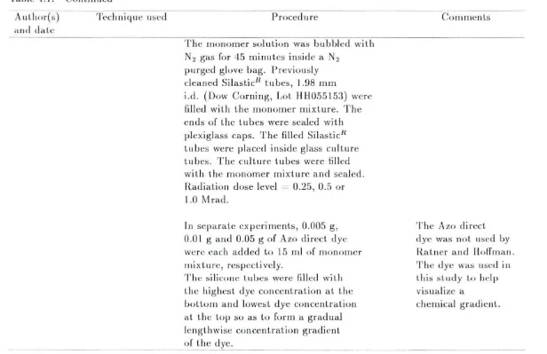
Table 4.1: Continued A11thor(s)
and da.te
'T'ech 11 i q ut~ 11 scd Procedure
The monomer solution was bubbled with N2 gas for 45 minutes inside a N2
purged glove bag. Previo usly cleaned Silas ticn tubes, 1.98 mm
i.d. (Dow Corning, Lot ll ll 055153) were fill ed with the monomer m ixture. The ends of the tubes were sealed with plexiglass caps. The fill ed Silastic11 tubes were placed inside glass culture tubes. The culture tubes were filled with the monomer mix ture a nd sealed. Radiatio n dose level - 0.25, 0.5 or
1.0 Mrad.
ln separate ex pe riments, 0.005 g ,
0.0 I g and 0.05 g o f Azo direct dye were each added to 15 ml of mo nomer mi xture, respectively.
The silicone tubes were filled with the hig hest d ye concentra tion at the bottom a nd lowest dye co11centratiu11 a t the top so as to form a gradual leng th wise concentration gradient of the dye. -
-Co111 rne11 ts
The Azo direct dye was not used by Ratne r and 11 off rna.n. T he dye was used in this st ud y l o help
vis ualize a
[image:38.787.84.700.92.491.2]33
4.2.2. Sample preparation
Silicone rubber (SR) tubing (Dow Corning, SilasticR ~Iedical Grade Tubing,
Lot HH 055153 , 1.98 mm inside diameter x 3.18 mm ou tside diameter) was boiled
in a
2%
aqueous sodium bicarbonate (Fisher Scientific, Lot 855518) solution for3 one-hour periods, using fresh solutions each time. This was followed by profuse
rinsing with distilled water and 3 washings in distilled \rnter for 30 minutes using
an ultrasonic cleaner. Finally, samples were dried at l00°C for 2~ hours.
4.2.3. Expe rime ntal set up a nd proce dure for irradiation
A special device was designed to hold the SilasticR samples in position during
irradiation (Figure 4.1).
The SilasticR sample (100 mm long) was fitted snugly inside a clean glass
support tube (3 mm inside diameter x 5 mm outside diameter). A plexiglass cap
was .inserted into the bottom of the sample tube to press the expandable SilasticR
firmly against the inside of the glass support tube . SilasticR Medical Adhesive
Silicone Type A (Dow Corning, Lot H 102560) was used to seal the bottom cap.
This was done 2-l hours prior to filling the lumen with monomer mixture to allow
the adhesive to polymerize and provide a good seal. A glass mandrel (capillary
tube of 1.39 mm inside diameter with both ends sealed with Hemato-Seal™ tube
sealing compound, Fisher Scientific) was placed coaxially into the sample tube and
was positioned by a slot drilled into the middle of the bottom plexiglass cap. This
3-!
1. Glass Mandrel
2. Monomer (with dye} 3. Silicone Rubber Tube 4. Glass Support Tube 5. Monomer (no dye} 6. Glass Culture Tube 7. Plexiglass Cap
[image:40.579.76.483.118.656.2]4. 5.
35
A total of 4 formulations were prepared for radiation grafting (in volume
% ) :
1. ,.\ 100 ml mixture containing 203 HE).IA , 13 EGDM, 39.53 methanol, and
39.53 distilled water. 0.01 g, 0.05 g and 0.1 g of Azo direct dye were each
added to 15 ml of monomer mixture, respectively.
2. A 100 ml mixt ure containing 203 HEMA , 23 EGD:vI, 393 methanol, 393 distilled water. 0.01 g, 0.05 g and 0.1 g of Azo direct dye were each added to
15 ml of monomer mixture.
3. ,.\ 100 ml mixture containing 203 HEMA , 23 EGDYI, 393 methanol, 393
distilled water. 0.005 g, 0.01 g and 0.05 g of Azo direct dye were each added to 15 ml of the mixture.
4. A 100 ml mixture containing 203 HEMA , 23 EGD:VI, 393 methanol and 393 distilled water. 0.1 g of Azo direct dye was added to 15 ml of the mixture.
Prior to irradiation, the space between the capillary tube and the inner walls
of the sample tube was filled with the mixtures with different dye concentrations.
Each of the three different dye solutions were loaded in 1 ml polyethylene syringes
fi tted wit h 23G hypo dermic needles. The sample t ube was flushed with a jet of N2
to rem ove any
0
2 present. The sample and support tube were held upright and 0.2ml of each mixture was carefully injected into the tube. Any gas bubbles formed were carefully removed. The mixture with highest dye in it was at the bottom of
the tu be, and the mixture with the lowest dye in it was at the top of the tube. The
top plexiglass cap was pressed onto the top of t he support tube, and the assembly
36
of Owens-Illinois). The culture tube was filled with the monomer mixture that did
not have any dye added to it and sealed. TeflonR Thread Seal Tape was placed on
the threads to make the cap airtight. The culture tube was placed horizontally in
a N2 filled desiccator and sealed. ~ovement of sample and handling was kept to
a minimum before irradiation to prevent intermixing of various dye solutions. A
series of radiation dose levels (0.25 Mrad, 0.5 ~Irad and 1.0 i'vlrad) were used for the different formulations. The length of irradiation was 54 minutes, 110 minutes
and 220 minutes for the three dose levels, respectively.
4.2.4. Characterization o f grafted silicone rubber tubes
Visual and op tical microscopic studies were done on all grafted samples. The
samples were studied within a few hours after grafting while t hey were still wet.
A section of each sample was also air dried for 24 hours and observations were
made after the samples were dry. 1 mm thick cross sections of the samples were
made using single edge industrial blades (Polysciences Inc., PA), and were viewed at lOx, lOOx and 400x using an optical microscope (Balplan Microscope, Bausch
and Lomb , Scientific Optical Products Division, Rochester, NY) . Cross sections of the radiation samples were also observed at 30x using a stereo microscope (NikonR
98660, Japan). Longitudinal sections were also made using single edge blades, and
samples were studied for d ye distribution. The sections were mounted by laying the
samples straight on a flat glass plate and taping the ends to the glass plate. ·weight measurements were made for the samples grafted by the IPN and
37
Princeton, NJ) . The initial weight of cleaned, dry samples and the final weight
of dry grafted samples were obtained and the
3
weight change was calculated as follows :38
5. RES ULTS AND DISCUSSION
5.1. R esults
5.1.1. R esults fro m the diffe r e nt techniques used in g rafting HEMA
The various methods which were tried in grafting HE ~IA onto silicone rubber
tubes and the procedures followed are described in detail in Table 4.1. The results
obtained are listed in Table 5.1.
5.1.2. R adiation init iated poly m e rization
Ratner and Hoffman (1974, 1975) and Knoll (19 0) have reported the degree
of graft and water imbibing properties of various radiation grafted bydrogel
for-mulations on silicone rubber (nonporous) and polyethylene terephthalate (porous
fabric), respectively.
By
comparison. this work reports that the same hydrogelfor-mulation with Yarying amounts of Azo direct dye can be grafted on silicone rubber
simultaneously using the radiation initiated polymerization method. Table 5.2 lists
fabrication and graft data for a number of hydrogel formulat ions. The
39
Table 5.1: Results obtained from the different methods used in grafting HE~IA onto silicone rubber
Technique used
Free radical initiated polymerization reaction Interpenet rating Polymer t\etworks (IPN)
Dip-coat method
Dip-coat method followed by the free radical initiated technique to give the second HEMA coat
The IPN method followed by the free radical initiated poly-merization method
6°Co irradiation
Radiation grafting with the various hyd -rogel-dye solutions. Formulation details are given in Table 5.2
Results
Even though Pinchuk et al. report that the reaction time was 15 minutes, in the current study the reaction time was seen to be longer (100-120 minutes) for polymerization. Complete polymerization could not be obtained using this method.
Significant grafting of the monomer onto the inner wall of t he silicone rubber could not be achieved by the IPN method. Weight gain percentages were
<
13.
Significant weight gains for silicone rubber t ubes were not obtained for samples which received 6 coatings of the solubilized polymer.
Could not obtain significant grafting of HE~L\. onto t he si licone rubber substrate.
No significant grafting was achieved . T he adhesion of HEl\IA onto the silicone rubber substrate was poor.
Visual and microscopic observations in dicated significant grafting of the HEYIA. A layer 0.13 mm t hick built upon the inner wall of the tu be, and material penetrated 67 µm into the wall of the tube.
[image:45.580.75.510.82.713.2]40
Table 5.2: Fabrication data for radiation initiated polymerization of hydrogel on SilasticR tubes
Composition (% by volume)
Solvent Azo0 Dose
HE:VIA EGDM :Vl ethanol/ H20 Direct Dye Level 0 bservations (1003 ) (in grams) (:\Irad)
20 1.0 39.5/ 39.5 0.01 0.25
20 1.0 39.5/ 39.5 0.05 0.25 )I' o visible 20 1.0 39.5/ 39.5 0.1 0.25 reaction
20 2.0 39.0/ 39.0 0.01 0.25
20 2.0 39.0/ 39.0 0.05 0.25 )I' o visible 20 2.0 39.0/ 39.0 0.1 0.25 reaction
20 2.0 39.0/ 39.0 0.25 )I' o visible reaction
20 2.0 39.0/ 39.0 0.1 0.25 )I' o visible reaction
20 2.0 39.0/ 39.0 0.005 0.5 Firm gel stained 20 2.0 39.0/ 39.0 0.01
0.5
yellow· the dye 20 2.0 39.0/ 39.0 0.05 0.5 penetrated 5 µminto the wall of the tube.
20 2.0 39.0/ 39.0 0.005 0.25 Flaky loose 20 2.0 39.0/ 39.0 0.01 0.25 gel stained 20 2.0 39.0/ 39.0 0.05 0.25 yellow
20 2.0 39.0/ 39.0 0.005 1.0 Firm gel stained 20 2.0 39.0/ 39.0 0.01 1.0 yellow; a layer 20 2.0 39.0/ 39.0 0.05 1.0 0. 13 mm thick built
up on the inner wall of the tube, and material pene-trated 67 µm into the wall of the tube.
0
[image:46.580.69.499.136.649.2]"11
5 . 1.3. Opt ical microscopic r es ults
Studies using compound and dissection microscopes were done on cross sections and longitudinal sections of the grafted samples as soon as possible after irradiation.
Although the N-vinyl-2-pyrrolidone (NVP ) graft penetrates the silicone rubber
ma-trix, the HEl'vIA graft forms a layer on the surface of the sili cone rubber matrix
(Horbett and Hoffman. 1975; Ratner and Hoffman, 1975; Ratner et al. , 1975).
Op-tical microscopic studies (at lOx) of the 20
%
HE1IA. 2% EGD.\I , 393 .\IeO H and393 H2
0
composition at 0.5 and 1.0 .\Irad dose levels clearly showed t he existenceof a yellowish layer of HE.\1A on the inner walls of the tubes. The layers were
approximately 50 µm thick. These layers were present even after extraction with a
503 et hanol and 503 H2
0
mixture for 2 hours.Longitudinal sections of a SilasticR sample tube grafted with 3 different
hydrogel-dye compositions are shown in Figure 5.1. T he formulation chosen for this sample
contained 203 HEl'vIA , 23 EGD :VI, 393 MeOH and 393 distilled H2
0.
5.2. Discussio n
The free radical initiated polymerization , the IP~ , and the dip-coating
meth-ods of grafting HEMA onto sili cone rubber tubes of 1.98 mm i.d . were not very
successful. Most of the problems encountered with these methods were poor
adhe-sion of the HEMA onto t he silicone rubber, poor graft percentages a nd also very
little control of the dye distribution in the HE.\IA matrix. Because of the sequential
steps that have to be followed in applying these methods, more control over the dye
-12
-l3
The radiation initiated polymerization method worked very well for graft ing
the various HE [A-dye formulations onto silicone rubber. By using di fferent dye
amounts in the same hydrogel composition and by filling the lumen of t he SilasticR
tu bing with these different solutions, a concentration gradient of the dye was
estab-lished along the axis of t he tube. Diffusion of dye to areas of lower concentration
is not a severe problem if the irradiation is done immediately after tubes are filled
and if movement of samples is kept to a minimum. Diffusion can be kept to a
minimum by filling the lower parts of the SilasticR t ube with t he relati vely high
dye concentrations and the upper parts with relatively low dye concent rations. To
reduce diffusion. it is also useful to lay t he Silastic tubes horizontally after filling
and maintain this position until irradiation begins. A little diffusion between the
different liquid interfaces is advantageous because this will allow gradual changes of
dye concentration rather than abrupt changes in concentration at the interfaces.
·By varying the amount of HEl\IA-dye monomer mixture added to t he interior
of the SilasticR t ube, the distance OYer which the concentration gradient changes
can be altered. By using different sized glass mandrels, the thickness of HEMA on
the inner wall of a silicone rubber tube can be changed. Thus, different sizes of
l l
6. CONCLU SION
This study represents the initial steps of an attempt to utilize hydrogel
formu-lation on a tubular substrate to produce a nerve cuff. Since nene fibers follow a concentration gradient of the nerve growth timulanl. it is important to develop a
method by which a chemical gradient can be established along the tubular substrate.
T he current work is successful in developing a technique to lay down a
concentra-tion gradient of a dye in the grafted hydrogel matrix along the axis of a silicone rubber tube. By replacing the dye with nerve growth stimulants, it is anticipated
t hat hydrogel grafted silicone rubber tubes can be used as nerve cuffs. The 6°Co
irradiation grafting method is satisfactory fo r fabricating hydrogel grafted tubes
of varying lengths and diameters in which a dye is incorporated into the hydrogel
matrix in increasing concentrations from one end of the tube to the other.
The chemotactic effect of :"J"G F and other neuropeptides on nerve fiber
regen-eration has been emphasized by Charlwood et al. (1972) and Letourneau (197 ).
Based on these facts , emphasis was laid on the fu ture development of a nerve cuff
which will have biologically active molecules distributed along a lengthwise
concen-tration gradient. This study shows t hat a substance (Azo direct dye in this case)
can be distributed to form a concentration gradient in a HE).IA matrix. This is
[n these initial experiments . .-\zo direct dye was used instead of a chemotactic agent
because it is easy to detect, procedures for use with hydrogels are known and it is less costly. The formulation containing 203 HEM.-\, 23 EGDM, 39% methanol and
39% H20 (irradiation dose of 0.5 Mrad ) was chosen based on 'pore' size req ui
re-ments. The dye solutions containing 0.005 g, 0.01 g and 0.05 g of A.zo dye each in
15 ml of the monomer mixtures worked best in visualizing the dye con centration
gradient easily. The formulati on chosen had a micro\•oid size of
<
lµm, which wasable to entrap the dye molecules (:\1.W 624.56). Since the nen·e growth factor
molecules are larger (:\I.v\' = 13.250), this pore size should be able to also entrap
the biologically acti ve molecules. :-\!so diffusion rates should be lower for the nerve
growth factor molecules in t he hydrogel matrix sin ce they are larger. Hence, in
future exp eriments with the growth factor, diffu sion down concentration gradients
should no t be a critical factor.
Future research on this project might include substituting commercially
avail-able :\GF in place of the dye, tudyi ng the effects of 6°Co radiation on the . CF
(i.e., will radiation denature the protein), tudying the interaction between growing
neurons and the proteins t rapped in t he hydrogel matrix, and determining the
ad-hesive requirements for attachment of neurons to the hydrogel substrate. Because
of elevated temperatures reached during irradiation, the effects of increased
tem-perature on the growth stimulants should be studied. Additional investigations of
hydrogel formulations producing other characteristics (i .e., microporosity, chemical,
mechanical strength) should be performed and results should be catalogued. T hese
46
the controlling factor(s) for nerve adhesion. fiber growth and direction of growth.
All these factors have to be taken into considerat ion and all problems have to be overcome before a suitable off-the-shel f nerve cuff can be fully deYeloped fo r in vivo
47
7 . BIBLIOGRAPHY
Andrade, J. D. 1973. Interfacial phenomena and biomaterials. Jl ed. Instrum. 7:110- 120.
Barbin, G., :\I. Manthorpe, and S.Varon. 1984. Purification of the chick eye ciliary neuronotropruc factor. Journal of N eurochemistry 43:1468- 1478.
Barde, Y.A., D. Edgar , and H . Thoenen. 1982. Purification of a new neurotrophic factor from mammalian brain. Th e EMBO Journal 1:549- 553.
Benowitz, L.
I.,
and L. A. Greene. 1979. Nerve growth factor in the goldfish brain: biological assay studies using pheochromocytoma cells. Brain R es. 162:164-168.Boyd, L. F .,
R.
A. Bradshaw, W . A. Frazier,R.
A. Hogue-Angeletti . I. Jeng, M . \V. Pulliam, and A. Szutowicz. 197.J. 1Iinireview : _ erve growth factor. Life Sciences 15:1381- 1391.Braley, S. 1970. The chemistry and properties of the medical-grade silicones. J . . Ma cromol. Sci. Chem. A.4:529- 544.
Bruck, S. D. 1972. Biomaterials in medical devices. Trans. Am. Soc. Artificial Internal Organs 18:1- 9.
Bruck, S. 0. 1973. Polymeric materials: Current status of biocompatibili ty. Bio-mater. !vi ed. Devices :!rtif. Organs 1:79- 9 .