Abstract: Most inspection companies or any companies that involve in doing this inspection were usually do not have a clear view of which method was best to use in MPI. It is sometimes unclear whether the magnetic field was sufficiently strong to give good indications. So theoretically, both can be used as an inspec-tion tool and company will choose the best method and resolving the inspection. Dry particle inspection was best used when look-ing for shallow cracks near rough surface. Components with paint or rust on them can reduce the sensitivity of the test yet still allow for the desired result. Wet suspension Particles are when particles are applied while they are held within a liquid carrier, allowing for even coverage, and to highlight leakage. It provides optimum contrast with the tested surface, allowing for greater detail than dry particles. They are particularly useful for smooth surfaces as these particles will settle in rough surfaces. The ob-jective was to perform Magnetic testing analysis on selected bolt using dry method. To perform magnetic testing analysis on se-lected bolt using wet method. To determine the sensitivity com-parison between wet and dry method on selected bolts. To con-clude wet method magnetic testing has been proven to be more sensitive to defect compare to dry method magnetic testing as evidence by Table 3 at 70% and 50% respectively.
Keywords: Magnetic Particle Inspection (MPI), Dry Method, Wet Method
I. INTRODUCTION
General Introduction
One of the utmost important aspect in aviation industry is inspection, which may be conducted in many forms and methods. Through inspections have duly proven that they not only promote continuous development in many aspects such as maintaining live aircrafts’ parts [1-3], discovering new measurements and updates of the current equipment [4-8] and materials [9-10] used in the aviation industry, pro-moting educational research at higher learning educations [11], and generating profits for different stakeholders at many levels [12-14]; but also prevent from the losses of human lives [15-19]. One of those inspections involve mag-netic testing.
Magnetic Testing uses one or more magnetic fields to lo-cate surface and near-surface discontinuities in ferromagnet-ic materials.
Revised Manuscript Received on May 05, 2019.
Mohammad Iqmal Mohd Ali, Universiti Kuala Lumpur, Malaysian In-stitute of Aviation Technology, Dengkil, Selangor, Malaysia
Muhammad Zarief Daniel Besri, Universiti Kuala Lumpur, Malaysian Institute of Aviation Technology, Dengkil, Selangor, Malaysia
Md Khairul Amiza Md Hairudin, Universiti Kuala Lumpur, Malaysi-an Institute of Aviation Technology, Dengkil, SelMalaysi-angor, Malaysia
Magnetic testing can be conducted by using two methods which is the dry and wet method [20]. The wet method is commonly known as the Fluorescent Magnetic Particle In-spection (FMPI). On the other hand, the dry methods are dusted onto the surface of the test object as the item is mag-netized. Dry particle inspection is well suited for the inspec-tions conducted on rough surfaces [21].
Problem Statement
Most inspection companies or any companies that involve in doing this inspection are usually does not have a clear view of which method is best to use in MPI. It is sometimes unclear whether the magnetic field is sufficiently strong to give good indications. So theoretically, both can be used as an inspection tool and company will choose the best method and resolving the inspection. Dry particle inspection is best used when looking for shallow cracks near rough surface. Components with paint or rust on them can reduce the sensi-tivity of the test yet still allow for the desired result [22]. Wet suspension Particles are when particles are applied while they are held within a liquid carrier, allowing for even coverage, and to highlight leakage. It provides optimum contrast with the testing surface, allowing for greater detail than dry particles. They are particularly useful for smooth surfaces as these particles will settle in rough surfaces.
Research Objective
To perform Magnetic testing analysis on selected bolt using dry method
To perform magnetic testing analysis on selected bolt using wet method
To determine the sensitivity comparison between wet and dry method on selected boltsResearch Goals
Main goal for intended final year project is to determine the efficiency of the wet method compare to dry method regarding flaw detection and the subsequent time consume and cost.
Scope and Limitation
The final year project scope only limited to selected air-craft standard steel bolt using Bouw and Widen equipment. Other application on other bolt might not yield the result intended.
Comparison of Magnetic Particle Inspection of
Dry and Wet Method to the Inspection on
Aircraft Bolts
Summary
Magnetic Particle Inspection are usually to evaluate fer-rous metal on modern or current aircraft but for this research is focusing more on age aircraft. This is by inspecting air-craft bolts for any defect. The inspection using Magnetic Particle Inspection use two methods which is the Dry Meth-od and Wet MethMeth-od.
II. LITERATURE REVIEW
Non-Destructive Technique
Dwivedi et. al. (2018) described nondestructive testing are methods to evaluate material integrity for surface or internal flaws or metallurgical condition without interfering in any way with the destruction of the material or its suitability for service [23].
Magnetic Particle Inspection
Singh & Singh (2016) described that Magnetic Particle in-spection is a nondestructive method that detects discontinui-ties that are either buried slightly below or open to the mate-rial or weld surface. Its advantage over visual inspection is that it can detect defects that are buried below the surface as well as surface opening defects that are too small to be visi-ble by the naked eye [24].
Summary
Magnetic particle inspection is still on the efficient meth-od that is being use in the NDT industry as it gives a gometh-od result and precise result. This must be practice in any other industry because it could save life and might be cost. Cata-strophic event could be prevented if conducting Magnetic Particle Inspection on components that are ferrous. MPI can enhance and control the manufacturing processes and sup-port in product development of material. Hence, researchers utilized all the necessary equipment and documentations that are readily available for training purposes at UniKL MIAT to conduct the experiments [25].
III. METHODOLOGY
Lighting
The magnetic particle inspection can be performed uti-lizing particles that are profoundly noticeable under white lighting conditions or particles that are exceptionally un-mistakable ultraviolet conditions.
Visible light
[image:2.595.306.545.76.267.2]According to the Standard Practice for Magnetic Particle Inspection (ASTM), visible light intensity measurement needs to be conducted upon initial light installation or when changes occur that cause the light intensity to change and at the intervals specified in Table 1 (Figure 1). Visible light shall be used when examining with non-fluorescent magnetic particles.
Table. 1 Table Required of Verification Intervals on Lighting (ASTM Table)
Black Lights
[image:2.595.338.517.359.485.2]Inspection black lights might meet the necessities. The base satisfactory force is 1000µW/cmˆ2 (10W/m^2) at the surface being inspected. Black lights shall be checked peri-odically for cleanliness and integrity and shall be cleaned, repaired or replaced as appropriate.
Fig. 1 Black Lights Restricted Area Examination
Where lamps are physically too large to directly illumi-nate the examination surface, special lighting, such as UV pencil lights or UV light guides or borescopes shall be used. The picture saw must have adequate determination to suc-cessfully inspect the required discontinuities.
[image:2.595.334.545.574.826.2]IV. ANALYSIS Introduction
Research and series of experimental has been conducted to determine the sensitivity of the magnetic testing wet method and dry method. Result were compared to determine the sensitivity yield by both method and to determine the best method respectively.
The objective of the research was to perform Magnetic testing analysis on selected bolt using dry method to per-form magnetic testing analysis on selected bolt using wet method and to determine the efficiency comparison between wet and dry method on selected bolts
Bolt Sampling
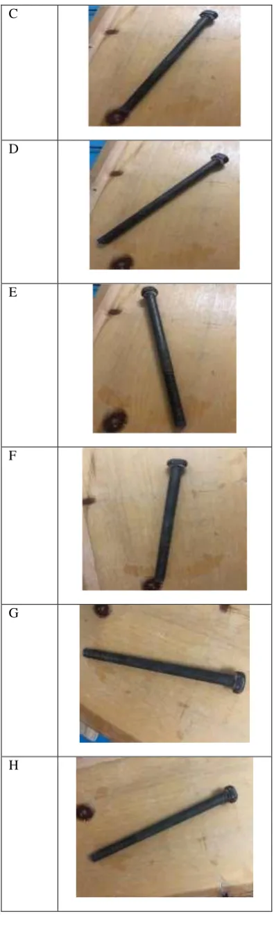
Ten AN4-6 3/8-24 TPI aircraft standard bolt were selected for the wet method and dry method sensitivity comparison. The bolts selected share the same dimension for the purpose of controlling the accuracy of the research as showed by Figure 3. The bolt with a crack or corrosion in the shank, radius or thread is rejected. Table 2 shows 10 identical bolts. The crack that has been found was 3 inches below the bolt head
[image:3.595.328.526.47.732.2][image:3.595.81.265.341.487.2]
Fig. 3 AN4-6 3/8-24 TPI Table. 2 Ten Identical Bolts Sample
Bolt
Ten Identical AN4-6 3/8-24 TPI Bolt
A
B
C
D
E
F
G
[image:3.595.71.268.502.742.2]I
J
Wet Method
[image:4.595.308.547.39.645.2]Wet method magnetizing has been conducted on series of 10 AN4-6 3/8-24 TPI. The test was conducted in a control environment. The result was tabulated as evidence by Table 3. The results that showed below was between the compari-son of wet method and dry method in term of which method has a more sensitivity. This method has been conducted as per ASTM E1444. Table 3 showed a tremendous result on wet method in terms of sensitivity.
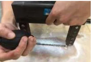
Fig. 4 Bolt Using Wet Method Dry Method
[image:4.595.55.268.46.273.2]Ten identical AN4-6 3/8-24 TPI bolt was tested using the dry method. Most crack on the bolt cannot be identified visually by using the dry method. The result is shown in Table 3. From the table, dry method showed just a few signs of crack detection on some of the bolts. This method has been conducted as per ASTM E1444. Table 3 showed that the dry method is less sensitive than wet method although dry method has a portability advantage.
Fig. 5 Bolt Using Dry Method
[image:4.595.67.269.380.528.2]Results of Wet and Dry Method
Table. 3 The comparison of sensitivity of dry and wet method
# Sample Bolt
Wet Method
Dry Method
Remarks
1 A 1 1 Crack was found
on the bolt thread. Bolt must be dis-carded
2 B 1 0 Hair line crack
was found on bolt shank.
Bolt is still usable
3 C 1 1 Fatigue crack was
found below the bolt head. Bolt must be discarded
4 D 1 1 Fatigue crack
found below the bolt head. Bolt must be dis-carded
5 E 1 0 Hair line crack
was found on bolt shank.
Bolt is still usable
6 F 0 0 No crack found
7 G 1 1 Hair line crack
was found on bolt shank.
Bolt is still usable
8 H 0 0 No crack found
9 I 1 1 Fatigue crack was
found below the bolt head. Bolt must be discarded
10 J 0 0 No crack found
Analysis based on charts
[image:4.595.94.245.662.765.2]The 80% and above was the amount of sensitiveness that detected the fatigue crack, crack and hair line crack on 3 different locations which is on the shank, below the bolt head and the bolt thread.
Fig. 6 Wet Method Chart
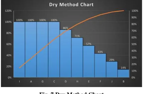
From the chart below, 5 sample bolts of AN4-6 3/8-24 TPI has literally showed a lower percentage of sensitivity for detection of cracks compared to the previous chart. The 80% and above of sensitiveness detected the cracks. A small amount of percentage was showed in Figure 7 below compared to wet method. The dry method can be considered a less preferable method to be use as the sensitivity to detect cracks are lower than wet method, as most of the bolt has small cracks and can mostly detected by wet method. As evidence by Table 4 and further visualize by Figure 7. The 80% and above was the amount of sensitiveness that detect-ed the fatigue crack, crack and hair line crack on 3 different location which is on the shank, below the bolt head and the bolt thread.
Fig. 7 Dry Method Chart
V. CONCLUSION
From the evaluation that has been taken, the best method should be used is the wet method as it could give a better sensitivity rather than the wet method as evidence by Table 3.
The objective was to perform Magnetic testing analysis on selected bolt using dry method. To perform magnetic testing analysis on selected bolt using wet method. To determine the sensitivity comparison between wet and dry method on selected bolts.
The investigation of magnetic testing via dry method on selected bolt has been completed as evidence by database on Table 4. The investigation of magnetic testing via wet
meth-od on selected bolt has been completed as evidence by data-base on Table 4.
To conclude wet method magnetic testing has been prov-ing to be more sensitive to defect compare to dry method magnetic testing as evidence by Table 3 at 70% and 50% respectively.
Recommendation
A good recommendation to the company that use Magnet-ic Testing as a part of their inspection techniques, wet meth-od will most preferable to use as it gives the best detection rather than the dry method. Besides that, to keep our envi-ronment from being harm by any harmful and hazardous material the wet method fluid must be in a form of a water base rather than a petroleum base. This is because the petro-leum base could emit harmful gaseous that are dangerous to the environment. Furthermore, water base has a short prepa-ration time rather than the petroleum base because water base only needs a half hour while the petroleum base needs an hour.
Future work
For a better progress in the future in conducting an inspec-tion on aircraft bolts it is recommended if you would use other types of Non-Destructive Testing method which are more advance and more accurate in term of sensitivity such as radiography, eddy current and ultrasonic.
REFERENCES
1. Zainal Ariffin, M., Johari, M., & Ibrahim, H. (2018). The needs of aircraft avionics' radio line replaceable unit repair center at UniKL MIAT. International Journal of Engineering and Technology, 86-88. 2. Johari, M., Jalil, M., & Mohd Shariff, M. (2018). Comparison of
horizontal axis wind turbine (HAWT) and vertical axis wind turbine (VAWT). International Journal of Engineering and Technology, 74-80. 3. Omar, S., Johari, M., & Abdul Samad, A. (2018). Assessment on risk
management of helicopter services for offshore installations.
International Journal of Engineering & Technology, 229-231. 4. Muhd Zaimi, M., Rosdi, I., & Dahdi, Y. (2019). Tensile Test on
Sisal/Fibre Glass Reinforced Epoxy-based Hybrid Composites. International Journal of Innovative Technology and Exploring Engineering, 604-607.
5. Muhd Zaimi, M., Nazran, M., & Basit, R. (2019). Design and Testing UniKL MIAT CF 700 AFT Fan Turbofan Fuel Tank with Indicator. International Journal of Innovative Technology and Exploring Engineering, 590-595.
6. Azman, A., & Abdul Rahman, A. (2019). Potential and challenges of drop-in biojet fuel in Malaysia. International Journal of Innovative Technology and Exploring Engineering, 556-563.
7. Mohd Ali, M., & Ahmad Khairul Azman, N. (2019). Automated Deployable Protection Unit for Drones. International Journal of Innovative Technology and Exploring Engineering, 564-574.
8. Mohd Ali, M., & Husni, M. (2019). Efficiency of Solar Cells for UAV. International Journal of Innovative Technology and Exploring Engineering, 575-577.
9. Ya'acob, A., Razali, D., Anwar, U., Radhi, A., Ishak, A., Minhat, M., . . . Teh, C. (2017). Preliminary Study on GF/Carbon/Epoxy Composite Permeability in Designing Close Compartment Processing.
AeroMech17 (pp. 1-9). Pulau Pinang: IOP Publishing Ltd.
[image:5.595.50.287.452.608.2]11. Johari, M. K., & Jamil, N. Z. (2014). Personal problems and english teachers: Are they always bad? . International Journal of Applied Linguistics and English Literature, 163-169.
12. Khairuddin, M., Yahya, M., & Johari, M. (2017). Critical needs for piston engine overhaul centre in Malaysia. IOP Conference Series: Materials Science and Engineering (pp. 012013 (1-5)). Bristol: IOP Publishing Ltd.
13. Bardai, A., Er, A., Johari, M., & Mohd Noor, A. (2017). A review of Kuala Lumpur International Airport (KLIA) as a competitive South-East Asia hub. IOP Conference Series: Materials Science and Engineering (pp. 012039 (1-10)). Bristol: IOP Publishing Ltd. 14. Ishak, F., Johari, M., & Dolah, R. (2018). A case study of LEAN
application for shortest lead time in composite repair shop.
International Journal of Engineering and Technology, 112-119. 15. Azizan, M., Fard, M., & Azari, M. (2014). Characterization of the
effects of vibration on seated driver alertness. Non-linear Engineering-Modelling and Application Journal, 163-168.
16. Amzar, M., Fard, M., Azari, M., Jazar, R., & Maeda, S. (2017). Influence of vibration on seated occupant drowsiness measured in simulated driving. Applied Ergonomics Journal, 348-355.
17. Abdul Samad, A., Johari, M., & Omar, S. (2018). Preventing human error at an approved training organization using Dirty Dozen.
International Journal of Engineering and Technology, 71-73. 18. Muhd Zaimi, M., & Zulkifli, M. (2019). Analysis on the Aerodynamic
Efficiency of Modified Blended Wingtip. International Journal of Innovative Technology and Exploring Engineering, 600-603.
19. Amzar, M., Fard, M., Azari, M., Benediktsdttir, B., Arnardttir, E., Jazar, R., & Maeda, S. (2016). Influence of vibration on seated occupant drowsiness. Industrial Health Journal, 1-12.
20. Raj Kumar, R., Subashini, K., Ragulkumar, J., & Sathish, E. (2017). Design and Development of SCR Firing Circuit for MPI Current Source. International Journal of Advanced Research in Electrical, Electronics and Instrumentation Engineering, 1547-1559.
21. NDT Resource Center. (2009). Retrieved from Dry Particle Inspection:
https://www.nde-ed.org/EducationResources/CommunityCollege/MagParticle/TestingPr actices/Dry%20Particle.htm
22. DNV.GL. (2017, May). Retrieved from
https://rules.dnvgl.com/docs/pdf/DNVGL/RP/2017-05/DNVGL-RP-G103.pdf
23. Dwivedi, S., Vishwakarma, M., & Soni, P. (2018). Advances and Researches on Non Destructive Testing: A Review. Materials Today:Proceedings, 3690–3698.
24. Singh, R. (2015). Magnetic Particle Testing. In Applied Welding Engineering (pp. 327–334). Amsterdam: Elsevier.
![Does wave function (ψ) get real in quantum experiment? [3] answer is – no, it is only a mathematical tool mind incorporation in physics](data:image/gif;base64,R0lGODlhAQABAIAAAP///wAAACH5BAEAAAAALAAAAAABAAEAAAICRAEAOw==)