International Journal of Innovative Technology and Exploring Engineering (IJITEE) ISSN: 2278-3075, Volume-8, Issue-11S, September 2019
Abstract— Technology has grown vastly in all directions of the world. The influence it has had on the world over the past 50 years has been exponential and the need for further growth is demanding. Human Computer interaction these days exists in various forms. Ever since the computer has dominated the business age, there have been huge leaps in progress towards science. These days a person need to use a series of multiple peripheral devices to simply send data from one system to another. However the existing devices used for Human computer interactions are limited in their potential and capabilities. More devices would thus require a more sophisticated touchless control system. This system however has been deemed to be too expensive and furthermore it requires a lot of skill to control and maintain. Thus the proposed system would need to be fairly cheap to produce and simple enough that the users will not be intimidated by its complexity and design.
Keywords: system, Arduino, sensor, capacitor, motion, tracking, controller, operation, projection, simulation, conductor, interface,
I. INTRODUCTION
The main principle of the project is to use a micro controller to measure the change in the capacitance effect between two metal plates when the dielectric changes. The system described uses this to measure the changes across a rectangular coordinate system as well as a polar coordinate system. Thus the system can be used to track movement to a degree or scan surfaces at a 3D scale in order to find differences/ cracks etc. The capacitor is a component which has the ability or “capacity” to store energy in the form of an electrical charge producing a potential difference across its plates, much like a small rechargeable battery. There are many different kinds of capacitors available from very small capacitor beads used in resonance circuits to large power factor correction capacitors, but they all do the same thing, they store charge.In its basic form, a capacitor consists of two or more parallel conductive (metal) plates which are not connected or touching each other, but are electrically separated either by air or by some form of a good insulating material such as waxed paper, mica, ceramic, plastic or some form of a liquid gel as used in electrolytic capacitors. The insulating layer between a capacitors plates is commonly called the Dielectric.Due to this insulating layer, DC current cannot flow through the capacitor as it blocks it
Revised Manuscript Received on September 10, 2019.
Nishant Mathew Surathu, Department of Electronics and Communications engineering, Saveetha School of Engineering, Chennai, Tamilnadu, India
(email: [email protected])
Mrs. T.J.Nagalaksmi, Asst. professor, BE (ECE), ME (applied electronics) (PhD), Department of Electronics and Communications engineering, Saveetha School of Engineering, Chennai, Tamilnadu, India.
(email: [email protected])
allowing instead a voltage to be present across the plates in the form of an electrical charge.
II. LITERATURE SURVEY
The world today as we know it is a growing technological hub and thus the need for new HCI system is constantly growing. This field of research has sprouted a lot of interest over the past several years and is still growing. The result of which gives rise to the Microsoft Kinect controller, The Leap motion controller and the arm band controllers. Such controllers are however very limited in their potential and can be very complicated to use unless the user has undergone some extent of professional training. In this section I shall discuss the other touchless HCI systems in existence and compare them with one another for a better and broader point of perspective.
A. Microsoft Kinect controller
The Microsoft Kinect was a controller that was designed mainly as a gaming platform to recognise motion. It was designed as a hands free competitor to the Nintendo Wii. The controller works such that it projects infrared lines so as to chart the basic structure of the user present in front of it and also uses a high resolution camera that uses image processing software to track the movement of the user in real time. The controller is very effective and quite simple to use when the platform is provided however it tends to be quite complex and difficult to operate manually as a control system. More over the controller is not set for outside environments and requires a great deal to set up a working platform for it. Furthermore the camera and IR sensors present on the Kinect controller has proven to be very expensive.
B. Leap Motion controller
The leap motion controller was a sophisticated HCI system that was designed with a wide range of capabilities. The system uses technology that is very similar to that of the Microsoft Kinect Controller. The system was designed with an open source platform that enables the user to use is in any field conditions and given its size makes it very portable. The controller’s company platform is also very simple and easy to use and is used for various fields. Although it is very comparable to the Microsoft Kinect, its small size and capabilities show that it can be interfaced onto a much larger network of leap motion controllers for more data input. The system however is very limited as it has a short range of detection and isn’t very powerful.
Three Dimensional Capacitive Control System
using Arduino Uno
Figure 2: leap motion controller[3]
C. Ultrasonic sensor
The ultrasonic sensor is a device that is used generally for the distance calculations. It consists of an emitter and receiver sub system which work together to determine an objects distance. The emitter is used to transmit ultrasonic waves into the free space and the receiver picks up on the reflection of the ultrasonic waves. Based on the time it took to return and the power of the receiver’s input waves, The object’s distance and size can be fairly easily determined. This sort of sensor is usually placed on an arm band and the user can be placed inside a sealed and closed environment like a box. Based on the user’s distance from the walls the multiple ultrasonic sensors from the various bands can be used to track movement within the closed environment. However such a system is not very effective and highly inaccurate due to the amount of data input into the system at the same time and the receiver could pick up on the reflections of other ultrasonic waves as well.
D. Accelerometer
The accelerometer is a sensor that can be used to measure acceleration based on the 3D axis including gravity. They are electromechanical sensors that are commonly quite cheap and easy to use. The accelerometer can be used to track different movement provided the sensor is placed on the specific points. Its uses best are best shown in the case of Virtual Reality (VR) technology. The goggles used contain main different accelerometers that are strategically placed at different points so as to track movement of the head and replay it to the screen thus enabling the virtual reality experience.
E. 3D capacitive control system
The above subdivisions clearly define the existing touchless HCI systems that are active in the world and their disadvantages against each other. The proposed system has thus been designed to not only consider the advantages of these systems but to also overcome their disadvantages. The systems materials can be cheaply manufactured and a micro controller board for its specific use could be easily designed and cheaply manufactured in bulk amounts. The system simply uses the piezo electric effect that is generated when charges are stored in an electric field. The capacitance can be easily varied based on the changes in the dielectric present in the centre of the field. The concept of the proposed system is that it is used under 3 dimensional conditions to generate a larger capacitive field of charge.
three metallic plates. By doing so, Different controls can be programmed for different parts of the cube to have different functions.
III. METHODOLOGY
A. Arduino Uno
Arduino is an open source computer hardware and software company that designs and manufactures single board micro controllers. The Arduino uno is a medium sized micro controller that is fairly reasonably priced and can be used with sensors and other peripherals to design various projects. The Arduino is able to receive and transmit data and also capable of processing it as per the user’s desire. The single board micro controller depends on an ATMEGA328P chip. The Arduino is very sophisticated in design and is capable of a lot given the right conditions. Being open source there are various different versions of the Arduino board and various shields that can be used with it for networking and communication etc.
Figure 3: Arduino Uno microcontroller board [7]
B. MATLAB
MATLAB is a computer simulated environment that can perform mathematical calculations and run graphing algorithms to simulate various electronic device readings and outputs. MATLAB is also very easy to interface with other programming languages like C, C++, python, java and including hardware like the Arduino board and Raspberry Pi. MATLAB allows matrix manipulations, plotting of functions and data, implementation of algorithms, creation of user interfaces and calculation of signal processing.
C. FRITZING
Fritzing is also a simulator with is used for the design of circuits. It contains a vast library of components and circuits including micro controllers ranging from 8051 to the Arduino Mega. Fritzing keeps as updated library of current components and circuit design trends and enables us to design any circuit imaginable in a very sophisticated manner.
D. Design
International Journal of Innovative Technology and Exploring Engineering (IJITEE) ISSN: 2278-3075, Volume-8, Issue-11S, September 2019
[image:3.595.59.293.154.322.2]planes need to be made using a conductive surface so that it can generate a capacitance effect among the three planes as shown in the figure 4. The above figure shows the system designed using tin foil and the conductive element for the planes. A plastic box is used to support the tin foil for the system. The three individual planes of the system are then connected to the different voltage output point of the Arduino Uno
Figure 4: Circuit diagram of the proposed system using Fritzing
board in parallel through a series connection of resistors for each plate as shown through figure 5.
Upon turning on the system, the capacitance is kept at an initial constant level using the air as the dielectric. However when the hand is placed inside the cube, the dielectric changes and thus the capacitance within the cube changes in a particular direction. This is noted by the Arduino Uno and is shown through the interface as the output. MATLAB is also used in order to graph the
change in capacitance through the 3 different plates to show which of them are active.
Figure 5: design of the proposed system
IV. RESULTS
The interface for the system was designed using the Arduino software to track the movement within the cube and the MATLAB software to track the activity of the different planes in the cube.
A. Arduino interface
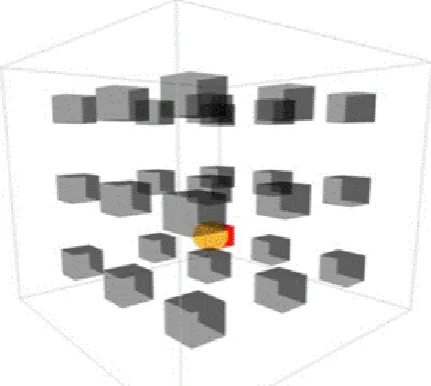
[image:3.595.324.540.208.401.2]The above figures show the different outputs received from the Arduino software. Figure 6 shows how the tracking of the hand is done due to the various changes in capacitance in the different fields. The yellow ball shows the placement of the hand. Figure 7 shows the different planes of the system’s interactions. The first column represents the X plane, the middle column represents the Y plane and the right column represents the Z plane. The numbers show the change in voltage due to the change in the capacitance through done through the hand changing the dielectric within the cube.
[image:3.595.70.293.420.607.2]Figure 6: Interface of the Arduino software
Table 1: Arduino sketch for set-up #define resolution 8
#define mains 50
#define refresh 2 * 1000000 / mains void setup() {
Serial.begin(115200); for(inti = 2; i< 14; i++) { pinMode(i, OUTPUT); digitalWrite(i, LOW); }
for(inti = 8; i< 11; i++) pinMode(i, INPUT); startTimer(); }
void loop() {
Serial.print(time(8, B00000001), DEC); Serial.print(" ");
Serial.print(time(9, B00000010), DEC); Serial.print(" ");
Serial.println(time(10, B00000100), DEC); }
Table 2: Arduino sketch for Tracking interface long time(int pin, byte mask) {
unsigned long count = 0, total = 0; while(checkTimer() < refresh) { pinMode(pin, OUTPUT); PORTB = 0;
pinMode(pin, INPUT); while((PINB & mask) == 0) count++;
total++; }
startTimer();
return (count << resolution) / total; }
extern volatile unsigned long timer0_overflow_count; voidstartTimer() {
timer0_overflow_count = 0; TCNT0 = 0;
}
unsigned long checkTimer() {
return ((timer0_overflow_count << 8) + TCNT0) << 2; }
[image:4.595.64.279.385.547.2]The above table 2 is used to design the tracking interface of the system. It compares the voltage levels from the 3 different pins (X plane, Y plane and Z plane) and plots them to show the movement of the hand. It also provides the table of outputs for the change in capacitance that is plotted using MATLAB.
Figure 8: MATLAB output (The blue line represents the X plane)
Figure 10: MATLAB output (The red line represents the Z plane)
B. MATLAB interface
The above figures show the output of the MATLAB simulation when interfaced with the Arduino. The above graphs plot the different capacitance values of the 3 different planes based on the movement of the hand through the given time frame.
V. FUTURE SCOPE
The proposed system has a lot of merits to its design and cheap affordability. It can also be used under various different conditions and is very easy and quick to set up. The quality and accuracy of the system is also dependant on the materials used for its design and manufacture. The system has uses in a large range of fields to detect trivial physical changes such as crack through pipes or railroad tracks and for scanning of 3D objects. The nature of the system makes it simple for the average user to use under any given conditions and thus its uses are more flexible.
VI. CONCLUSION
The proposed system is functional and operational and is able to provide sufficient results. As proposed, it is a touchless HCI system that can be used by the average user for a variety of tasks. The controls for the system can be easily programmed to enable the user to have different degree of control over the system. The system uses a rectangular coordinate plotting algorithm but can also be converted to a polar coordinate system depending on the purpose intended.
VII. REFERENCES
1. Kyle, M. DIY 3D Interface. Retrieved from
http://kylemcdonald.net/ 2008.
2. Mistry, P. and P. Maes. Mouseless. in Adjunct
proceedings of the 23nd annual ACM symposium on User interface software and technology. 2010. ACM.
3. Shin, G. and J. Chun. Vision-based multimodal human
[image:4.595.63.277.593.754.2]International Journal of Innovative Technology and Exploring Engineering (IJITEE) ISSN: 2278-3075, Volume-8, Issue-11S, September 2019
4. Kenneth E. Kendall, J.E.K., Human-Computer
Interactions, in Systems Analysis and Design. 2011, Pearson Prentice Hall. p. 533-590.
5. Hu, Y., et al. 12.2 3D gesture-sensing system for
interactive displays based on extended-range capacitive sensing. in Solid-State Circuits Conference Digest of Technical Papers (ISSCC), 2014 IEEE International. 2014. IEEE.
6. Kim, H.-R., et al. A mobile-display-driver IC embedding
a capacitivetouch-screen controller system. in 2010 IEEE International Solid-State Circuits Conference-(ISSCC). 2010.
7. Wimmer, R., et al. A capacitive sensing toolkit for
pervasive activity detection and recognition. in Pervasive Computing and Communications, 2007. PerCom'07. Fifth Annual IEEE International Conference on. 2007. IEEE.
8. Weichert, F., et al., Analysis of the accuracy and
robustness of the leap motion controller. Sensors, 2013. 13(5): p. 6380-6393.
9. Luh, G.-C., et al. Intuitive muscle-gesture based robot
navigation control using wearable gesture armband. in Machine Learning and Cybernetics (ICMLC), 2015 International Conference on. 2015. IEEE.
10. [El-laithy, R.A., J. Huang, and M. Yeh. Study on the use
of Microsoft Kinect for robotics applications. in Position Location and Navigation Symposium (PLANS), 2012 IEEE/ION. 2012. IEEE.
11. Afthoni, R., A. Rizal, and E. Susanto. Proportional
derivative control based robot arm system using Microsoft Kinect. in Robotics, Biomimetics, and Intelligent Computational Systems (ROBIONETICS), 2013 IEEE International Conference on. 2013. IEEE.
12. Chen, Y., et al. Rapid recognition of dynamic hand
gestures using leap motion. in Information and Automation, 2015 IEEE International Conference on. 2015. IEEE.
13. Qifan, Y., et al. Dolphin: Ultrasonic-based gesture
recognition on smartphone platform. in Computational Science and Engineering (CSE), 2014 IEEE 17th International Conference on. 2014. IEEE.
14. Gonzalo, P.-J. and A. Holgado-Terriza Juan. Control of
home devices based on hand gestures. in Consumer Electronics-Berlin (ICCE-Berlin), 2015 IEEE 5th International Conference on. 2015. IEEE.
15. Wimmer, R., et al. Thracker-using capacitive sensing for
gesture recognition. in Distributed Computing Systems Workshops, 2006. ICDCS Workshops 2006. 26th IEEE International Conference on. 2006. IEEE.
VIII. AUTHORS PROFILE
Nishant Mathew Surathu is a student of Saveetha School of Engineering, SIMATS, Chennai currently pursuing a degree in the Bachelor of Engineering in Electronics and Communications Engineering. His field of interest include Applied electronics, Robotics, VLSI and Embedded systems.
![Figure 2: leap motion controller[3]](https://thumb-us.123doks.com/thumbv2/123dok_us/8173099.252666/2.595.68.279.53.172/figure-leap-motion-controller.webp)