ACTIVE CONTROL OF QUARTER-CAR SUSPENSION SYSTEM
USING LINEAR QUADRATIC REGULATOR
This report submitted in accordance with requirement of University Teknikal Malaysia Melaka (UTeM) for Bachelor of Electrical Engineering (Control, Instrumentation &
Automation) With Honours
by
SYAHIRAH HANANI BINTI AHMAD HANAFIAH B011310151
940224-06-5226
I hereby declare that I have read through this report entitled “Active Control of Quarter-Car Suspension System using Linear Quadratic Regulator” and found that it has comply the partial fulfillment for awarding the degree of Bachelor in Electrical Engineering (Control, Instrumentation and Automation) with Honors.
Signature : ………
Supervisor’s Name : DR. MUHAMMAD NIZAM BIN KAMARUDIN.
ACTIVE CONTROL OF QUARTER-CAR SUSPENSION SYSTEM USING LINEAR QUADRATIC REGULATOR
SYAHIRAH HANANI BINTI AHMAD HANAFIAH
A report submitted in partial fulfillment of the requirement for the degree of Bachelor in Electrical Engineering (Control, Instrumentation and Automation) with
Honors.
Faculty of Electrical Engineering
UNIVERSITI TEKNIKAL MALAYSIA MELAKA
I hereby, declared this report entitled “Active Control of Quarter-Car Suspension System using Linear Quadratic Regulator” is the results of my own research except as cited in references. The report has not been accepted for any degree and is not concurrently submitted in candidature of any other degree.
Signature : ………
Name : SYAHIRAH HANANI BINTI AHMAD HANAFIAH.
To my beloved father, Ahmad Hanafiah bin Harun, To my appreciated mother, Rosnani binti Mohammad,
My adored brothers and sister, My supervisor and all my lecturers,
All my friends.
ACKNOWLEDGEMENT
Alhamdulillah, thanks to Allah SWT, with His willing for giving me the opportunity to complete this Final Year Project which is title Active Control of Quarter-Car Suspension System using Linear Quadratic Regulator. This final year report was prepared for Faculty of Electrical Engineering, University Teknikal Malaysia Melaka (UTeM), basically for student in final year to complete the undergraduate program that leads to the degree of Bachelor of Engineering in Electrical.
Firstly, I would like to express my deepest thanks to, Dr. Muhammad Nizam bin Kamarudin, a lecturer at Faculty of Electrical Engineering UTeM and assign, as my supervisor who had guided be a lot of task during two semester session 2016/2017. I also want to thanks the lecturers and staffs of Faculty of Electrical Engineering UTeM for their cooperation during I complete the final year project that had given valuable information, suggestion and guidance in the compilation and preparation this final year project.
Deepest thanks and appreciation to my parent, family and special mate of mine, and others for their cooperation, encouragement, constructive suggestion and full of support for the report completion, from the beginning till the end.
Last but not least, thanks to all my friends and everyone, that have been contributed supporting my work and help myself during the final year project progress till it is fully completed.
ABSTRACT
ABSTRAK
TABLE OF CONTENTS
CHAPTER TITLE PAGE
ACKNOWLEDGEMENT ii
ABSTRACT iii
TABLE OF CONTENTS v
LIST OF TABLES vii
LIST OF FIGURES viii LIST OF ABBREVIATIONS x
LIST OF SYMBOLS xi
LIST OF APPENDICES xii
1 INTRODUCTION 1
1.1. Motivation 1
1.2. Problem Statement 1
1.3. Objective 2
1.4. Scope 2
1.5. Thesis Outline 2
2 LITERATURE REVIEW 4
2.1. Introduction 4
2.2. System Dynamics and Models 4
2.3. Controllers 10
2.4. Conclusion 14
3 PROPOSED RESEARCH METHODOLOGY 16
3.1. Introduction 16
3.2. System Modelling 16
3.5. Overall Process 33
3.6. Result Evaluation 34
4 RESULT AND DISCUSSION 35
4.1. Introduction 35
4.2. Simulation Works 35
4.3. Controller Performance 38
4.4. Suspension System Performance 40
5 CONCLUSION AND RECOMMENDATION 45
5.1. Conclusion 45
5.2. Recommendation 46
REFERENCES 47
LIST OF TABLES
TABLE TITLE PAGE
4.1 Parameter of Quarter-Car 35
4.2 Comparison of performance between Pole Placement and
LQR Controller 39
4.3 Comparison of suspension system performance for road
profile 1 42
4.4 Comparison of suspension system performance for road
LIST OF FIGURES
FIGURE TITLE PAGE
2.1 Quarter-Car model for an active suspension system 5 2.2 Half-Car model for an active suspension system 6 2.3 Full-Car model for an active suspension system 7 2.4 Passive suspension for quarter-car model 8 2.5 Semi-active suspension for quarter-car model 9 2.6 Active suspension for quarter-car model 10
3.1 The component of an active suspension for quarter-car model 17 3.2 Quarter-car model for an active suspension 17 3.3 Block diagram for an active quarter-car suspension system
without controller 20
3.4 Block diagram for an active quarter-car suspension system
with controller 21
3.5 Flow chart for controller design 22
3.6 Flow chart for Pole Placement design 23
3.7 Flow chart for LQR controller design 31 3.8 Flow chart for overall process of this project 32
4.1 The system with disturbance 36
LIST OF ABBREVIATIONS
LQR - Linear Quadratic Regulator PSS - Passive Suspensions Systems ASS - Active Suspensions Systems
FYP - Final Year Project
DOF - Degree of Freedom
LHS - Left Hand Side
RHS - Right Hand Side
ANN - Artificial Neural Network
FLC - Fuzzy Logic Controller
LIST OF SYMBOLS
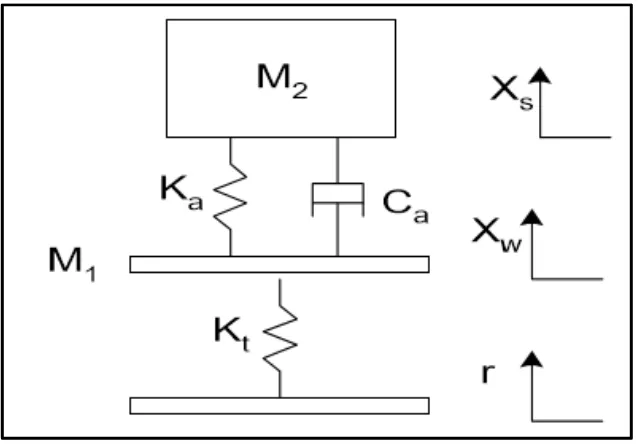
𝑀1 - mass of the wheel/unsprung mass (kg) 𝑀2 - mass of the car body/sprung mass (kg)
𝑟 - road disturbance/road profile
𝑋𝑤 - wheel displacement (m)
𝑋𝑠 - car body displacement (m)
𝐾𝑎 - stiffness of car body spring (Nm/s)
𝐾𝑡 - stiffness of tire (N/m)
𝐶𝑎 - damper (Ns/m)
𝑈𝑎 - force actuator
𝑋1=Xs− Xw - suspension travel
Ẋs - car body velocity
𝑋2=Ẍs - car body acceleration 𝑋3 = Xw− r - wheel deflection
𝑋̇𝑤 - wheel velocity
LIST OF APPENDICES
APPENDIX TITLE PAGE
A K-map of the suspension system 51
B Gantt Chart 52
C Coding 54
CHAPTER 1
INTRODUCTION
1.1 Motivation
The need of suspension for vehicle is important due to safety aspect, ride comfort and good vehicle handling. Suspension system has the facility to minimize vibration due to road roughness or uneven road profile because this suspension system will seclude passenger from vibration and shocks arising from road roughness. Suspension comprises of the arrangement of springs, shock absorbers and linkages that link a vehicle to its wheels. The suspension system also can secure the vehicle itself and any payload or luggage from damage and wear. There are two types of suspension system which is passive suspension and active suspension. A passive suspension system store energy through spring and dissipate it by a damper because there is no energy supplied by the suspension component to the system. While, the ability of an active suspension system is to store, dissipate and to supply energy to the system because it has force actuator.
1.2 Problem Statement
regulation case control.
1.3 Objective
This project embarks into following objectives:
1. To derive a mathematical model of active suspension system for a quarter-car model. 2. To design a Linear Quadratic Regulator (LQR) for active suspension control in order
to stabilize the vehicle's attitude.
3. To analyse the transient performance (settling time and overshoot) of LQR-based active suspension control that reflect the improvement of ride comfort, car handling and vibration minimization due to road roughness or uneven road profile.
1.4 Scope
This project focuses on a quarter-car suspensions system. The proposed controller is a state-feedback type for regulation case where the states are assumed available for feedback. The feedback gain of the closed-loop control is obtained by using LQR. The results are obtained via the simulation works using MATLAB with SIMULINK® toolbox. Thus, this project requires no hardware part.
1.5 Thesis Outline
In general, this thesis is divided into five chapters:
Chapter 1: Introduction
about the background of study which is related to the project.
Chapter 3: Research Methodology
Chapter 3 discusses about the methodology adopted for this research project. This chapter explain the overall process that has been conducted to complete this project.
Chapter 4: Results and Discussions
Chapter 4 shows the result obtained from data presented. The related parameters are arranged tidily using the aid of figures and tables. Hence, all the result is explained and compared. Then the comparison will be discussed.
Chapter 5: Conclusion and Recommendation
CHAPTER 2
LITERATURE REVIEW
2.1 Introduction
This chapter reviews related work on the project. This chapter consists of review on the system dynamics and models, review on the controllers and the conclusion of the research. The reviews are the most important parts because all the information from the research about the project is used as a reference to complete this project. All the review has been done by various source such as journal, book, website and others.
2.2 System Dynamics and Models
2.2.1 Vehicle model
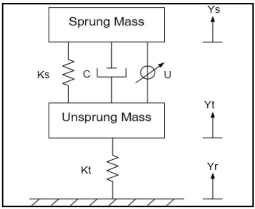
Figure 2.1: Quarter-Car model for an active suspension system.
2.2.1.1 Quarter-car model
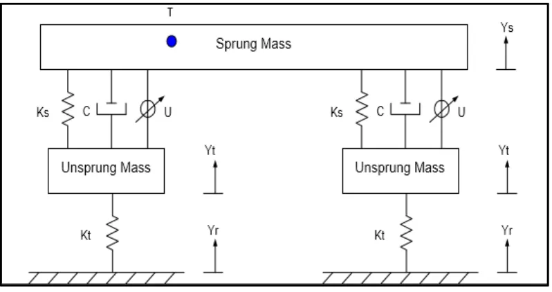
Figure 2.2: Half-Car model for an active suspension system.
1.1.1.1 Half-car model
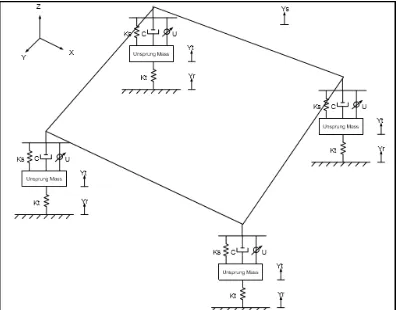
Figure 2.3: Full-Car model for an active suspension system.
2.2.1.3 Full-car model
The full car model can be designed by adding the link between the sprung mass to another four unsprung masses (body - front left and right, back left and right). Commonly, the link between sprung and unsprung masses will gave pitch and roll angle [11]. The basic modelling is still the same however there is extra thought about the bouncing, pitching and rolling need to be counted. The full-car suspension model represented as 7 DOF due to the haul, roll, and pitch movements of the sprung mass and the vertical movements of the unsprung masses, as depicted in Figure 2.3 [12].
2.2.2 Suspension system
contact with the road and controlling the direction of vehicle travel [13]. The suspension system normally divided into three categories which is passive suspension, semi-active suspension and active suspension. The main component use to designing the suspension system is a spring and parallel damper.
2.2.2.1 Passive suspension
[image:24.595.146.465.483.707.2]A passive suspension system consists of springs and dampers. A passive suspension system can be found in controlling the elements of vertical movement of a vehicle. The advantage of passive suspension is economically and simple to design, while the main drawback is its limit of suppressing the vibration occurring due to road roughness. Besides that, another drawback of passive suspension system is it has fix characteristic [14]. Even though it does not apply energy to the system, but it controls the relative motion of the body to the wheel by using different types of damping or energy dissipating elements. Passive suspension has significant limitation in structural applications. Figure 2.4 shows the components of passive quarter-car model that consists of spring and damper [15].


