Int. J. Electrochem. Sci., 8 (2013) 2417 - 2429
International Journal of
ELECTROCHEMICAL
SCIENCE
www.electrochemsci.org
Electrochemical Properties of 0.6Li
2MnO
3-0.4Li(Ni
1/3Mn
1/3Co
1/3)O
2Composite Cathode Powders with
Spherical Shape and Fine Size
Mun Yeong Son, Jung Hyun Kim, Yun Chan Kang*
Department of Chemical Engineering, Konkuk University, 1 Hwayang-dong, Gwangjin-gu, Seoul 143-701, Korea
*
E-mail: yckang@konkuk.ac.kr
Received: 19 December 2012 / Accepted: 14 January 2013 / Published: 1 Febraury 2013
0.6Li2MnO3-0.4Li(Ni1/3Mn1/3Co1/3)O2 composite cathode powders are prepared by spray pyrolysis. The spherical shape of the precursor powders are maintained after post-treatment at temperatures between 600 and 900°C. The grain growth in the powders increases with increasing post-treatment temperatures. The BET surface area of the composite cathode powders post-treated at 800°C is 7 m2 g−1. The discharge capacity of the cathode powders post-treated at 800°C decreases from 274 mAh g−1 to 242 mAh g−1 by the 50th cycle, the capacity retention being 88.3%. However, the discharge capacity of the powders post-treated at 700°C decreases from 247 mAh g−1 to 201 mAh g−1 by the 9th cycle. A high amount of Li2MnO3 in composite powders post-treated at high temperatures improves their cycle properties even at a high cutoff voltage of 4.8 V.
Keywords: composite materials;chemical synthesis;electrochemical properties;nanostructures
1. INTRODUCTION
Layered Li(Ni1/3Mn1/3Co1/3)O2 (NMC) has attracted considerable attention as a cathode material because of the merits of Mn-containing electrode materials [1-6]. Li(Ni1/3Mn1/3Co1/3)O2 and related compounds constitute a class of promising cathode materials because of their high specific capacities, low cost, and environmental friendliness [7,8]. In spite of these advantages, only about 50– 60% of the theoretical capacity of these compounds can be utilized in practical cells because of structural and chemical instabilities.
(a net loss of Li2O), typically at voltages in the range 4.6–4.8 V, forming a layered MnO2 component [11,14]. In particular, Li-rich NMC materials have been reported to be very promising because of their high capacities [11-13]. Electrodes containing these Li-rich NMC compositions can operate at high anodic potentials of 4.9 V vs. Li/Li+ and provide capacities higher than 250 mAh g−1 [11].
To improve the electrochemical properties of composite cathode materials, the dispersion of the layered Li2MnO3 phase in the layered LiMO2 matrix is required to be uniform and fine [15,16]. Furthermore, the characteristics of the composite cathode materials are strongly affected by the methods used to prepare the cathode powders [15-21]. The solid-state reaction method has a drawback in the preparation of the composite powders with uniform composition. Zheng et al. prepared Li-rich NMC cathode powders by using the coprecipitation (CP), sol-gel (SG), and sucrose combustion (SC) methods and showed that preparation methods strongly affected the morphological and electrochemical properties of the prepared powders [11].
Spray pyrolysis is a useful simple method for preparing highly pure cathode powders with fine-size and spherical shape [22-29]. Therefore, spray pyrolysis will has the advantages in the preparation of multicomponent composite cathode powders with uniform dispersion of the layered Li2MnO3 phase in the layered LiMO2 matrix. However, spray pyrolysis has not been well applied in the preparation of the layered-layered composite cathode powders. In this study, precursor powders for 0.6Li2MnO3-0.4Li(Ni1/3Mn1/3Co1/3)O2 were prepared by spray pyrolysis. The electrochemical properties of the composite powders post-treated at temperatures between 600°C and 900°C were investigated.
2. EXPERIMENTAL
0.6Li2MnO3-0.4Li(Ni1/3Mn1/3Co1/3)O2 composite cathode powders were prepared by ultrasonic spray pyrolysis. A 1.7-MHz ultrasonic spray generator with six vibrators was used to generate a large amount of droplets. The inner diameter and length of the quartz reactor in this generator were 55 mm and 1.2 m, respectively. The reactor temperature was maintained at 900°C. The flow rate of the air used as the carrier gas was fixed at 20 L min−1. Precursor powders prepared by spray pyrolysis were post-treated in air atmosphere at temperatures between 600 and 900°C for 5 h. The precursor solution was prepared by dissolving LiNO3 (Junsei, 98%), Ni(NO3)2∙6H2O (Junsei, 98%), Mn(NO3)2∙6H2O (Junsei, 97%), and Co(NO3)2∙6H2O (Junsei, 98%) in distilled water. The lithium component in excess of 3% weight of the stoichiometric amount was added to a spray solution. The overall concentration of Li, Ni, Mn, and Co components in the spray solution was 0.5 M.
the anode electrode and the separator, respectively. The electrolyte used was 1 M LiPF6 in a 1:1 mixture by volume of ethylene carbonate (EC) and dimethyl carbonate (DMC). The charge/discharge characteristics of the samples were measured by cycling them in the 2.0–4.8 V potential range at a constant current density of 25 mA g−1 by using a coin cell (2032 type).
[image:3.596.151.447.205.424.2]3. RESUTLS AND DISCUSSION
Figure 1. SEM image of precursor powders prepared by spray pyrolysis.
[image:3.596.135.465.487.731.2]
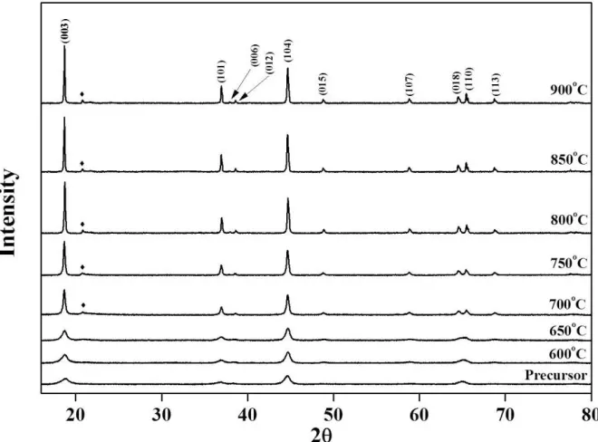
The morphology of the precursor powders prepared by spray pyrolysis is shown in Fig. 1. The precursor powders contained micrometer-sized spherical grains. The precursor powders were post-treated at temperatures between 600°C and 900°C to obtain layered-layered composite powders. Fig. 2 shows the XRD patterns of the precursor and post-treated cathode powders. The precursor powders showed a layered crystal structure similar to that of LiMO2. However, the precursor powders and the powders post-treated at low temperatures (below 700°C) showed low intensity ratios for the (003) and (104) peaks. The intensity ratios for the (003) and (104) peaks corresponding to the layered cathode materials indicate the degree of the anti-site mixing of Ni and Li [30-32]. The intensity ratios for the (003) and (104) peaks in the XRD patterns increased with increasing post-treatment temperatures up to 900°C. The intensity ratios for the (003) and (104) peaks corresponding to the cathode powders post-treated at 700°C, 800°C, and 900°C were 1.26, 1.45, and 1.62, respectively.
(a) 600℃
(c) 800℃
[image:5.596.151.445.65.543.2](d) 900℃
Figure 3. SEM images of composite cathode powders post-treated at various temperatures.
maintained the spherical shape of the precursor powders, irrespective of the post-treatment temperature. However, the grain growth in the powders increased with increasing post-treatment temperatures. The BET surface areas of the cathode powders decreased with post-treatment temperatures (see Table 1).
Table 1. Properties of the composite cathode powders post-treated at various temperatures. Temperature BET Surface Area
(m2 g-1)
Initial Discharge Capacity (mAh g-1)
Coulombic Efficiency (%)
600oC 35 234 81.4
700oC 15 247 79.0
800oC 7 274 83.9
900oC 4 254 79.6
Figure 4. Initial charge/discharge curves for composite cathode powders post-treated at various temperatures at a constant current density of 25 mA g−1 between 2.0 and 4.8 V.
[image:6.596.85.499.244.587.2][image:7.596.136.438.180.541.2]
component [11-13,17]. The initial discharge capacities and the Coulombic efficiencies of the first cycles were affected by the post-treatment temperatures of the composite cathode powders (see Table 1). The optimum post-treatment temperature was 800°C to obtain the composite cathode powders with high initial discharge capacity and the high Coulombic efficiency of the first cycle. The differential capacity vs. voltage (dQ/dV) curves for the first cycles are shown in Fig. 5.
Figure 5. Initial differential capacity vs. voltage curves for composite cathode powders post-treated at various temperatures.
The initial dQ/dV curves showed two distinct oxidation peaks at around 3.8 and 4.6 V. The peak at around 3.8 V is due to the oxidation of Ni2+ to Ni4+. The peak at around 4.6 V is due to the irreversible reaction involving the removal of Li and O as Li2O from Li2MnO3 [17]. The peak intensity of the oxidation peak at around 4.6 V increased with increasing post-treatment temperatures. A high amount of layered Li2MnO3 material was formed at the high post-treatment temperatures of 800°C and 900°C. Mn has been shown to exist as Mn4+
The reduction peak intensities are similar regardless of the post-treatment temperature of the composite cathode powder. When the MnO2 formed from Li2MnO3 had a large grain size or a large crystallite size, Mn4+ transformed gradually into Mn3+ from the surface of the grain or crystallite and participated in the electrochemical reaction, according to the cycle numbers. Therefore, the composite powders post-treated at low temperatures with low amounts of the Li2MnO3 phase showed peak intensities of the Mn4+/Mn3+ redox reactions similar to those of powders post-treated at high temperatures with high Li2MnO3 contents in the first cycles. The decomposition of the composite powders started at a high temperature of 900°C. Therefore, the composite powders post-treated at 800°C had larger initial discharge capacity than that of the powders post-treated at 900°C.
Figure 6. Cycle properties of composite cathode powders post-treated at 800°C at a constant current density of 25 mA g−1 between 2.0 and 4.8 V.
[image:8.596.111.475.249.512.2]
ions in the layered Li(Ni1/3Mn1/3Co1/3)O2 cathode material [36].
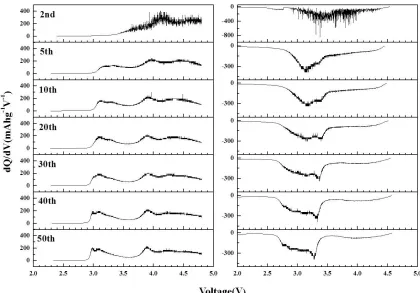
Figure 7. Differential capacity vs. voltage curves after the second cycle for composite cathode powders post-treated at 800°C.
Therefore, no oxidation and reduction peaks of the Mn ions were observed in the first and second dQ/dV curves in Figs. 5 and 7. The distinct oxidation (Mn3+ to Mn4+) and reduction (Mn4+ to Mn3+) peaks of the Mn ions were observed beginning in the 5th charging and discharging curves below 3.5 V. The inactive MnO2 formed by leaching of Li2O from the Li2MnO3 component in the first charging process was activated to form layered LiMnO2 cathode material in the following discharge processes [41]. The layered LiMnO2 gradually transformed into spinel LiMn2O4 as the cycle number increased to 10 cycles [42]. Therefore, the reduction and oxidation peaks of the Mn ions shift to low-voltage regions in the charging and discharging curves as the cycle number increases. However, the shapes of the dQ/dV curves slightly changed after 10 cycles, as shown in Fig. 7. Therefore, the prepared composite cathode powders had high capacity retention after cycling at a high cutoff voltage of 4.8 V.
[image:9.596.79.499.117.410.2]
at 700°C are shown in Fig. 9.
Figure 8. Cycle properties of composite cathode powders post-treated at 700°C at a constant current density of 25 mA g−1 between 2.0 and 4.8 V.
[image:10.596.157.429.108.306.2] [image:10.596.178.410.379.703.2]
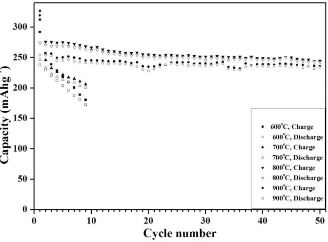
Figure 10. Cycling performance of composite cathode powders post-treated at various temperatures at a constant current density of 25 mA g−1 between 2.0 and 4.8 V.
The reduction peaks of the Mn ions clearly shift to the low-voltage regions in the dQ/dV curves as the cycle number increases. Rapid transformation of the layered LiMnO2 to spinel LiMn2O4 occurred. The stabilization effect of the Li2MnO3 phase was poor in the composite powders post-treated at 700°C. The poor cycle property was also due to the high surface area and low crystallinity of the composite powders post-treated at 700°C.
Fig. 10 shows the cycle properties of the 0.6Li2MnO3-0.4Li(Ni1/3Mn1/3Co1/3)O2 cathode powders post-treated at various temperatures. The charge and discharge capacities of the cathode powders post-treated at 600°C and 700°C abruptly decreased within several cycles. On the other hand, the cathode powders post-treated at 800°C and 900°C had good cycle properties even after 50 cycles. The high amount of the Li2MnO3 phase in the composite powders post-treated at high temperatures improved the cycle properties even at a high cutoff voltage of 4.8 V.
4. CONCLUSIONS
ACKNOWLEDGEMENT
This work was supported by the National Research Foundation of Korea (NRF) grant funded by the Korea government (MEST) (No. 2012R1A2A2A02046367). This research was supported by Basic Science Research Program through the National Research Foundation of Korea (NRF) funded by the Ministry of Education, Science and Technology (2012R1A1B3002382). This work was supported by Seoul R&BD Program (WR090671).
References
1. L. Yu, W. Qiu, F. Lian, J. Huang, X. Kang, J. Alloys Compd., 471 (2009) 317. 2. N. Yabuuchi, T. Ohzuku, J. Power Sources, 119–121 (2003) 171.
3. S. Patoux, M.M. Doeff, Electrochem. Commun., 6 (2004) 767.
4. D.C. Li, T. Muta, L.Q. Hang, M. Yoshio, H. Noguchi, J. Power Sources, 132 (2004) 150. 5. H.C. Wu, Z.Z. Guo, M.H. Yang, C.H. Lu, T.Y. Wu, I. Taniguchi, Chem. Lett., 34 (2005) 1398. 6. Z. Bakenov, I. Taniguchi, Solid State Ionics, 176 (2005) 1027.
7. J.H. Lim, H. Bang, K.S. Lee, K. Amine, Y.K. Sun, J. Power Sources, 189 (2009) 571.
8. X.J. Guo, Y.X Li, M. Zheng, J.M. Zheng, J. Lie, Z.L. Gong, Y. Yang, J. Power Sources, 184 (2008) 414.
9. K.M. Shaju, G.V. Subba Rao, B.V.R. Chowdari, Electrochim. Acta, 48 (2002) 145. 10.J.L. Liu, J. Wang, Y.Y. Xia, Electrochim. Acta, 56 (2011) 7392.
11.J.M. Zheng, X.B. Wu, Y. Yang, Electrochim. Acta, 56 (2011) 3071.
12.S.J. Jin, K.S. Park, C.H. Song, M.H. Cho, K.S. Nahm, Y.B. Hahn. Y.S. Lee, J. Power Sources, 146 (2005) 630.
13.C. Gan, H. Zhan, X. Hu, Y. Zhou, Electrochem. Commun., 7 (2005) 1318.
14.D.K. Lee, S.H. Park, K. Amine, H.J. Bang, J. Parakash, Y.K. Sun, J. Power Sources, 162 (2006) 1346.
15.F. Wu, H. Lu, Y. Su, N. Li, L. Bao, S. Chen, J. Appl. Electrochem., 40 (2010) 783. 16.P.S. Whitfield, S. Niketic, I.J. Davidson, J. Power Sources, 146 (2005) 617.
17.C.S. Johnson, J.S. Kim, C. Lefief, N. Li, J.T. Vaughey, M.M. Thackeray, Electrochem. Commun., 6 (2004) 1085.
18.B.L. Ellis, K.T. Lee, L.F. Nazar, Chem. Mater., 22 (2010) 691.
19.J.S. Kim, C.S. Johnson, J.T. Vaughey, M.M. Thackeray, J. Power Sources, 153 (2006) 258. 20.H. Deng, I. Belharouak, R.E. Cook, H. Wu, Y.K. Sun, K, Amine, J. Electrochem. Soc., 157 (2010)
A447.
21.T. Ohzuku, M. Nagayama, K. Tsuji, K. Ariyoshi, J. Mater. Chem., 21 (2011) 10179.
22.S.H. Park, C.S. Yoon, S.G. Kang, H.S. Kim, S.I. Moon, Y.K. Sun, Electrochim. Acta, 49 (2004) 557.
23.S.H. Choi, J.H. Kim, Y.N. Ko, Y.J. Hong, Y.C. Kang, J. Power Sources, 210 (2012) 110. 24.I. Taniguchi, C.K. Lim, D. Song, M. Wakihara, Solid State Ionics, 146 (2002) 239.
25.Y.N. Ko, H.Y. Koo, J.H. Kim, J.H. Yi, Y.C. Kang, J.H. Lee, J. Power Sources, 196 (2011) 6682. 26.I. Taniguchi, D. Song, M. Wakihara, J. Power Sources, 109 (2002) 333.
27.S.H. Park, Y.K. Sun, Electrochim. Acta, 50 (2004) 431.
28.Y.N. Ko, J.H. Kim, Y.J. Hong, Y.C. Kang, Mater. Chem. Phys., 131 (2011) 292. 29.K. Matsuda, I. Taniguchi, J. Power Sources, 132 (2004) 156.
30.S. Yamada, M. Fujiwara, M. Kanda, J. Power Sources, 54 (1995) 209.
31.T. Ohzuku, A. Ueda, M. Nagayama, Y. Iwakoshi, H. Komori, Electrochim. Acta, 38 (1993) 1159. 32.J. Morales, C. Pérez-Vicente, J.L. Tirado, Mater. Res. Bull., 25 (1990) 623.
34.M.M. Thackeray, S.H. Kang, C.S. Johnson, J.T. Vaughey, R. Benedek, S.A. Hackney, J. Mater. Chem., 17 (2007) 3112.
35.Z. Lu, Z. Chen, J.R. Dahn, Chem. Mater., 15 (2003) 3214. 36.J.M. Kim, H.T. Chung, Electrochim. Acta, 49 (2004) 3573.
37.S.K. Kim, W.T. Jeong, H.K. Lee, J.P. Shim, Int. J. Electrochem. Sci., 3 (2008) 1504. 38.G. Ting-Kuo Fey, C.S. Chang, T. Prem Kumar, J Solid State Electrochem., 14 (2010) 17.
39.Y.J. Shin, W.-J. Choi, Y.-S. Hong, S. Yoon, K.S. Ryu, S.H. Chang, Solid State Ionics, 177 (2006) 515.
40.N. Yabuuchi, Y. Makimura, T. Ohzuku, J. Electrochem. Soc., 154 (2007) A314. 41.Z. Lu, J.R. Dahn, J. Electrochem. Soc., 149 (2002) A815.