This is a repository copy of
Split ratio optimisation of high-speed permanent magnet
brushless machines considering mechanical constraints
.
White Rose Research Online URL for this paper:
http://eprints.whiterose.ac.uk/146799/
Version: Accepted Version
Article:
Feng, J., Wang, Y., Guo, S. et al. (3 more authors) (2019) Split ratio optimisation of
high-speed permanent magnet brushless machines considering mechanical constraints.
IET Electric Power Applications, 13 (1). pp. 81-90. ISSN 1751-8660
https://doi.org/10.1049/iet-epa.2018.5051
This paper is a postprint of a paper submitted to and accepted for publication in IET
Electric Power Applications and is subject to Institution of Engineering and Technology
Copyright. The copy of record is available at the IET Digital Library.
[email protected] https://eprints.whiterose.ac.uk/ Reuse
Items deposited in White Rose Research Online are protected by copyright, with all rights reserved unless indicated otherwise. They may be downloaded and/or printed for private study, or other acts as permitted by national copyright laws. The publisher or other rights holders may allow further reproduction and re-use of the full text version. This is indicated by the licence information on the White Rose Research Online record for the item.
Takedown
If you consider content in White Rose Research Online to be in breach of UK law, please notify us by
1
Split Ratio Optimization of High Speed Permanent Magnet Brushless Machines
Considering Mechanical Constraints
Jianghua Feng
2, Yu Wang
1, Shuying Guo
2, Zhichu Chen
2, Yu Wang
2, Zi-Qiang Zhu
1*1Department of Electronic and Electrical Engineering, University of Sheffield, Mappin Street, Sheffield,UK 2CRRC Zhuzhou Institute Co. Ltd, Shidai Road, Shifeng District, Zhuzhou, Hunan, People’s Republic of China *[email protected]
A The split ratio of rotor outer diameter to stator outer diameter is one of the most important design parameters due to its significant impact on machine torque density and efficiency. It has been optimized analytically in existing papers with due account given only for the thermal limitations. In this paper, the optimized split ratio for high speed PM machines (HSPMM) with consideration of the mechanical constraints is investigated analytically. In addition, the influences of flux density ratio, maximum operating speed and sleeve material on the optimized split ratio are discussed in detail. The analytical results are verified by finite element analyses. It is demonstrated that the optimized split ratio as well as the achievable torque of HSPMM is significantly reduced when the mechanical constraints are taken into consideration. The experimental results on a 6/slot-4pole HSPMM confirm the validity of previous analyses.
1. Introduction
High-speed electrical machines have been widely used in a variety of applications including domestic appliances, electrical spindles, turbochargers, electrical turbo-compounding systems, and have been attracting increased interest from both industry and academia, particularly in the last two decades [1]-[4].
As a competent candidate, high-speed permanent magnet (PM) machine (HSPMM) is a very promising design alternative for high-speed applications due to high power density as well as high efficiency and compactness compared with other types of electrical machines such as induction machines and switched reluctance machines [5]-[9].
However, there are still many challenges for machine designers to overcome. Compared with low-to-medium speed PM machines, one of the most significant design considerations is the mechanical issue. Under high-speed operation, the rotor components will suffer huge centrifugal stress, making the magnet retaining extremely important [10]. The centrifugal stress is influenced by a few factors, including the rotor diameter. On the other hand, the split ratio, the rotor outer diameter to the stator outer diameter, is also an important design parameter for any PM machine. It has a great impact on the torque/power capability and efficiency for the given frame size. [11] derived a simple analytical expression of optimum split ratio for maximum torque density. In [12], the optimal split ratio of both brushless AC and DC motors with either overlapping or non-overlapping windings were investigated. In addition, the influences of air gap flux density waveforms, stator tooth-tips as well as the end-winding on the optimal split ratio were discussed. In [13], the optimal split ratio as well as the flux density ratio were analysed both individually and globally in a fractional-slot IPM machine.
For HSPMM, the design of the split ratio is even more important. Not only is the torque density of HSPMM significantly influenced by this parameter, but also the mechanical stress of the rotor and stator iron loss are greatly
impacted by this ratio. Hence, it is necessary to investigate the optimal split ratio for HSPMM. In [14], the stator iron loss was considered in the analysis of optimal split ratio of a high speed PM machine. It was found that the optimal split ratio is slightly reduced compared to that with a fixed copper loss only. [15] introduced the current density as the local thermal constraint which is reasonable only when considering the local overheat in stator end-windings [16]. In [17], the thermal network was adopted in order to obtain the winding temperature rise of HSPMM directly and a more accurate value of optimal split ratio could be acquired. However, compared with the stator temperature, the temperature rise in the rotor should be more of a concern for HSPMM since the permanent magnets are vulnerable to the temperature rise resulting from the induced PM eddy-current loss.
In summary, in existing papers, the split ratio of HSPMM has been optimized with the consideration of thermal constraints only. The mechanical constraints, including the stress limit and rotor dynamics issues are ignored, leading to the deviation of the optimal split ratio and actual torque/power capability. In this paper, the optimized split ratio for HSPMM is obtained with the consideration of the mechanical constraints, with particular focus on the rotor stress. The impact of the sleeve material and maximum operating speed on the optimized split ratio is elaborated. In addition, the influence of the flux density ratio, i.e. the ratio of airgap flux density to stator lamination flux density on the optimized split ratio is analysed.
2 performances are experimentally validated in section 5, with
the conclusions in section 6.
2. Optimized Split Ratio For Maximum Torque
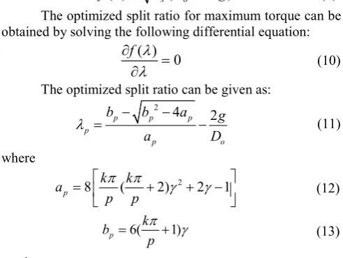
Fig. 1(a) illustrates a typical cross-section of HSPMM. Generally, when the air gap flux distribution is uniform and the armature reaction is ignored, the electromagnetic torque of a three-phase brushless PM motor can be expressed as [12][18]:
3 2
2 s a w w a g
T D l N k I B (1)
where Ds is the stator bore diameter. la is the active stack length and Nw represents the serial turns of each phase. kw denotes the winding factor. Ia is the RMS of the phase current and Bg is the air gap flux density. It should be noted that the split ratio for HSPMM in this paper refers to the ratio of rotor outer diameter to stator outer diameter which is different from definitions for low-speed electrical machines. The influence of air gap length on optimized split ratio for HSPMM is significant and will be addressed in this section. Hence, denotes the split ratio which is defined as:
r
o
D
D
(2)where Dr is the rotor outer diameter and Do is the stator outer diameter. The stator bore diameter can be expressed as:
2
s o
D
D g (3)where g denotes the total air gap length. The torque can be further given as [12]:
3 2 ( 2 )
2 s o cu s36 s a w g
cu
P k N l
T A D g k B
(4)
where As is the slot area and ks is the slot packing factor. Ns is the slot number and cu is the resistivity of copper. On the other hand, ignoring the effect of saturation, flux-leakage as well as slotting effect, the air gap flux density Bg can be accordingly expressed as [19]:
m
g r
m
h
B B
h g
(5)
where hm is the PM thickness. When (5) is substituted into (4), the electromagnetic torque can be derived as:
3 2 ( 2 )
2 s o m r w cu s36 s a
m cu
h P k N l
T A D g B k
h g
(6)
Where
2 2
2
2
( ) ( 2) 2 1
3 3
4 2( 2 )( 1) 1
3
o o
s s
o
g
D p p
D A
N g
D p
(7)
where p is the rotor pole pairs and Ns denotes the stator slot number and represents the flux density ratio which is defined as:
max
g
B B
(8)where Bmax is the maximum flux density in the stator iron. Hence, the electromagnetic torque with respect to the split ratio can be expressed as:
( )
s(
o2 )
T
f
A D
g
(9) The optimized split ratio for maximum torque can be obtained by solving the following differential equation:( ) 0
f
(10)The optimized split ratio can be given as: 2 4
2
p p p
p
p o
b b a g
a D
(11)where
2
8 ( 2) 2 1
p k k
a
p p
(12)
6( 1)
p k
b p
(13)
1
3
k for motors with stator non-overlapping winding (14) While the split ratio increases, the tooth width and yoke thickness will become larger correspondingly when the air gap length and the flux density ratio are confirmed. The resultant slot area will decrease with the increase of split ratio. Hence, there will always exist an optimized split ratio at which the electromagnetic torque reaches maximum. The minimum air gap length (g=2mm) is obtained with the usage of the empirical equation in [20]. A suitable value for the length of the air gap of an inverter fed, high-speed machine (the peripheral speed of the rotor>100 m/s), can be calculated as:
0.001
0.07 400r
D v
(15)
Where Dr denotes the rotor outer diameter and v denotes the peripheral speed of the rotor.
The copper loss is fixed so as to ensure the same thermal performance. As for the value of copper loss, when the machine frame size is given, the total heat transferred through the external surface depends on the specific cooling type. This heat source, namely electromagnetic loss, can be written as [3]:
limit m o a
P h D l (16)
where h denotes the thermal heat transfer coefficient and m denotes the maximum allowed temperature corresponding to specific insulation level.
On the other hand, the range of feasible split ratio is significantly limited by the geometrical restrictions. The maximum split ratio depends on the air gap length and flux density ratio when the stator outer diameter is given.
Fig. 1(b) shows the variation of torque with split ratio and air gap length. It can be seen that the optimized split ratio for maximum torque is significantly reduced with the increase of flux density ratio. This can be attributed to the increase of stator teeth and back iron due to larger flux density ratio. Thus, the slot area is accordingly reduced. The split ratio is then reduced to make up for the shrink of space so that the copper loss can be constant.
[image:3.595.308.554.71.256.2] [image:3.595.41.287.381.654.2]3 the variation of torque versus split ratio with respect to different air gap length. It can be seen that the optimized split ratio will be significantly reduced with the increase of air gap length when the flux density ratio is constant. The slot area is reduced with the increase of air gap length. The split ratio will accordingly be reduced in order to keep the copper loss constant. Fig. 1(d) shows the variation of analytical and FE calculated electromagnetic torques with split ratio, for the machine having a 6s/4p (Ns/2p) with a non-overlapping winding. It should be noted that the stator and rotor iron permeability is assumed infinite and the flux leakage is ignored in the analytical results. It can be seen that the analytical result agrees well with the FE predicted one.
3. Split Ratio Optimization For HSPMM Under Mechanical Constraints
The topology of HSPMM is similar to low-to-medium speed operating PM machines. In [9], it is highlighted that due to the requirement of mechanical robustness and thermal stability, a surfaced mounted permanent magnet (SPM) machine with a high-strength retaining sleeve is almost exclusively employed.
To obtain certain pre-stress between the sleeve and PM at high speeds, an interference fit should always exist between the PM and the sleeve so that the contact force and circumferential force in the sleeve can be derived for magnet retaining. In addition, to avoid the presence of stress concentration at the magnet edges, the inter-pole air gap between magnets should be avoided [10].
At the preliminary design stage, it is of vital importance to take the mechanical constraints into consideration. Generally, two fundamental conditions should be satisfied: the circumferential stress in the inner surface of the sleeve should be within the material limits, and the contact pressure between PM and rotor back-iron should always be positive [10].
For HSPMMs, the optimized split ratio is inevitably influenced by the aforementioned mechanical constraints. Both the circumferential tensile stress and contact pressure are highly related to the rotor diameter which can be reflected by the split ratio.
3.1. Split Ratio Optimization with
Circumferential Stress Limitation
In most cases, the PMs in a HSPMM are more vulnerable to the tensile stress than the compressive stress. Both NdFeB and SmCo have strong compressive strength and flexural strength but are very weak in tensile strength. Hence, a retaining sleeve with strong circumferential tensile strength is necessary. In fact, the main stress in the retaining sleeve is in the form of circumferential stress which, when the sleeve is considered as the thin shell, can be expressed as [10]:
, ,
2 2 2
1 4 t t prestress t w
b o
o
DE w D
D
(17)
a
b
c
[image:4.595.55.261.66.641.2]d
Fig. 1. Electromagnetic torque versus split ratio (p=2, Ns=6, Do=90mm, la=55mm, copper loss=100W
=0.5)
(a) Typical cross-section of high-speed PM machines (6 slots and 4 poles)
(b) Electromagnetic torque versus split ratio and air gap length with respect to different flux density ratio (c)Variation of electromagnetic torque with split ratio with respect to different air gap length (d) Analytically and FE predicted variations of torque with split ratio and air gap length
8 0
1
0.2 2 3
6 4
5 6
0.3 7 8 9
0.4 4
0.5 2 0.6 1
2 3 4 5 6 7 8 9
To
rq
ue
(N
m
)
0.6 0.2 0.3 0.4 0.5
2 4
6 8
0.5
1
0.75
0 2 4 6 8 10
0.2 0.3 0.4 0.5 0.6
Tor
qu
e (
N
m
)
Split ratio
4 where refers to the pre-stress due to shrinking of
retaining sleeve. denotes the additional circumferential stress due to rotation and is the total circumferential stress of the specific sleeve. is the sleeve interference fit with respect to the machine diameter . and E represent the sleeve mass density and the Young’s modules. is the angular velocity of the rotating rotor.
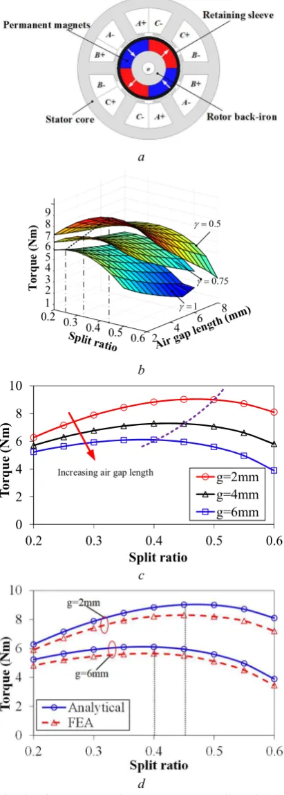
As can be seen from (17), the sleeve circumferential stress can be expressed as the function of split ratio. The value of circumferential stress depends on the sleeve material property (mass density and Young’s modules), the interference fit, the operating speed, as well as the split ratio. Fig. 2(a) illustrates the circumferential stress at the inner side of sleeve with the variation of different interference fits. It can be seen that the circumferential stress will increase with the increase of sleeve interference fit in the whole split ratio range. For each given sleeve interference fit, the circumferential stress will drop sharply with the increase of split ratio before reaching a minimum value. After that, the circumferential stress will rise slowly with the increase of split ratio.
For a given sleeve with certain circumferential strength, the split ratio can be flexibly chosen by adjusting the sleeve interference fit. However, there always exists a minimum split ratio for each sleeve interference fit at which the circumferential stress reaches the material limits. These minimum split ratios increase with the increase of sleeve interference fit. In addition, they are also influenced by the actual circumferential stress. For illustration, two limit lines representing different values of real sleeve circumferential stress are also shown in Fig. 2(a). It can be seen that when the actual sleeve circumferential stress reaches the material limit, the value of the minimum split ratio is the smallest. Hence, a factor k is defined to evaluate the stress margin with respect to the sleeve material tensile strength.
limit t
k
(18)where represents the actual value of sleeve circumferential stress and is the tensile strength limit of the sleeve material. Fig. 2(b) illustrates the relationship between the minimum split ratio and the interference fit as well as k. It should be noted that the maximum operating speed at which the circumferential stress is checked has been increased by 20% for the consideration of an over speed test [10]. It can be seen that the widest split ratio range can be achieved when the actual circumferential stress reaches the limits and the interference fit is relatively small. Hence, k is preferred to be 1 so that the design values for split ratio can be adequate.
3.2. Split Ratio Optimization with Contact Pressure Limitation
Generally, for a simple rotor configuration with symmetrically mounted magnets, the contact pressure between the magnets and the rotor back iron can be expressed as [10]:
, b
contact pressure t prestress m b b
h
P
p
p
r
(19)where hb and rb represent the thickness and average radius of selected sleeve. pm and pb represent the pressures of magnets
and sleeve resulting from centrifugal force which reduces the total contact pressure between the magnets and the rotor. These pressures can be analytically determined as [10]:
2
m m m m
p r h (20)
2
b b b b
p r h (21)
where hm and rm represent the thickness and average radius of PMs. m and b represent the mass densities of the magnets and sleeves. On the other hand, the sleeve pre-stress due to shrink fit can be expressed as the difference between the actual sleeve circumferential stress and the circumferential stress due to rotation. In addition, (20) and (21) can be substituted into (19). Hence, (19) can be further derived as a function of split ratio:
,
2
2 2
( )
2 1 (1 )
2 1
2 b
contact pressure t t w m b b
b t
m m b b o o
m m h
P p p
r
h h h D
D h
(22)
As mentioned in the previous section, the contact pressure between the rotor and the magnets should always be positive. From (22), it can be seen that the contact pressure decreases with the increase of split ratio. Hence, there exists a special split ratio at which the contact pressure
a
[image:5.595.318.529.57.360.2]b
Fig. 2. Typical Cross-section of HSPMM and split ratio optimization under circumferential stress limits
(a) Variation of sleeve circumferential stress with split
ratio (carbon fibre nmax=120kr/min)
(b) Minimum split ratio versus interference fit and factor k
(carbon fibre nmax=120kr/min)
0 1200 2400 3600 4800 6000
0.0 0.2 0.4 0.6 0.8 1.0
Tan
ge
nt
ia
l s
tr
es
s (
M
Pa
)
Split ratio
∆D=0.10mm ∆D=0.15mm ∆D=0.20mm ∆D=0.25mm ∆D=0.30mm ∆D=0.35mm Increasing ∆D
limit
t
limit
0.7
t
[image:5.595.312.549.617.695.2]5 equals zero and the actual split ratio should always be
smaller than this value. This can be expressed as: 2
16
2
o
a
a
c
b
(23)where
2
m m
a h (24)
2 2
(2 ) /
t b b m m b
b h h h (25)
(2 )
o b b m m
c D h h (26)
For HSPMM, the main component of the sleeve circumferential stress is the pre-stress due to shrink fit, especially for the carbon fibre sleeve with low mass density [10]. Compared with the circumferential stress ( ) resulting from sleeve shrinking, the circumferential stress due to rotation ( ) is much smaller. Therefore, the following condition can be applied:
2 2
2 2 2
,
16 16 (2
) /
16
(2
) /
t b b m m b
t w b b m m b
b
h
h h
h
h h
a
(27)Hence, (23) can be further simplified as:
limit
4 2 (0 1)
2 2 o m o b m b
b k k
h c D h
(28)
It has been proved that the feasible range of split ratio is the widest when k equal to 1. Hence, the maximum split ratio of HSPMM under contact pressure limit can be given as:
limit max 2 2 m o b m b h D h
(29)It can be seen that the split ratio of HSPMM is restricted by the sleeve tensile strength, the maximum operating speed as well as the magnet mass density and the ratio of magnet to sleeve thickness. The maximum split ratio is significantly reduced with the increase of maximum operating speed and the ratio of magnet to sleeve thickness.
On the other hand, it is obvious that the air gap of HSPMM is larger than that of normal PM machines due to existence of sleeve. From (29) the minimum air gap length, which consists of physical air gap and sleeve, can be given as:
min ,minlimit 2 2
( ) 4
1 2 m
b m
b o
g h h
D
(30)Clearly, the sleeve material in terms of mass density and tensile strength has a significant impact on the minimum sleeve thickness which will be fully addressed in the subsequent section. In this section, the sleeve material is selected to be carbon fibre due to its low mass density and high tensile strength. Ignoring the effect of saturation, flux-leakage as well as slotting effect, the air gap flux density can be accordingly expressed as:
limit
2 2 11 4 1 2
m
g r r
m m b m b o h
B B B
h h h D
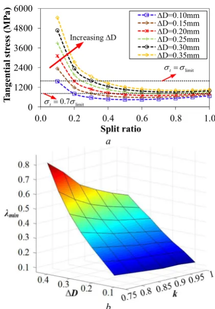
(31)Substituting (30) and (31) into (6), the electromagnetic torque of HSPMM under mechanical constraints can be derived as:
3 2
( )
( ) ( )
2
r w cu s36
s a cuP k N l
T
f
g B k
(32)where
limit
2 2 2( ) ( 4 2 )
1 2m
s o m
b o
f A D h
D
(33)
limit
2 21 ( )
1 4 m1 2 m b o g h D (34)
Hence, the optimized split ratio of HSPMM under mechanical constraints can be obtained by solving the equation as follows:
( ) 0
T
(35)It is apparent that the equation for the optimized split ratio considering the mechanical constraints is much more complicated than that of the normal PM machines due to the presence of g( ). The pure analytical solution of a high order equation (35) is quite complicated as well. Thus, the numerical method is adopted which is much easier and convenient to solve this equation. The two equations with respect to the electromagnetic and mechanical domains have already been determined as:
min
limit 2 2
3 2
( , ) ( 2 )
2 36
( )
4 1 2
m r cu s s a s
o w m cu m m b o
h B P k N l A
T g D g k
h g g h D
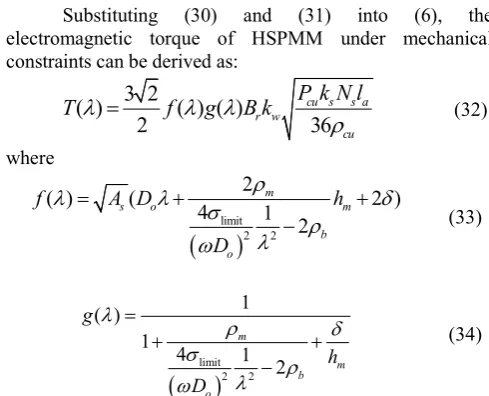
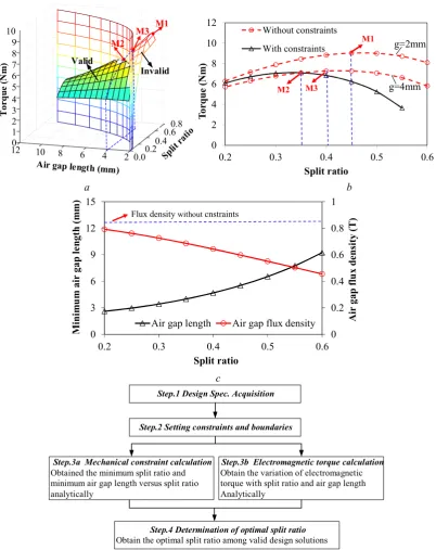
(36)Fig. 3(a) illustrates the surfaces of two equations in the electromagnetic and mechanical domain, respectively. The electromagnetic surface is divided into two parts by the surface representing the mechanical constraints. For each specific split ratio, there exists a corresponding minimum air gap length. Hence, the left-side of the electromagnetic surface is valid from the mechanical point of view. In addition, it is obvious that a curve is defined by the intersection of the two surfaces. This curve represents the enveloping of valid designs in the electromagnetic domain considering the mechanical constraints.
[image:6.595.306.551.55.253.2]6 optimized split ratio is further reduced to 0.35(M2). This
reduction can be attributed to the different level of limitation on the air gap flux density with the increasing of the split ratio.
Fig. 3(c) shows the minimum required air gap length and the corresponding maximum air gap flux density with increase of split ratio. It can be seen that the flux density is dramatically decreased due to the increased air gap length. This limitation becomes more obvious with the increase of split ratio when the PM thickness is given. Hence, the shift of optimized split ratio does not only result from the
increase of air gap length due to presence of the sleeve which has been proved in the previous section. More importantly, the restriction for the air gap flux density also varies with the split ratio. The difference between the restricted flux density with the unrestricted one becomes larger with the split ratio increasing. Thus, the optimized split ratio corresponding to the maximum torque has to be decreased. The maximum torque has also been decreased due to a reduction of the achievable air gap flux density. The optimization procedure for the optimized split ratio is shown in Fig. 3d.
a b
c
[image:7.595.97.500.62.570.2]d
Fig. 3. Optimized split ratio under mechanical constraints ( =0.5, p=2, =2mm, hm =8mm, nmax=120kr/min) (a) Variation of electromagnetic torque with split ratio and air gap length
(b) Variation of electromagnetic torque with variation of split ratio
(c) Variation of minimum air gap length and maximum air gap flux density with split ratio (d) Optimization procedure for split ratio of HSPMM considering mechanical constraints
0.00.2
0.40.6
0.8
2 4 6 8 10
120
1 2 3 4 5 8 9
7 6 10
To
rq
ue
(N
m
)
M1 M2
Valid
Invalid
M3
0 2 4 6 8 10 12
0.2 0.3 0.4 0.5 0.6
To
rq
ue
(N
m
)
Split ratio Without constraints With constraints
g=4mm M1
M2 M3
g=2mm
0 0.2 0.4 0.6 0.8 1
0 3 6 9 12 15
0.2 0.3 0.4 0.5 0.6
A
ir
gap
fl
ux
de
ns
ity
(T
)
M
in
im
um
ai
r gap
le
ngt
h
(m
m
)
Split ratio
Air gap length Air gap flux density
Flux density withoutcnstraints
Step.1 Design Spec. Acquisition
Step.2 Setting constraints and boundaries
Step.4 Determination of optimal split ratio
Obtain the optimal split ratio among valid design solutions
Step.3b Electromagnetic torque calculation
Obtain the variation of electromagnetic torque with split ratio and air gap length Analytically
Step.3a Mechanical constraint calculation
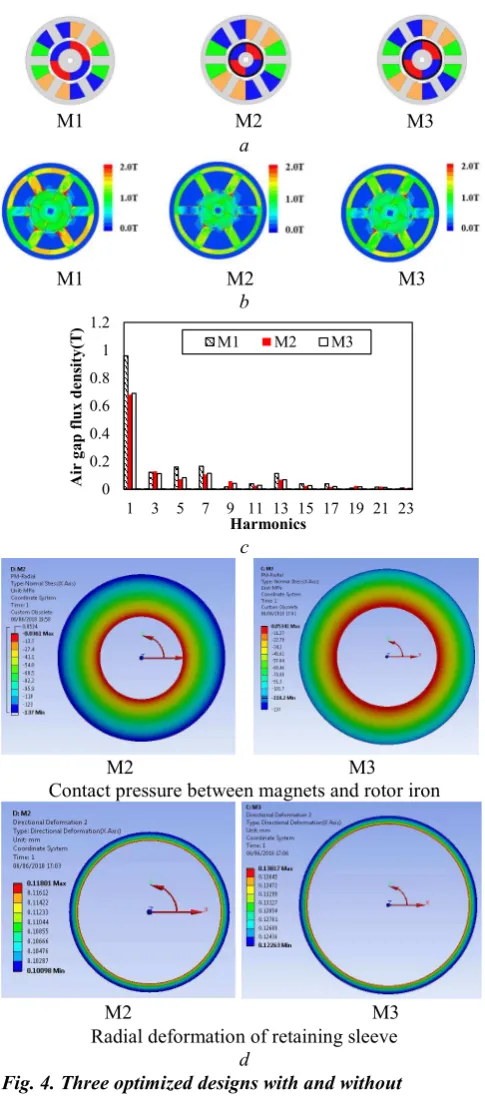
7 Fig. 4(a) shows the cross sections of the optimized
designs with and without consideration of mechanical
constraints. Clearly, the split ratio is significantly reduced. The design parameters of each machine are given in Table 1. Fig. 4(b) illustrates the flux distributions of optimized designs with or without the mechanical constraints. Evidently, the design with mechanical constraints (M2) exhibits less saturation in the stator iron than the one without mechanical constraints (M1) due to increase of air gap length. On the other hand, when the total effective air gap length keeps constant, the optimized design without mechanical constraint (M3) has a similar stator as well as air gap flux density compared with that with mechanical constraint (M2).
Fig. 4(c) illustrates the spectra of air gap flux densities of three optimized designs with and without consideration of mechanical constraints. Both M2 and M3 clearly exhibit much lower fundamental flux density than M1, which agrees well with the trend in Fig. 4(b).
The contact pressures between magnets and rotor back iron for two optimized designs are shown in Fig. 4(d). It should be noted that the absolute value of contact pressure represents the stress level. The negative sign represents the direction of contact pressure (points to centre in the polar coordinates system). It can be seen that the minimum contact pressure lies on the surface between the permanent magnet and the rotor back iron. The minimum contact pressure for the design without consideration of mechanical constraints (M3) is 0.053MPa, making the permanent magnets finally detach from the rotor back iron. Meanwhile, the contact pressure for the optimized design considering mechanical constraints (M2) is -0.036MPa which provides a residual force for permanent magnets sticking on the rotor back iron. To conclude, M2 proves to be the most feasible design solution with the maximum electromagnetic torque when the mechanical constraints are taken into consideration. The geometrical parameters of the designed HSPMM are shown in Table I. It should be noted that the geometrical parameters in Fig.1 are not the same with M2.
In addition, it should be noted that the thermal constraints in terms of stator iron loss as well as AC copper loss and rotor eddy-current loss also affect the split ratio of HSPMM due to the restriction of flux density. This will be studied in future research.
M1 M2 M3
a
M1 M2 M3
b
c
M2 M3
Contact pressure between magnets and rotor iron
M2 M3 Radial deformation of retaining sleeve
[image:8.595.42.285.56.605.2]d
Fig. 4. Three optimized designs with and without consideration of mechanical constraints ( =0.5, p=2,
=2mm, hm =8mm, nmax=120kr/min)
(a) Cross-sections of three optimized designs for maximum
torque ( =0.5, nmax=120kr/min)
(b) Flux distributions of three optimized designs for
maximum torque ( =0.5, nmax=120kr/min)
(c) Spectra of air gap flux densities of three optimized designs for maximum torque, without/with mechanical constraints
(d) Contact pressures between permanent magnets and rotor back-iron and radial deformation of sleeve of two optimized designs with and without mechanical constraints
(carbon-fibre, nmax=120kr/min)
0 0.2 0.4 0.6 0.8 1 1.2
1 3 5 7 9 11 13 15 17 19 21 23
A
ir
g
ap
fl
ux
d
en
sit
y(
T)
Harmonics
[image:8.595.298.543.79.266.2]M1 M2 M3
Table 1 Parameters of the optimized designs
Parameters M1 M2 M3
Stator outer diameter 90mm
Stator bore diameter 44.5mm 39.5mm 44.9mm
Split ratio 0.45 0.35 0.41
Rotor outer diameter 40.5mm 31.5mm 36.9mm
Rotor shaft diameter 6mm
Physical air gap length 2mm
Sleeve thickness -- 2mm 2mm
PM thickness 8mm
Stator yoke thickness 5.5mm 4.4mm 5.2mm
Stator teeth width 11mm 8.8mm 10.5mm
Stator axial length 55mm
Phase resistance 5.3 mΩ 3.0mΩ 4.8mΩ
Phase inductance 29 H 30 H 28 H
Number of turns 20
8
4. Influence of Design Parameters on Optimized Split Ratio
As shown in the previous section, the optimized split ratio with a given flux ratio and permanent thickness for HSPMM can be obtained. However, from (29), it can be seen that the mechanical constraints are closely related with flux density ratio as well as the sleeve material physical properties and maximum operating speed. In this section, the influence of the previous parameters on the optimized split ratio of HSPMM is investigated. It is worth mentioning that the level of limitation on flux density for magnets of different thickness will not change significantly when the split ratio increases. Thus, the magnet thickness has no significant influence on the determination of optimized split ratio.
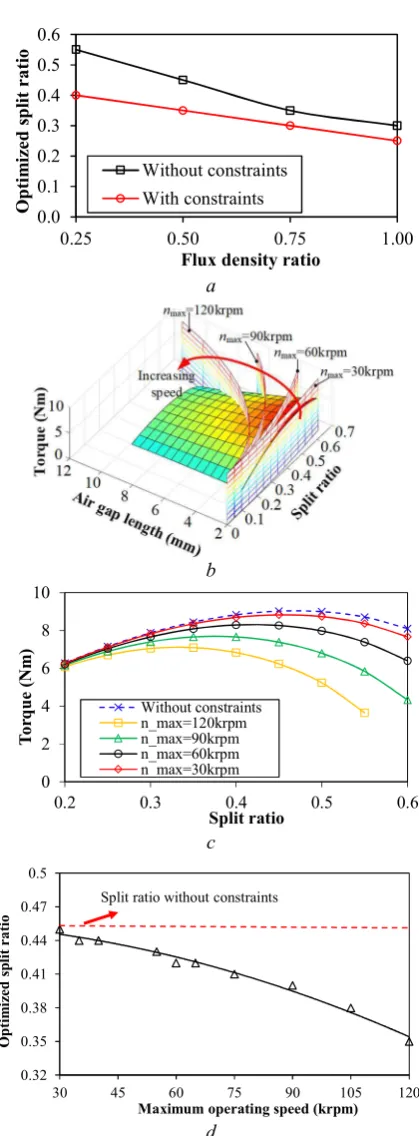
4.1. Influence of Flux Density Ratio
From (33), it can be seen that the optimized split ratio considering the mechanical constraints still depends on the slot area which is closely related with the flux density ratio. Fig. 5(a) illustrates the variation of optimized split ratio with flux density ratio, and clearly shows that the optimized value decreases with the increase of flux density ratio. This can be attributed to the increase of width of the slot teeth and thickness of yoke while the flux density ratio is increasing. Hence, the slot area is consequently reduced. In order to maintain the constant copper loss, the stator bore diameter has to be reduced. It can be seen that with the decrease of flux density ratio, the difference between the optimized split ratios with and without consideration of mechanical constraints increases. This can be attributed to the increasing air gap length with the increasing split ratio, when mechanical constraints are considered. Thus, the stator bore diameter increases faster, which in turn restricts the increase of optimized split ratio so that the copper loss can be constant.
4.2. Influence of Maximum operating speed In the practical design, the worst case should always be considered. The contact pressure between the magnet and the rotor back iron turns into the minimum when the machine operates at the maximum operating speed. Hence, the optimum split ratio is quite interdependent with the maximum operating speed at which the contact pressure must be no smaller than zero. As can be seen from (29), the mechanical constraint is closely related with the maximum operating speed. The limitation on split ratio becomes more demanding with the increase of maximum operating speed. In this section, the influence of maximum speed on the optimized split ratio for HSPMMs is investigated.
Fig. 5(b) illustrates the different surfaces with respect to the different maximum operating speeds. It can be seen that with the increase of maximum operating speed, the smaller valid surface of the designs than that without constraints can be obtained. On the other hand, as shown in Fig. 5(c), when the maximum operating speed is relatively small, the envelop of the valid designs is almost the same as that of the design surface without constraints, which means that the optimized split ratio, as well as the maximum achievable torque, remain almost stable at lower speed. Under this circumstance, the mechanical constraints can be ignored.
a
b
c
d
Fig. 5. Influence of flux density ratio and maximum operating speed on optimized split ratio (hm=8mm, carbon fibre)
(a) Variation of optimized split ratio with flux density
ratio (nmax=120kr/min)
(b) Electromagnetic torque versus split ratio and air gap length at different maximum operating speed ( =0.5)
(c)Electromagnetic torque versus split ratio at different
maximum operating speed ( =0.5)
(d)Variation of optimized split ratio with different
maximum operating speed ( =0.5) 0.0
0.1 0.2 0.3 0.4 0.5 0.6
0.25 0.50 0.75 1.00
O
pt
im
iz
ed
sp
lit
r
at
io
Flux density ratio
Without constraints With constraints
0 2 4 6 8 10
0.2 0.3 0.4 0.5 0.6
Tor
qu
e
(N
m
)
Split ratio
Without constraints n_max=120krpm n_max=90krpm n_max=60krpm n_max=30krpm
0.32 0.35 0.38 0.41 0.44 0.47 0.5
30 45 60 75 90 105 120
O
pt
im
iz
ed
sp
lit
r
at
io
Maximum operating speed (krpm)
[image:9.595.320.530.49.618.2]9 As shown in Fig. 5(d), the optimized split ratio keeps
decreasing with the increase of maximum operating speed. On the other hand, when the maximum is below 45kr/min, the optimized split ratio almost remains unchanged compared with the one without consideration of mechanical constraints. When the maximum operating speed is relatively low, the required sleeve thickness for the selected sleeve material will not be comparable to the mechanical air gap length. Thus, the air gap flux density will only drop very slightly.
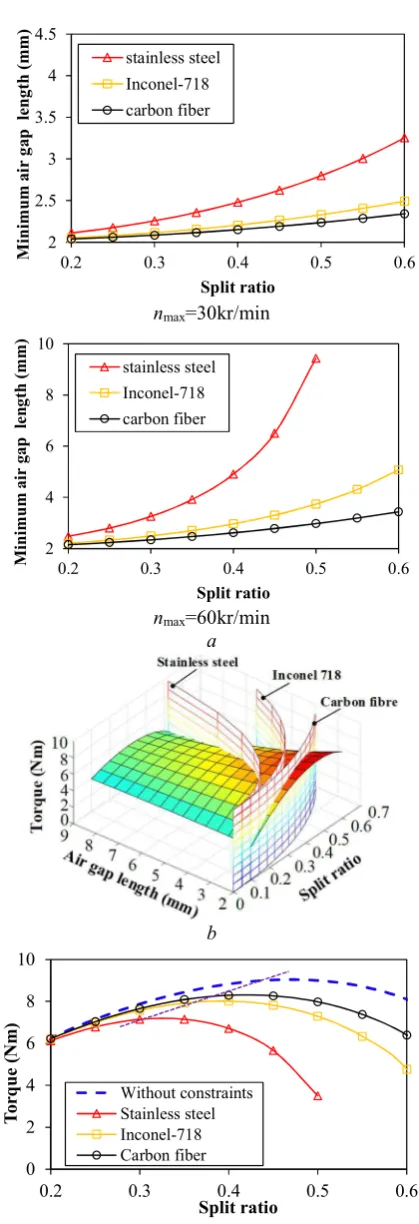
4.3. Influence of Retaining Sleeve Material
The sleeve material is very important to the design of HSPMM due to its strong tensile strength. The material properties of typical retaining sleeves and PMs are shown in Table 2. It can be seen that carbon fibre is equipped with the greatest tensile strength while the one for stainless steel has the least. However, the cost of carbon fibre is also the highest. The criteria of sleeve selection should take the cost and the electromagnetic performance as well as the mechanical robustness into consideration.
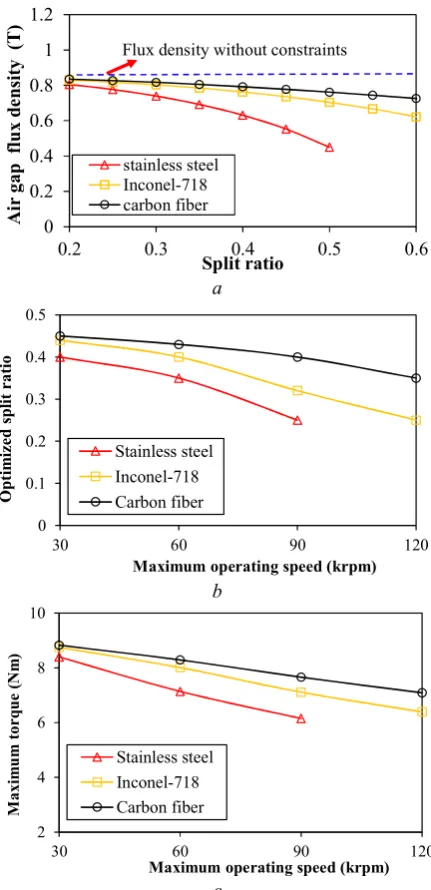
The minimum air gap length can be easily obtained from (29), as shown in Fig. 6(a). Carbon fibre shows great advantages for its smallest sleeve thickness, especially at higher speed. Fig. 6(b) illustrates the electromagnetic torque versus split ratio under the mechanical constraints with different sleeve materials at the speed of 60kr/min. It is obvious that HSPMM with carbon fibre sleeve has the highest torque density compared with the others due to the relatively larger air gap flux density. In Fig. 7(a), it can be seen that the maximum air gap flux density for the design with carbon fibre is larger than the others due to a smaller effective air gap.
As mentioned before, the maximum operating speed has a significant impact on the maximum torque as well as the optimized split ratio of HSPMM. The optimized split ratios for HSPMM equipped with three different sleeve materials, respectively, are shown in Fig. 7(b). With respect to maximum operating speed, the optimized split ratio for machines with carbon fibre is not as sensitive as the one for machines with Inconel and stainless steel.
In addition, as shown in Fig. 7(c), the maximum achievable torque for HSPMM equipped with carbon fibre is higher than that of Inconel. This difference becomes larger with the increase of the maximum operating speed which indicates that the carbon fibre is extremely suitable for ultra-high speed applications. On the other hand, the Inconel compromises the cost and mechanical robustness, exhibiting advantages in the medium speed range.
nmax=30kr/min
nmax=60kr/min a
b
[image:10.595.320.530.47.660.2]c
Fig. 6. Variation of electromagnetic torque with split ratio with respect to different sleeve material ( =0.5, hm=8mm, nmax=60kr/min)
(a) Variation of minimum air gap length versus split ratio with respect to different sleeve material (b) Electromagnetic torque versus split ratio and air gap length
(c) Output torque versus split ratio with respect to different sleeve material
2 2.5 3 3.5 4 4.5
0.2 0.3 0.4 0.5 0.6
M
in
im
um
a
ir
g
ap
l
en
gt
h
(m
m
)
Split ratio
stainless steel Inconel-718 carbon fiber
2 4 6 8 10
0.2 0.3 0.4 0.5 0.6
M
in
im
um
ai
r
gap
l
en
gt
h
(m
m
)
Split ratio
stainless steel Inconel-718 carbon fiber
0 2 4 6 8 10
0.2 0.3 0.4 0.5 0.6
To
rq
ue
(N
m
)
Split ratio Without constraints Stainless steel Inconel-718 Carbon fiber Table 2 Material properties
Material
properties (NdFeB) PM Carbon fiber Inconel 718 Steel 304 Stainless Density (kg/m3) 7400 1620 8200 7600
Young’s
Modulus (GPa) 160 140 199 196 Tensile strength
(MPa) 120 1400 1100 500
[image:10.595.52.285.70.157.2]10
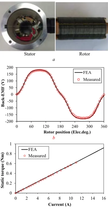
5. Prototyping and Experimental Verification
Based on the previous optimization method, a three phase, 6-slot/4-pole high speed permanent magnet machine is prototyped. As is shown in Fig. 8(a), the rotor is equipped with surface-mounted magnets which are under the protection of a carbon fibre sleeve. The prototype machine is driven by another motor to test the back-EMF waveform, Fig.8(b), in which the measured and simulated open-circuit phase back-EMFs are compared at 36krpm. The static torque is measured with the method proposed in [21] and compared with the measured result in Fig. 8(c). It can be seen that the measured results agree well with the simulated one, which further confirms the validity of analysis in this paper.
6. Conclusion
In this paper, the optimized split ratio for HSPMM has been analysed with the consideration of mechanical constraints including the sleeve circumferential stress limit and contact pressure requirement between the magnets and the rotor back iron. The analytical results have been verified by the finite element analyses and experimental data. It has been shown that the optimized split ratio is significantly reduced when the mechanical constraints are taken into account. Furthermore, the achievable torque has also been decreased sharply due to the limitation on the maximum air gap flux density. The influences of flux density ratio, as well as the sleeve material and maximum operating speed on the optimized split ratio, have also been investigated. It is shown that the optimized split ratio is reduced significantly with the increase of flux density ratio. The carbon fibre exhibits distinctive advantages among the commonly used sleeve materials with the highest torque density, making it extremely suitable for ultra-high speed applications.
a
b
[image:11.595.317.533.61.507.2]c
Fig. 7. Maximum air gap flux density and
electromagnetic torque and optimized split ratio for different sleeve material
(a) Maximum air gap flux density versus split ratio
( =0.5, hm=8mm, nmax=60kr/min)
(b) Optimized split ratio versus maximum operating
speed ( =0.5, hm =8mm)
(c) Maximum achievable torque versus maximum
operating speed ( =0.5, hm =8mm)
0 0.2 0.4 0.6 0.8 1 1.2
0.2 0.3 0.4 0.5 0.6
A
ir
g
ap
f
lu
x
de
ns
ity
(
T)
Split ratio stainless steel Inconel-718 carbon fiber
Flux density without constraints
0 0.1 0.2 0.3 0.4 0.5
30 60 90 120
O
pt
im
iz
ed
sp
lit
r
at
io
Maximum operating speed (krpm) Stainless steel
Inconel-718 Carbon fiber
2 4 6 8 10
30 60 90 120
M
axi
m
um
to
rq
ue
(N
m
)
Maximum operating speed (krpm)
11
7. References
[1] R. Ancuti, I. Boldea, and G.-D. Andreescu: 'Sensorless V/f control of high-speed surface permanent magnet synchronous motor drives with two novel stabilising loops for fast dynamics and robustness', IET Elect. Power Appl., 2010, 4, (3), pp. 149–157
[2] S. R. Gurumurthy, V. Agarwal, and A. Sharma: 'Optimal energy harvesting from a high-speed brushless DC generator-based flywheel energy storage system', IET Elect. Power Appl., 2013, 7, (9), pp. 693– 700
[3] N. Bianchi, S. Bolognani, and F. Luise: 'Potentials and limits of high-speed PM motors', IEEE Trans. Ind. App., 2004, 40, (6), pp. 1570-1578
[4] A. Borisavljevic, H. Polinder, and J. A. Ferreira: 'On the speed limits of permanent-magnet machines', IEEE Trans. Ind. Electron., 2010,
57, (1), pp. 220–227
[5] Z. Q. Zhu, K. Ng, and D. Howe: 'Design and analysis of high-speed brushless permanent magnet motors', Proc. Inst. Elect. Eng. Int. Conf.
Elect. Mach. Drives, Cambridge, U.K., Sep. 1997, pp. 358–381
[6] A. Binder and T.Schneider: 'High-speed inverter-fed AC drives', in
Proc. Int. Aegean Conf. Elect. Mach. Power Electron.,
Bodrum,Turkey, Sep. 2007, pp. 9-16
[7] J. Luomi, C. Zwyssig, A. Looser, and J. W. Kolar: 'Efficiency optimization of a 100-W 500 000-r/min permanent-magnet machine including air friction losses', IEEE Trans. Ind. Appl., 2009, 45, (4), pp. 1368–1377
[8] Z. Kolondzovski, A. Belahcen, and A. Arkkio: 'Comparative thermal analysis of different rotor types for a high-speed permanent-magnet electrical machine', IET Electr. Power Appl., 2009, 3, (4), pp. 279– 288
[9] D. Gerada, A. Mebarki, N. L. Brown, C. Gerada, A. Cavagnino, and A. Boglietti: 'High-speed electrical machines: technologies, trends, and developments', IEEE Trans. Ind. Electron., 2014, 61, (6), pp. 2946-2959
[10] A. Binder, T. Schneider, and M. Klohr: 'Fixation of buried and surface-mounted magnets in high-speed permanent-magnet synchronous machines', IEEE Trans. Ind. Appl., 2006, 42, (4),pp. 1031-1037
[11] F. B. Chaaban: 'Determination of the optimal rotor/stator diameter ratio of permanent magnet machines', Elect. Mach. Power Syst.,1994,
22, pp. 521–531
[12] Y. Pang, Z. Q. Zhu, and D. Howe: 'Analytical determination of optimal split ratio for permanent magnet brushless motors', IEE Proc. Elect. Power Appl., 2006, 153, (1), pp. 7–13
[13] L. J. Wu, Z. Q. Zhu, J. T. Chen, Z. P. Xia, and G. W. Jewell: 'Optimal split ratio in fractional-slot interior permanent-magnet machines with non-overlapping windings', IEEE Trans. Magn., 2010, 46, (5), pp. 1235–1242
[14] J. D. Ede, Z. Q. Zhu, and D. Howe: 'Optimal split ratio for high-speed permanent magnet brushless DC motors', Proc. 5th Int. Conf.
Electrical Machines and Systems, vol. 2, Aug. 2001, pp. 909–912
[15] T. Reichert, T. Nussbaumer, and J. W. Kolar: 'Split ratio optimization for high-torque PM motors considering global and local thermal limitations', IEEE Trans. Energy Convers., 2013, 28, (3), pp. 493–501 [16] A. Boglietti, A. Cavagnino, D. Staton, M. Shanel, M. Mueller, and C. Mejuto: 'Evolution and modern approaches for thermal analysis of electrical machines', IEEE Trans. Ind. Electron., 2009, 56, (3), pp. 871–88
[17] X. Fan, R. Qu, B. Zhang, J. Li and D. Li: 'Split ratio optimization of high-speed permanent magnet synchronous machines based on thermal resistance network', 2016 XXII International Conference on
Electrical Machines (ICEM), Lausanne, Sep. 2016, pp. 4-7
[18] J. Li, K. Wang, F. Li: 'Analytical prediction of optimal split ratio of consequent-pole permanent magnet machines', IET Electric Power Applications, 2018, 12, (3), pp. 365-372
[19] T. A. Lipo: 'Introduction to AC machine design', Wisconsin Power Electron. Res. Center, Univ. Wisconsin, Madison, WI, USA, 2011 [20] J. Pyrhonen, T. Jokinen, and V. Hrabovcova, Design of Rotating
Electrical Machines. Hoboken, NJ: Wiley, 2008
[21] Zhu, Z.Q.: ‘A simple method for measuring cogging torque in permanent magnet machines’. Proc. of IEEE Power Energy Society
General Meeting, 2009, pp. 1–4
Stator Rotor a
b
[image:12.595.47.275.64.504.2]c
Fig. 8. Prototype and experimental verification (a) 6-slot/4-pole HSPMM prototype
(b) Waveforms of simulated and measured phase back-EMFs (36000r/min)
(c) Measured and simulated static torque (Ia=-2Ib=-2Ic)
-200 -150 -100 -50 0 50 100 150 200
0 60 120 180 240 300 360
Bac
k-EM
F
(V
)
Rotor position (Elec.deg.)
FEA Measured
0 0.2 0.4 0.6 0.8 1
0 2 4 6 8 10 12 14 16
St
at
ic
tor
qu
e (
N
m
)
Current (A) FEA