A Living Extracorporeal Device
for Proximal Tubule Reabsorption
The Harvard community has made this
article openly available.
Please share
how
this access benefits you. Your story matters
Citable link http://nrs.harvard.edu/urn-3:HUL.InstRepos:38811519
Terms of Use This article was downloaded from Harvard University’s DASH repository, and is made available under the terms and conditions applicable to Other Posted Material, as set forth at http://
Table of Contents
1. List of Figures ... 4
2. Abstract ... 6
3. Introduction ... 7
3.1. Project Motivation...7
3.1.1 Kidney Function ... 7
3.1.2 Target Patients & Causes of Kidney Disease ... 8
3.2. Limitations of Current Treatments for Kidney Disease ...9
3.2.1. Dialysis ... 9
3.2.2. Transplantation ... 11
3.3. Identification of Problem Statement & Proposal ... 11
3.3.1. Evaluation of Problem Statement ... 11
3.3.2. Project Proposal ... 11
4. Investigation ... 12
4.1. Background Research & Prior Art ... 12
4.1.1. Proximal Tubule Reabsorption... 12
4.1.2. 3D Bioprinting of Proximal Tubules and Vasculature ... 13
4.2. Design Goals ... 15
5. Ideation ... 18
5.1. Proposed Designs ... 18
5.1.1. Fluid Adapter ... 18
5.1.2. Interfacial Component ... 19
5.2. Conclusion of Ideation Phase ... 21
6. Design Evolution ... 21
6.1. Iterative Prototyping ... 21
6.2. Material & Mechanical Testing ... 22
6.2.1. Material Characterization ... 22
6.2.1.1. HTM140 Tensile Testing ... 23
6.2.1.2. E-Shell 300 Series Tensile Testing ... 25
6.2.1.3. Conclusion of Material Characterization ... 26
6.2.2. Limitations of Material ... 26
6.2.3. Tissue Mimic ... 28
6.2.4. Pull-Out Testing ... 29
6.2.4.1. Pull-out testing results ... 31
6.2.5. Fluid Flow Testing ... 33
7. Final Prototype ... 34
8. Budget ... 35
9. Conclusion ... 36
9.1. Project Takeaways ... 36
9.2. Limitations ... 37
9.3. Future Work ... 38
9.3.3. Geometry Modifications ... 39
9.3.4. Machining Components ... 39
9.3.5. Final Assembly Testing ... 40
10. References ... 41
11. Appendix ... 43
11.1. Bill of Materials ... 43
11.2. Resin Data Sheets... 43
11.3. Back of the Envelope: Reynold’s Number ... 44
11.4. Engineering Drawings ... 44
11.5. Additional Figures ... 49
1. List of Figures
Figure 1: Close-up of kidney nephron which highlights the network of blood vessels and proximal tubules ... 8 Figure 2: Hemodialysis treatment via an external circuit (dialyzer) at a medical facility [7] ... 10 Figure 3: Dialyzer membrane transport of water and solutes [8] ... 10 Figure 4: Proximal tubule cell model of transepithelial transport [9] ... 13 Figure 5: In vivo-like phenotype of 3D bioprinted renal PTs: 3D, polarized, and
convoluted characteristics [10] ... 14 Figure 6: Fabrication of 3D bioprinted renal proximal tubule from the Lewis lab [10] .... 14 Figure 7: Printing, infilling, and fugitive ink removal steps to fabricate 3D vascular
network [11] ... 15 Figure 8: CAD design of final PT device prototype w/ a close-up of tissue chamber containing 4 channels representing PTs offset from 4 channels representing blood vessels. Direction of transport is from PT to blood vessel. ... 17 Figure 9: Luer-lock compatibility by 3D printing threading inside of the fluid adapter .... 19 Figure 10: Section views of potential modular adapter designs: (a) simple, repeatable streamlined taper design (b) side view of plenum with built-in poles design (c) top view of plenum with built-in poles design (d) parallel channel step design following Murray’s
Law ... 19 Figure 11: Passive fixation interfacial component designs: (a) barbs based off pacing lead tines (b) rings to increase surface area (c) razorblade-like design ... 20
Figure 12: Medtronic’s MRI SureScan pacing lead with 4 tines located at the tip for
passive fixation in cardiac tissue [15] ... 20 Figure 13: Dogbone testing set-up with Instron machine prior to extension ... 23
Figure 14: HTM140 dogbone dimensions & tensile testing data revealing a Young’s
Modulus of 454 MPa (n=3) ... 24 Figure 15: E-Shell dogbone dimensions & tensile testing data revealing a Young’s
modulus of 256 MPa (n=3) ... 25 Figure 16: Summary of results from testing the limitations of nozzle printing with
Figure 22: Fluid flow testing taking place at 40mL/min. Therefore, all 4 nozzle outlets
are releasing 10mL/min at uniform flow. ... 34
Figure 23: Final PT device prototype. (a) PDMS gasket used as foundation (b) Tubule cross-section close-up (c) Adapters w/ metal pins prior to assembly (d) Top-view of final prototype with metal pins engrained ... 35
Figure 24: CAD design of final prototype with close-up of tissue chamber where reabsorption of nutrients occurs across the tubules and within the tissue mimic. ... 35
Figure 25: Examples of printing errors include air bubbles, microscopic holes, uneven hole diameters, and altered nozzle geometry around barbs. ... 38
Figure 26: Original lap shear testing set-up. Must be adapted in future work to make more rigid and less fragile. ... 39
Figure 27: Engineering drawing of razorblade interfacial design ... 44
Figure 28: Engineering drawing of single nozzle w/ rings ... 45
Figure 29: Engineering drawing for single straight nozzle ... 45
Figure 30: Engineering drawing for single nozzle w/ 45º barbs ... 46
Figure 31: Engineering drawing of single nozzle w/ -45º barbs ... 46
Figure 32: Engineering drawing for plenum fluid adapter w/ poles built-in ... 47
Figure 33: Engineering drawing of simple, streamlined taper fluid adapter design ... 47
Figure 34: Engineering drawing of parallel channel step design based on Murray's law ... 48
Figure 35: Engineering drawing for barb array used to test limitations of printer ... 48
Figure 36: Engineering drawing of nozzle array used to test limitations of printer ... 49
Figure 37: Top nozzle-tip view of streamlined taper design ... 49
Figure 38: Side profile of final 3D printed fluid adapter... 50
Figure 39: Close-up of embedded luer-lock threading... 50
Figure 40: Polished section view of 3D printed plenum adapter w/ built-in poles ... 51
Figure 41: Raw data of -45º barbed HTM140 single nozzle pull-out testing ... 51
Figure 42: Raw data of straight HTM140 single nozzle pull-out testing ... 52
Figure 43: Raw data of 45º barbed HTM140 single nozzle pull-out testing ... 52
Figure 44: Raw data of -45º barbed E-Shell single nozzle pull-out testing ... 53
Figure 45: Raw data of straight E-shell single nozzle pull-out testing ... 53
2. Abstract
Currently, 700,000 patients suffer from end-stage renal disease (ESRD) with treatment costs over $42B in the US, yet the 5-year survival of patients on dialysis is only 35% while that of full-organ transplantation is over 80%. Despite these
3. Introduction
Over the past six months, Matthew Hink has designed and proposed a project to advance towards the goal of organ regeneration for Jennifer Lewis’ Lab at the Wyss Institute for Biologically Inspired Engineering. This project includes beginning steps towards a living extracorporeal device for proximal tubule reabsorption which is utilized in conjunction with 3D bioprinted proximal tubules from the Lewis Lab.
3.1. Project Motivation
Twenty-two people die per day waiting on an organ transplant [1]. At the rate of nearly one death per hour, organ supply is an ever-increasing concern as the waiting list continues to grow over time. Every 10 minutes another person is added to the list, and as of September 2016, kidney demand makes up approximately 80% of this 120,000-person waiting list [1]. These 100,000 kidney transplant candidates equate to the
demand, yet in 2016, only ~20,000 kidney transplants were performed [1]. The need for donor kidneys is rising at about 8% per year. However, despite efforts to increase enrollment, the number of donors remains constant, driving the need for innovative solutions to the organ shortage crisis. The lives behind these unsettling statistics are the driving force for kidney organ engineering and motivation for this project, which explores the possibilities of mechanically interfacing tissue engineered proximal tubules with one of these 100,000 at-risk patients.
3.1.1 Kidney Function
The kidney is an essential organ of the human body. Blood vessels and proximal tubules make up a network in the organ which consists of about 1 million nephrons as shown in figure 1. These nephrons perform two key functions, filtration and
reabsorption. As blood enters the nephron, filtration occurs as blood cells and other large molecules, including proteins, are prevented from passing through. The process is driven primarily by hydraulic pressure (blood pressure) in the capillaries of the
Figure 1: Close-up of kidney nephron which highlights the network of blood vessels and proximal tubules
3.1.2 Target Patients & Causes of Kidney Disease
A kidney disease is diagnosed when the organ is no longer filtering blood normally or if damage has occurred to the organ. Chronic kidney disease appears in several stages outlined below with the most severe being End-Stage Renal Disease (ESRD). Stages are typically based off the glomerular filtration rate (GFR), the rate at which the kidneys filter wastes and extra fluids from blood.
Five Stages of Chronic Kidney Disease [3] 1. Normal kidney function (GFR ≥ 90 mL/min) 2. Mild loss of kidney function (GFR 60-89 mL/min)
3. Mild to severe loss of kidney function (GFR 30-59 mL/min) 4. Severe loss of kidney function (GFR 15-29 mL/min)
5. ESRD: Kidney failure requiring dialysis or transplant for survival (GFR ≤ 15 mL/min)
There are many causes of kidney disease, yet diabetes and high blood pressure are two of the main players. Diabetes can damage the glomeruli, or filters of the
kidneys, and lead to an abnormal amount of protein (albumin) leaking into the urine. This is because the increase in blood sugar can cause a rise in some chemicals within the kidney that make the glomeruli leakier. High blood pressure can lead to kidney failure because arteries around the kidney will narrow, harden, or weaken and as a
result, not enough blood will reach the kidney tissue. The nephrons will no longer be able to filter blood because they will not receive enough oxygen and nutrients. One danger of this disease is that in its early stages, few to no symptoms are shown and therefore it can go undiagnosed until later stages. When nearing ESRD, a person would notice symptoms caused by a buildup of waste and extra fluid in their body. While incident rates for ESRD have slightly declined since 2006, the ESRD prevalent cases continue to rise at about 21,000 cases per year with the number approaching 700,000 U.S. citizens in 2015 [3].
3.2. Limitations of Current Treatments for Kidney Disease
Current treatment options for ESRD are limited. When a patient’s kidney function falls below 10%, dialysis treatment is required. Over time, as the patient’s condition worsens, a kidney transplant is required for long-term survival. While ESRD is not curable, these two treatments do offer a way to extend patient life, however, both suffer from severe limitations.
3.2.1. Dialysis
Dialysis is responsible for filtering and cleaning blood when your kidneys can no longer perform these functions. Hemodialysis is the most common type and treats by performing non-continuous kidney function to an individual typically three times per week through an external filtration circuit (dialyzer) at a medical facility as seen in figure 2. Each of these three sessions typically last 3-5 hours which is an inconvenience and life-changing feature of this treatment option. The dialyzer has one compartment for blood and one for dialysate separated by a thin membrane (figure 3). Blood cells and proteins stay in your blood as they are too large to cross the membrane but smaller waste products travel through the membrane and are washed away. This filtration process is a traumatic experience for the individual’s body given that days’ worth of filtering is done in just a few hours.
asked to increase protein intake while limiting the amount of potassium, phosphorus, sodium and fluids in their diet [4]. The five-year survival rate of patients on dialysis is about 35% [5], and today, 468,000 ESRD patients are on dialysis [6]. The dialysis industry comes with several shortcomings so alternatives must be found since ESRD patients are growing in number and donors not near as quickly.
Figure 2: Hemodialysis treatment via an external circuit (dialyzer) at a medical facility [7]
3.2.2. Transplantation
The ideal treatment for ESRD is an organ transplant. The five-year survival rate for individuals with a kidney transplant is over 80% [5]. If every ESRD patient could receive a kidney transplant they would, but when there are 100,000 individuals on the waiting list and just under 20,000 donor kidneys available per year, this cannot be the case. Today, 193,000 ESRD patients have a functioning kidney transplant [6], whether coming from both living or deceased donated kidneys. The limitations of this treatment are a lifetime of immunosuppressant medications to prevent your body from rejecting the organ as well as chronic immune rejection over time. Organ transplants last 10-15 years before an individual needs a replacement transplant. Rejection can lead to infections and cancers, yet the treatment remains ideal because of the continuous kidney function that it provides when successful.
3.3. Identification of Problem Statement & Proposal
3.3.1. Evaluation of Problem Statement
Limitations of current treatments show us that there is not only a gap in supply and demand of kidney organs, but also that dialysis lacks full kidney functionality. One of the main functions of the kidney is nutrient and fluid reabsorption and dialysis does not provide this function. Therefore, the problem this project aims to address is the lack of the kidney reabsorption function that exists in dialysis by providing initial building blocks of a device that could be used in conjunction with dialysis to begin and later be scaled up to a full organ years down the road.
3.3.2. Project Proposal
The Lewis Lab and I, under the direction of David Kolesky, agreed to work together to address this mismatch and on a larger scale, provide an alternative to other existing treatments such as hemodialysis and transplantation. The ideal solution to this problem would be a fully functioning artificial organ that filters blood, reabsorbs nutrients,
technology being developed in the Lewis Lab; we have taken steps towards
mechanically interfacing 3D bioprinted kidney tissues to individuals with ESRD. Our goal is to replace intermittent dialysis with a more biomimetic tissue-based platform that can serve as a bridge-to-transplantation or a suitable alternative to organ
transplantation. In this work, we aim to design and optimize a milli- and microfluidic manifold geometry, to maximize the interfacial strength of the tissue-adapter interface and, ultimately, to enable perfusion of 3D tissues at high flow rates (100s of mL/min) that occur during hemodialysis.
4. Investigation
The investigative phase of this project consisted of a deep dive into literature and previous work done by the Lewis Lab in the 3D bioprinting space. Because there were no existing methods or products that performed the same function we wanted this device to, most the design parameters and specifications had to be created based on similar processes or intuition developed through literature review.
4.1. Background Research & Prior Art
4.1.1. Proximal Tubule Reabsorption
Figure 4: Proximal tubule cell model of transepithelial transport [9]
4.1.2. 3D Bioprinting of Proximal Tubules and Vasculature
The Lewis Lab specializes in 3D bioprinting, among other things, and has been taking steps towards achieving organ regeneration. In the past few years, they have created methods to produce in vitro 3D renal proximal tubules (figures 5,6) and
vascularized tissue constructs (figure 7). They combined bioprinting, 3D cell culture, and organ-on-a-chip concepts to accomplish this. In creating a 3D bioprinted model for drug screening, their goal is to transform this model into a therapeutic tissue. The tubules are housed in perfusable chips and are embedded in an extracellular matrix, with abilities to be maintained for over two months [10]. The proximal tubules are open lumens that are lined with proximal tubule epithelial cells (PTECs) that exhibit similar functions to the in vivo counterparts highlighted by their 3D, polarized, and convoluted characteristics. A silicone gasket is printed as the outer border and then filled with an extracellular matrix (ECM) made of gelatin-fibrin hydrogel. From there, a “fugitive ink” is printed onto the ECM, connected to hollow metal pins and then another layer of ECM is printed on top. This chip is cooled so the fugitive ink liquefies and then is evacuated to leave behind an open channel. This open channel is perfused with cell media using an external
increased to have any therapeutic use as there are 20,000 of these single channels that exist in the kidneys.
Figure 5: In vivo-like phenotype of 3D bioprinted renal PTs: 3D, polarized, and convoluted characteristics [10]
Figure 7: Printing, infilling, and fugitive ink removal steps to fabricate 3D vascular network [11]
4.2. Design Goals
Despite recent advances in 3D bioprinting of functional kidney tissue, scaling tissue-based therapies towards therapeutic use has proven to be an obstacle due to mechanical and design-related challenges associated with interfacing soft tissues with rigid fluidic components at high flow rates. The long-term aim of this project is to design and build a biomimetic tissue-based platform that can serve as a bridge to
Design Specifications
• Modular Adapter
o 4-8 tubules
o Inlet: ¼” diameter
o Outlet: 300 µm diameter
• Perfusion flow rates
o Native proximal tubule scale: 1𝛍𝐋/𝐦𝐢𝐧
o Dialysis scale: 100s of mL/min
• Uniformly distribute fluid
• Maximize interfacial strength between tissue-adapter interface
• No coagulation
• Minimize pressure drop
The first specification addresses the feature that the fluid inlets must be able to interface with both the tissue platform and potentially a dialysis machine. Therefore, on one end it must be compatible with commercial dialysis-scale tubes and on the other end it must be able to perfuse through the lab scale tubules around 300 µm in diameter. For the scope of this project, we started on a small scale and aimed to create
components to fit with 4-8 proximal tubules compared to the 20,000 of them that exist in the kidney. This is because the Lewis lab has not yet scaled up their soft tissue and therefore it was unnecessary for us to jump to such a large scale for the project.
This project needed to meet an upper and lower bound in perfusion flow rates to meet specification. The lower bound is the perfusion rate that occurs in a native
proximal tubule and in the Lewis lab, while the upper bound was dialysis flow rates because of the need to potentially work in conjunction with that process. This means that the adapters must take in these flow rates through the inlet, but then the flow will be split among multiple nozzles and therefore the flow rate through the nozzles into the tubules will not be the same as upon entrance to the adapter. The continuity equation tells us that in a control volume, all flow that goes in must come out, and therefore, if 300 mL/min goes in one inlet, then 75 mL/min (300mL/min/4) will be ejected from each of the 4 outlets and perfused through the tubules. Fluid adapters need to supply uniform fluid distribution so that the tissue can behave symmetrically in the platform and perform reabsorption equally across the tubules.
tissue-adapter interface. Currently, interfacing stiff materials (needles, 3D prints, etc.) with the soft tissue mimic (~1 kPa) has proven to be a challenge for the group. Often there is leaking that occurs around the needle-hydrogel interface and then fluid travels into the neighboring tissue.
Two specifications that were not measured in this project are preventing
coagulation and minimizing the pressure drop across the adapter. Coagulation, or blood clotting, occurs when blood transforms from a liquid into a gel. Turbulent flow or vortices in flow can lead to coagulation and therefore we want to avoid these flow
characteristics. Moving forward, this entire tissue platform would be created with non-thrombogenic surfaces to prevent the need for patients to use anticoagulants as they do in dialysis. The use of anticoagulants comes with risks of excessive blood lose because they increase the time it takes for blood clots to form. Due to the geometry of the
[image:17.612.195.428.408.676.2]adapter, an increase in pressure is bound to occur from inlet to outlet because of the difference in diameter. However, this ideally would be minimized to avoid having an immensely high pressure system, and therefore the geometry would be optimized to result in the smallest pressure drop across the platform.
Figure 8: CAD design of final PT device prototype w/ a close-up of tissue chamber containing 4 channels representing PTs offset from 4 channels representing blood vessels. Direction of
5. Ideation
5.1. Proposed Designs
5.1.1. Fluid Adapter
The modular fluid adapter was one of the essential components of the project given the goals of uniform fluid distribution, no coagulation, and a minimized pressure drop. Additionally, this component is required to meet design specifications mentioned previously including a ¼” diameter inlet and 4-8 300 µm outlets while being able to withstand flow rates up to 100s of mL/min. Because it is a modular adapter, we want it to be able to interface with a variety of inlet tubing and therefore all the adapter designs are luer-lock compatible as shown in figure 8. Early in the ideation process, several designs were considered after literature review on fluid flow, microfluidics and discussions with the Weitz Lab at Harvard University. Our initial intuition was to stay simple with the design and as streamlined as possible to avoid potential turbulent flow or stagnation in flow. With that in mind, I designed an adapter that tapers directly from a ¼” inlet to the 4 300 µm outlets. Drawing from literature, another design considered for the adapter was a plenum chamber with built-in poles. This geometry follows a mesh or network design [12] scaled up from microfluidics to help break up initial pressure that enters the chamber from the inlet. Theoretically, this design would help avoid stagnation but could potentially lead to turbulence in flow or vortices to form in the chamber. A final design that was researched was a parallel channel step design that followed Murray’s Law. The law is a relationship that holds true when looking at the radii of parent
Figure 9: Luer-lock compatibility by 3D printing threading inside of the fluid adapter
Figure 10: Section views of potential modular adapter designs: (a) simple, repeatable streamlined taper design (b) side view of plenum with built-in poles design (c) top view of plenum with built-in
poles design (d) parallel channel step design following Murray’s Law
5.1.2. Interfacial Component
The interfacial component of the adapter was the other essential piece of the project given the design goal of maximizing interfacial strength and the current
challenges described in the Lewis Lab regarding the stiff material-soft tissue interface. 6.35 mm
a b c d
Because the fluid adapters interface with an artificial tissue platform rather than an actual patient’s tissue or vein, design decisions and testing are performed to mimic that. In approaching design, there were no quantitative metrics that drove our ideation from the beginning because we were not aware of the pressures and loads that these mechanical aspects would undergo during perfusion. However, we did know that
difficulties were arising with straight needles interfacing with the tissue mimic in previous work, and therefore, we aimed to integrate mechanical aspects onto the adapters to better grab the hydrogel. Literature review of active and passive fixation techniques was performed, but for this project, we looked specifically at designs for passive fixation. Different passive fixation features were designed by varying the geometry. A few of the designs we sought out are depicted below. We chose to focus on and thoroughly test the barbed design for this project scope because of products that exist in the medical device market today such as pacing leads that use tines or barbs as passive fixation techniques to grab onto cardiac tissue [14] (figure 11).
Figure 11: Passive fixation interfacial component designs: (a) barbs based off pacing lead tines (b) rings to increase surface area (c) razorblade-like design
Figure 12: Medtronic’s MRI SureScan pacing lead with 4 tines located at the tip for passive fixation in cardiac tissue [15]
b c
5.2.
Conclusion of Ideation Phase
For the scope of this project, the streamlined, tapered fluid adapter was pursued for extensive prototyping and testing because of its simple design and ability to be rapidly prototyped to a degree of precision that was necessary. The other, more complex designs did not have as great of precision via rapid prototyping with the 3D printer. If allotted more time and resources it would be ideal to prototype and test the other adapter designs and potentially optimize their geometries, and/or to innovate new designs that would meet the specifications outlined in 4.2. Regarding the interfacial component, the barb design was pursued for this project because of the current geometries used in medical devices such as pacing leads that passively fixate to cardiac tissue. Again, with additional time it would be ideal to thoroughly explore the other various interfacial designs to conclude which designs ultimately maximize the interfacial strength between the fluid adapter and the soft tissue mimic.
6. Design Evolution
6.1.
Iterative Prototyping
An immense aspect of this project was the iterative cycle between designing, prototyping, measuring, and analyzing the various components of this device.
isopropyl alcohol (IPA) to remove excess resin and put in a UV cure box for thirty seconds apiece to cure pieces quicker. Then, components would be examined under a Keyence microscope to take images, look for any defects, and confirm the print was done correctly off the design. From there the cycle turned to measuring and analyzing the piece using one of the specified testing methods. Based on those results, the design was modified and process repeated. This process of iterative prototyping worked to test the limits and capabilities of the Aureus 3D printer.
6.2.
Material & Mechanical Testing
A variety of material and mechanical testing was performed to characterize the materials we would be using as well as measure and analyze several variables in this project associated with interfacial strength and fluid flow. Material testing was done to find properties of the materials but also to test the limitations of the materials when prototyped with the 3D printer. For interfacial strength mechanical testing, we focused on three main variables including material (HTM140 vs. E-Shell), surface area (straight nozzles vs. textured nozzles), and geometry (45º barbs vs. -45º barbs). This testing will be explained in detail in 6.2.4., but we were able to test two different forms of each variable to see how those factors affected the interfacial strength and how they played into beam deflection with the interfacial component (barbs). A lower beam deflection would theoretically result in a higher interfacial strength as the barbs would not give as much to the hydrogel and instead stay embedded. The barbs could be defined as beams protruding from the adapter nozzles with a uniform load being applied by the hydrogel. Deflection for a cantilever beam with a uniform load applied is calculated using:
𝑦 =𝑊𝑙
3
8𝐸𝐼
W = Load, l = Length, E = Young’s Modulus, I = Moment of Inertia
6.2.1. Material Characterization
the material used in future work, but it could not be rapidly prototyped for this project. Two materials were used in this project, one being HTM140 (green, opaque ceramic filler) resin and the other being E-Shell 300 Series (transparent) resin. Both materials offered advantages of their own, but ultimately the strongest material is what this project would use for its final prototype as it could be rapidly prototyped and still maintain
strength. Identical strength testing was done for these two materials which allowed selection of final material.
6.2.1.1. HTM140 Tensile Testing
The green resin is produced by EnvisionTEC and is a high temperature mold material. The material has a heat deflection temperature of 140ºC immediately when removed from the machine after printing [16]. Some applications for this resin are consumer goods, manufacturing, and entertainment. This resin can meet a high
[image:23.612.188.421.429.665.2]resolution as it can be printed in 25 µm layers using visible light. The resin is an opaque ceramic filler that appears green. To test the strength of the material and acquire the Young’s Modulus, a dogbone was printed according to ASTM standards and tensile tested in an Instron Machine as shown in figure 7. Testing was performed using a 5kN load cell at 5mm/min.
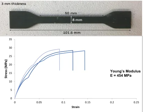
The full dogbone is 101.6 mm in length with the middle straight segment
measuring 50 mm. The cross-sectional area of the middle segment is 24 mm2 (8 mm x 3 mm). In testing, the force or load and the extension were collected to calculate the shear and strain with the geometric quantities. Shear and strain were calculated as follows.
Shear (MPa) = σ = Force (N) Area (mm2)
Strain = ε = Change in Length (mm) Initial Length (mm)
[image:24.612.73.542.323.691.2]Once shear and strain were plotted against one another, the Young’s modulus was calculated by taking the slope of the curve before yielding occurred. This quantity would be in MPa since strain is dimensionless.
Figure 14: HTM140 dogbone dimensions & tensile testing data revealing a Young’s Modulus of 454 MPa (n=3)
0 5 10 15 20 25 30 35
0 0.05 0.1 0.15 0.2 0.25
Str
ess
(M
P
a)
Strain
6.2.1.2. E-Shell 300 Series Tensile Testing
[image:25.612.72.543.262.648.2]The clear resin is produced by EnvisionTEC and is known for its rigidity and durableness. The material is a photo-reactive acrylate that can only be used on printers that provide UV light [17]. Some applications for this resin are hearing aids and other medical devices. This resin is not able to meet as high of a resolution as the green resin as it can only be printed in 100 µm layers using the UV light. The resin is transparent and appears clear when printed and turns slightly opaquer once rinsed with isopropanol. Instron testing, data collection, and the geometry of the dogbone were identical for E-Shell as they were for the HTM140 resin.
Figure 15: E-Shell dogbone dimensions & tensile testing data revealing a Young’s modulus of 256 MPa (n=3)
0 5 10 15 20 25 30 35
0 0.05 0.1 0.15 0.2 0.25
Str
ess
(M
P
a)
Strain
6.2.1.3. Conclusion of Material Characterization
Tensile testing of the two resins displayed that the green resin has a higher Young’s Modulus than the clear by almost two times, and therefore is a stiffer material. Consequently, the results show that the clear resin is more flexible and ductile and can reach a higher strain. This supports physical intuition when examining these pieces as the clear resin had significantly more flex in it than the green resin which feels more brittle. This also was portrayed in some of the barbs and visualizing how much the clear ones could deflect compared to the green ones without breaking. These results allowed us to select the green resin as our final prototype material due to its stiffness and
resolution, while we would use the clear resin to scale up fluid adapters for flow visualization purposes.
6.2.2. Limitations of Material
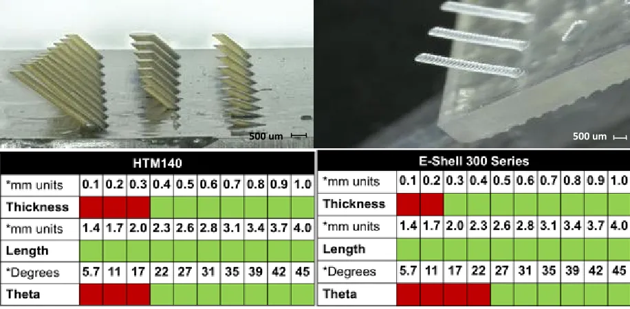
After observing some micro-scale inconsistencies (holes not being printed all the way through) between CAD designs and resulting prints from the Aureus, we aimed to test the limits of the 3D printer with both resins to see what precision and resolution we could reach with our features. In doing so, arrays of nozzles and barbs were designed, printed, and imaged to conclude what scale could be reached and help drive designs moving forward.
Figure 16: Summary of results from testing the limitations of nozzle printing with HTM140 and E-Shell on the Aureus 3D printer
To test what barb sizes were printable, an array was designed that varied barb thickness, barb length, and the angle of barb from the flat surface. Barb thickness was tested in 100µm increments from 100µm to 1000µm (1mm). Barb length was tested in 300µm increments from 1.4mm to 4.0mm. Barb angle was tested in unequal increments from 5.7º to 45º. A success meant that a barb protruded from the surface without
breaking and made the correct angle with the surface. The results displayed that the 3D printer and material could produce barbs of thicknesses greater than 300µm, angles between 21.8º and 45º to a surface, and lengths of inconclusive length (all lengths printed successfully).
500 um
500 um
Figure 17: Summary of results from testing the limitations of barb printing with HTM140 and E-Shell on the Aureus 3D printer l
6.2.3. Tissue Mimic
To mimic human tissue, the Lewis Lab uses a processable, perfusable
extracellular matrix made of Gelatin-fibrin hydrogel as was already stated in 4.1.2. Main components include gelatin for its printability and thermal response and
transglutaminase (Tg) for its mild cross-linking and long-term stability. In the group’s original work, fibrinogen (precursor to fibrin) is included for its rapid gelation, fibrillary architecture, and enhanced cell-adhesion. In this project, we aim to address purely mechanical aspects of the fluid interface device, so we decided to exclude fibrinogen to reduce costs. The gelatin was used as a tissue mimic in our pullout testing to see how the stiff nozzles interacted with the soft hydrogel. Hydrogels consist of a high water content and permeability for oxygen, nutrients, and other water–soluble metabolites making than an attractive biomaterial for tissue scaffolds [18]. Therefore, these innate properties of a hydrogel make it ideal for transport from the proximal tubules to the vasculature.
Gel preparation protocol:
In all samples, our gel formulation was 5 w/v% gelatin and 0.2% Tg. To create this gelatin-based tissue mimic, we first prepare a variety of biomaterial solutions.
We dissolve Tg powder in Dulbecco’s phosphate-buffered saline (DPBS w/ Ca2+) at 6 w/v%. The Tg solution was mixed and placed on heat (37ºC) for 20-30 minutes and sterile filtered prior to use. Porcine gelatin (Type-A, High Bloom) is dissolved in DPBS at 70ºC for 12 hours. This solution is sterile filtered and stored in a 4ºC refrigerator. Then the solutions are diluted at appropriate concentrations with Antibiotic-Antimycotic (AA) and additional DPBS. This solution was slowly mixed using a pipette and then placed on heat (37ºC) for 20-30 minutes. This final Gelatin solution then is cast in the desired volume and covered/refrigerated overnight to allow crosslinking of the gel.
6.2.4.
Pull-Out Testing
A bulk of the mechanical, interfacial testing occurred by way of pull-out tests. The goal with this testing was to measure the force and energy required to pull nozzles of varying geometry out of the tissue mimic. These tests were performed using 3D printed nozzles, gelatin tissue mimic, and an instron machine. Testing was done using three different geometries for each of the two materials. Nozzles were printed straight with no barbs, 45º barbs, and -45º barbs (figure 18). Upon initial testing, a 3x3 array of nozzles were printed and embedded in a petri dish of gelatin. Instron testing involved a tensile test extending at 5mm/min, pulling the nozzles out of the gel. Observing the physical results, it was evident that there was a reinforcing effect occurring amongst the array as the nozzles were pulling away chunks of gelatin rather than just releasing themselves. Therefore, the test was examining the gel-gel interface rather than the nozzle-gel interface since the arrays were still embedded in gelatin as shown in figure 19b.
Thus, the design was modified to single nozzles so that we could examine only the nozzle-gel interface. The single nozzles were tested the same way by embedding them in gelatin in a petri dish and running a tensile test on a 10N load cell at 5mm/min extension rate (figure 20). 8 nozzles were tested per geometry per material.
equates to a smaller beam deflection. The expectation for the various geometries from highest peak load and energy to lowest was 45º barbs > straight > -45º barbs. 45º barbs should be higher than straight nozzles because the surface area interacting with the gelatin increases, and the the anisotropic nature of the barbs has them acting against the load. The straight nozzles should be higher than the -45º barbs because based on porqupine quill theory [19], the -45º barbs would be penetrating the gelatin and
[image:30.612.167.431.215.485.2]essentially cutting it as the load was applied.
Figure 18: Varying geometries of nozzles for E-Shell (top) and HTM140 (bottom). From left to right: 45º barbs on nozzle, straight nozzle w/ no barbs, -45º barbs on nozzle
1 mm
Figure 19: Pull-out testing w/ 3x3 nozzle arrays. a) 3x3 array of -45º barbed nozzles b) 3x3 array of straight nozzles that held on to gel after testing c) Instron testing set-up for 3x3 nozzle arrays d)
3x3 arrays of each geometry embedded in gelatin in petri dishes prior to testing
Figure 20: Single straight nozzle during pull-out testing
6.2.4.1. Pull-out testing results
Our results generally presented trends and confirmed our hypotheses. Analyzation of the data included averaging the load v. extension quantities for all 3 geometries per each material. That data is presented in figure 21a,b. Additionally, the area under the curve (energy) was calculated and peak loads of all 8 specimens per geometry per material were averaged as presented in figure 21c,d. Raw data of the pull-out testing can be found in the Appendix.
Results showed that peak loads and required energy were greater for HTM140 compared to E-Shell for all geometries which supported our hypothesis. Specifically looking at HTM140, our results show that there was a 14% increase in peak load from
-1 mm 1 mm
6.35 mm
a) b)
d)
45º to straight and a 12% increase from straight to 45º. For required energy, there was a 54% increase from -45º to straight. Required energy from straight to 45º did not support our hypothesis and therefore we would expect that due to sample size or outliers, the straight energy should be less or the 45º energy should be greater. For E-Shell, the trend from straight to 45º supported our hypothesis as the peak load
increased by 39% and the required energy increased by 70%. However, the same trend was not present for -45º to straight thereby showing that straight peak loads and energy should be greater and/or -45º peak loads and required energy should be lower.
Overall, positive trends were shown that supported our hypotheses. The results show that the standard deviations are rather large which leads me to believe that additional testing or increasing the sample size would lower the standard deviation as outliers would be diminished and more of a conclusive trend would surface. Additionally, the peak loads we found were small as they were all under 0.25N. This could be a result of the tissue mimic not containing fibrinogen which would bring more of a fiber network for the barbs to grab onto, or a result of this test being a single nozzle rather than
Figure 21: Pull-out testing results (H = HTM140, E = E-Shell, error bars represent std. dev.): (a) Averaged Load v. Extension data for HTM140 (n=8) (b)Averaged Load v. Extension data for E-Shell
(n=8) (c) Required energy to pull out nozzles from gelatin (d) Peak loads of nozzle-gel interface before nozzle displaces from gel
6.2.5.
Fluid Flow Testing
Fluid flow testing was performed with the goal of visualizing uniform fluid
distribution through the adapter nozzles and meeting or design specification. Originally this project set out to test the nozzles with a dialysis machine at 100s of mL/min that is accessible in Longwood Medical Center, however, we were not able to accomplish this in the timeline of project. Instead, flow testing was performed using a Harvard
Apparatus syringe pump which can reach maximum flow rates of 40 mL/min. So, while the adapter was receiving 40mL/min through its inlet, it was releasing 10mL/min from each of the 4 nozzles. While this is less than half of the magnitude that we set out to
0 0.03 0.06 0.09 0.12 0.15 0.18
0 2 4 6 8 10 12 14
Lo ad ( N) Extension (mm) 45 Straight Negative 45 0 0.03 0.06 0.09 0.12 0.15 0.18
0 2 4 6 8 10 12 14
Lo ad (N ) Extension (mm) 45 Straight Negative 45 0 0.2 0.4 0.6 0.8 1 En ergy (mJ ) H H
H E E E
0 0.05 0.1 0.15 0.2 0.25 Peak Lo ad (N)
H E H E H E
45º Straight -45º 45º Straight -45º
HTM140 E-Shell
a) b)
test, it was promising to see the adapters handle 40mL/min well with uniform fluid distribution and no leaking.
Figure 22: Fluid flow testing taking place at 40mL/min. Therefore, all 4 nozzle outlets are releasing 10mL/min at uniform flow.
7. Final Prototype
The final prototype for this project is a foundation for what a kidney tissue platform could look like moving forward with this research. The final assembly is not as robust as initially intended because this project became a deeper dive into the device’s
components rather than its final assembly. For this prototype, a 1”x1” SE 1700 PDMS gasket is printed onto a glass slide as a foundation. Then, four more square PDMS pieces of the same size are printed to use as layers on the foundation. The fluid
adapters are sandwiched and compressed between these PDMS layers with one layer of PDMS offsetting the two sets of channels. The middle chamber is then filled with gelatin and sealed by a top acrylic piece that applies compression to the PDMS layers and fluid adapters. Once the gelatin is cross-linked overnight, the channels are
Figure 23: Final PT device prototype. (a) PDMS gasket used as foundation (b) Tubule cross-section close-up (c) Adapters w/ metal pins prior to assembly (d) Top-view of final prototype with
metal pins engrained
Figure 24: CAD design of final prototype with close-up of tissue chamber where reabsorption of nutrients occurs across the tubules and within the tissue mimic.
8. Budget
Budget was not a key factor in this project as a substantial amount of the material and services were sponsored by the Lewis lab and I was able to stay <$100 through the Active Learning Labs. A couple of areas cost came into play were with the 3D printing and tissue mimic. For printing purposes, the resin materials from EnvisionTEC are expensive so while using the 25 µm layer height for every printed piece would have given the best resolution, it would have also used a lot more resin which is why most prints were done at 50 µm layer heights. Additionally, the ECM matrix used by the Lewis
6.35 mm
25.4 mm
6.35 mm
6.35 mm
Lab in the proximal tubule chips contains fibrinogen which is a costly component, and therefore, for this project we omitted the fibrinogen as it was unnecessary and costly.
9. Conclusion
9.1. Project Takeaways
This project has been able to lay a foundation and take initial steps towards interfacing the kidney tissue technology being developed in the Lewis Lab with a potential ESRD patient. The modular fluid adapters and the interfacial component are the two essential features of this potential PT device. Various designs, prototyping methods, and testing methods were created and/or used in this project to observe trends and provide work to build on. This project produced modular fluid adapters that were of the scale required by the design specifications and that uniformly distributed fluid. The project did not reach its final assembly dialysis scale flow rates due to a shortage of time, but it was able to do some preliminary fluid flow testing through the adapters. Lastly, this project displayed how increasing surface area and optimizing geometry of passive fixation features result in a positive trend of increasing interfacial strength between the stiff nozzles and soft tissue mimic. These preliminary findings open ample opportunities for future work.
Design Specifications
• Modular Adapter o 4-8 tubules
o Inlet: ¼” diameter
o Outlet: 300 µm diameter
• Perfusion flow rates
o Native proximal tubule scale: 1𝛍𝐋/𝐦𝐢𝐧
o Dialysis scale: 100s of mL/min
• Uniformly distribute fluid
• Maximize interfacial strength between tissue-adapter interface
• No coagulation
9.2. Limitations
This project’s key limitations involved the Aureus 3D printer and the printing materials. One key limitation was the inability of the Aureus 3D printer to repeatedly print accurate parts of identical design and have it align with the CAD file dimensions. Due to resolution conflicts, designs were modified so that pieces could be printed successfully. However, even if the printer had the capability to print to a necessary resolution, not every print would turn out successful or the same as the others of identical design. This presented the greatest challenge when designing the fluid
adapters as prints would come out with micro-sized holes in the nozzles or with parts of nozzles not printed due to potential shifts in the build platform or air bubbles forming in the resin tank. There was no clear solution to this challenge besides continuing to print more pieces and hoping a few come out successful each time. Examples of misprints are seen below in figure 25.
Figure 25: Examples of printing errors include air bubbles, microscopic holes, uneven hole diameters, and altered nozzle geometry around barbs.
9.3. Future Work
This project initially was proposed to set out and complete a medical device that would be able to fully interface the proximal tubule on a chip from the Lewis lab with a potential ESRD patient. While that was a far-reaching goal for only six months of worktime, progress was made by taking initial steps towards what this device might entail. There is a lot of work to be done not only in this project area, but in the organ engineering industry, and the hope is that this project will provide a foundation for the Lewis Lab to build upon. The Lewis Lab is doing exciting work with fascinating
technology in organ regeneration and there will be continuous breakthroughs in years to come without a doubt. For this project, additional mechanical testing and scaling up the focus are on the horizon.
9.3.1. Lap Shear Testing
Lap Shear testing was briefly performed in this project but with little success. We were not able to achieve a consistent superglue-hydrogel interface to use as our cross-sectional area in determining shear stress. Additionally, the specimen was incredibly fragile which leads me to believe that a double-sided lap shear mold would allow for a
500 um 1 mm
much stronger interface. The testing must be done on a load cell no larger than 10N to avoid collecting noise. Lap shear testing would be great to determine variances in interfacial strengths for designs with varying mechanical features or interfacial components.
Figure 26: Original lap shear testing set-up. Must be adapted in future work to make more rigid and less fragile.
9.3.2. Pressure Testing
Various pressure testing would be a promising area for future work with the project. Being able to quantify the pressure drop across various adapters using pressure gauges would help one to make design decisions to minimize the pressure drop. Additionally, quantifying the pressure at which the adapters burst out of the final assembly to find your upper bound would be useful.
9.3.3. Geometry Modifications
One of the key limitations mentioned was that the Aureus 3D printer would not repeatedly print to the necessary precision for some of the micro-sized parts. Without time being a constraint, the ideal prototyping method for these components would be professional machining rather than 3D printing. 3D printing allows rapid prototyping, but machining these components would guarantee precision and the pieces would be more robust being made of hard plastic, glass or metal.
9.3.5. Final Assembly Testing
10. References
[1] “Organ Donation Statistics: Why be an Organ Donor? | organdonor.gov.” [Online]. Available: https://www.organdonor.gov/statistics-stories/statistics.html. [Accessed: 06-Mar-2017].
[2] “Processes of the Kidneys,” Molecular & Cell Biology. [Online]. Available: https://mcb.berkeley.edu/courses/mcb135e/kidneyprocess.html.
[3] “Kidney Disease Statistics for the United States.” [Online]. Available:
https://www.niddk.nih.gov/health-information/health-statistics/Pages/kidney-disease-statistics-united-states.aspx. [Accessed: 11-Jan-2017].
[4] “Hemodialysis,” The National Kidney Foundation, 11-Jan-2016. [Online]. Available: https://www.kidney.org/atoz/content/hemodialysis. [Accessed: 30-Mar-2017]. [5] “The Kidney Project: Creating a Bioartifical Kidney as a Permanent Solution to End
Stage Renal Disease,” University of California-San Francisco. [Online]. Available: https://pharm.ucsf.edu/kidney/need/statistics.
[6] “End Stage Renal Disease in the United States,” The National Kidney Foundation, 12-Aug-2014. [Online]. Available:
https://www.kidney.org/news/newsroom/factsheets/End-Stage-Renal-Disease-in-the-US. [Accessed: 08-Mar-2017].
[7] “Hemodialysis,” WebMD. [Online]. Available:
http://www.webmd.com/modules/sponsor-box. [Accessed: 07-Mar-2017]. [8] E. T. Chou, R. S. Francis, D. W. Mudge, and C. M. H. and D. W. Johnson,
“Principles and Practices of Haemodiafiltration,” 2015.
[9] N. P. Curthoys and O. W. Moe, “Proximal Tubule Function and Response to Acidosis,” Clin. J. Am. Soc. Nephrol. CJASN, vol. 9, no. 9, p. 1627, Sep. 2014. [10] K. A. Homan et al., “Bioprinting of 3D Convoluted Renal Proximal Tubules on
Perfusable Chips,” Sci. Rep., vol. 6, p. 34845, Oct. 2016.
[11] D. B. Kolesky, R. L. Truby, A. S. Gladman, T. A. Busbee, K. A. Homan, and J. A. Lewis, “3D Bioprinting of Vascularized, Heterogeneous Cell-Laden Tissue
[12] R. J. Gilbert et al., “Computational and Functional Evaluation of a Microfluidic Blood Flow Device:,” ASAIO J., vol. 53, no. 4, pp. 447–455, Jul. 2007.
[13] D. R. Emerson, K. Cieślicki, X. Gu, and R. W. Barber, “Biomimetic design of microfluidic manifolds based on a generalised Murray’s law,” Lab Chip, vol. 6, no. 3, pp. 447–454, Feb. 2006.
[14] H. Mond and G. Sloman, “The Small-Tined Pacemaker Lead—Absence of
Dislodgement,” Pacing Clin. Electrophysiol., vol. 3, no. 2, pp. 171–176, Mar. 1980. [15] “Medtronic’s MR-Conditional Leads Cleared in Europe |,” Medgadget,
05-Mar-2012. .
[16] “HTM140 | 3D Printing Materials,” EnvisionTEC. .
[17] “E-Shell® 300 Series | 3D Printing Materials,” EnvisionTEC. .
[18] J. Zhu and R. E. Marchant, “Design properties of hydrogel tissue-engineering scaffolds,” Expert Rev. Med. Devices, vol. 8, no. 5, pp. 607–626, Sep. 2011. [19] W. K. Cho et al., “Microstructured barbs on the North American porcupine quill
11. Appendix
11.1. Bill of Materials
Part Part No. Website Quantity Cost ES 100 or
Lewis Lab
HTM 140 Resin EnvisionT
EC N/A Sponsored by Lewis Lab
E-Shell Resin EnvisionT
EC N/A Sponsored by Lewis Lab
Petri Dishes 80-100 Sponsored by Lewis Lab
DPBS ThermoFi
scher Scientific
N/A Sponsored by Lewis Lab
Moo Gloo Transglutaminase
Amazon N/A Sponsored by Lewis Lab
Dow Corning SE 1700
Dow Corning
N/A Sponsored by Lewis Lab
Isopropyl Alcohol N/A N/A Sponsored by Lewis lab
Omnicure S2000 N/A 1 Sponsored by Lewis lab
Acrylic (1/4” & 1/8”) N/A 3 Sheets 12” x 12”
Stock in Cage
ES 100
Female Luer x ¼”
Hose Barb Adapter AO-45502-20 Amazon 1 pack (25) $20 ES 100
SuperGlue 1 $10 ES 100
Stainless Steel Hypodermic Tubing
8988K81
(0.01” OD) McMaster 1 (1FT) $7.01 ES 100 8988K79
(0.012” OD)
McMaster 1 (1FT) $6.34 ES 100
11.2. Resin Data Sheets
HTM140 Data Sheet : https://envisiontec.com/wp-content/uploads/2016/09/MK-MTS-HTM140Industrial-V01-FN-EN.pdf
11.3. Back of the Envelope: Reynold’s Number
This section is in the Appendix because work was done on this after feedback from the final presentation and, therefore, was not thoroughly examined. The Reynold’s number allows us to determine if flow is bound to be turbulent or laminar. Re < 2000 is laminar, 2000 < Re < 4000 the flow is in transition, and if Re > 4000 then flow is
turbulent. This is important for this project because turbulent flow would lead to coagulation which is against the specifications of our device. Initial calculations of Re using the dimensions of our device and the properties of blood would yield turbulence so there is room for improvement and optimization of the geometry in future work.
𝑅𝑒 = 𝜌𝑉𝐿 𝜇
𝜌 = density, V = velocity, L = characteristic length (diameter of fluid), 𝜇 = dynamic viscosity
[image:44.612.117.499.368.652.2]11.4. Engineering Drawings
Figure 28: Engineering drawing of single nozzle w/ rings
[image:45.612.114.497.404.696.2]Figure 30: Engineering drawing for single nozzle w/ 45º barbs
Figure 32: Engineering drawing for plenum fluid adapter w/ poles built-in
[image:47.612.115.499.403.696.2]Figure 34: Engineering drawing of parallel channel step design based on Murray's law
[image:48.612.117.497.386.682.2]Figure 36: Engineering drawing of nozzle array used to test limitations of printer
11.5. Additional Figures
[image:49.612.127.490.430.693.2]Figure 38: Side profile of final 3D printed fluid adapter
Figure 39: Close-up of embedded luer-lock threading
Figure 40: Polished section view of 3D printed plenum adapter w/ built-in poles
11.6. Pull-Out Testing Raw Data
Figure 41: Raw data of -45º barbed HTM140 single nozzle pull-out testing
0 0.05 0.1 0.15 0.2 0.25 0.3
0 2 4 6 8 10 12
Lo
ad
(N
)
Extension (mm)
Specimen 1
Specimen 2
Specimen 3
Specimen 4
Specimen 5
Specimen 6
Specimen 7
Specimen 8
[image:51.612.126.487.433.649.2]Figure 42: Raw data of straight HTM140 single nozzle pull-out testing
Figure 43: Raw data of 45º barbed HTM140 single nozzle pull-out testing
0 0.05 0.1 0.15 0.2 0.25 0.3
0 2 4 6 8 10 12
Lo ad (N ) Extension (mm) Specimen 1 Specimen 2 Specimen 3 Specimen 4 Specimen 5 Specimen 6 Specimen 7 Specimen 8 Straight 0 0.05 0.1 0.15 0.2 0.25 0.3
0 2 4 6 8 10 12
[image:52.612.124.488.70.285.2]Figure 44: Raw data of -45º barbed E-Shell single nozzle pull-out testing
Figure 45: Raw data of straight E-shell single nozzle pull-out testing 0 0.05 0.1 0.15 0.2 0.25 0.3
0 2 4 6 8 10 12
Load ( N ) Extension (mm) Specimen 1 Specimen 2 Specimen 3 Specimen 4 Specimen 5 Specimen 6 Specimen 7 Specimen 8 Negative 45 0 0.05 0.1 0.15 0.2 0.25 0.3
0 2 4 6 8 10 12
Figure 46: Raw data of 45º E-Shell single nozzle pull-out testing 0
0.05 0.1 0.15 0.2 0.25 0.3
0 2 4 6 8 10 12
Load
(
N
)
Extension (mm)
Specimen 1
Specimen 2
Specimen 3
Specimen 4
Specimen 5
Specimen 6
Specimen 7
Specimen 8
![Figure 2: Hemodialysis treatment via an external circuit (dialyzer) at a medical facility [7]](https://thumb-us.123doks.com/thumbv2/123dok_us/7909412.189598/10.612.191.415.444.676/figure-hemodialysis-treatment-external-circuit-dialyzer-medical-facility.webp)
![Figure 4: Proximal tubule cell model of transepithelial transport [9]](https://thumb-us.123doks.com/thumbv2/123dok_us/7909412.189598/13.612.111.544.85.325/figure-proximal-tubule-cell-model-transepithelial-transport.webp)
![Figure 7: Printing, infilling, and fugitive ink removal steps to fabricate 3D vascular network [11]](https://thumb-us.123doks.com/thumbv2/123dok_us/7909412.189598/15.612.74.541.71.411/figure-printing-infilling-fugitive-removal-fabricate-vascular-network.webp)