Commission
.
of the European Communities
technical steel research
Properties and service performance
RESEARCH INTO THE MECHANICAL
BEHAVIOUR OF COLD-FORMED SECTIONS
AND DRAFTING OF DESIGN RULES
Report
EUR 11670 EN
Commission of the European Communities
Properties and service performance
RESEARCH INTO THE MECHANICAL
BEHAVIOUR OF COLD-FORMED SECTIONS
AND DRAFTING OF DESIGN RULES
1988
1>J. RHODES, 2>A.W. TOMA, 2>F. SOETENS
1>UNIVERSITY OF STRATHCLYDE
Department of Mechanical and Process Engineering Division of Mechanics of Materials
James Weir Building 75, Montrose Street GB-GLASGOW G1 1 XJ
2>TNO
Institute for Building Materials and Structures P.O. Box 49
NL-2600 AA DELFT
Contract No 7210-SA/608 (1.7.1983- 31.12.1986)
FINAL REPORT
Directorate-General
Science, Research and Development
Telecommunications, Information Industries and Innovation L-2920 LUXEMBOURG
LEGAL NOTICE
Neither the Commission of the European Communities nor any person acting on behalf of the Commission is responsible for the use which might be made of
the following information
Ill
-ABSTRACT
This report details the research carried out at the University of Strathclyde
on ECSC Contract No 7210/SA/608.
The theoretical and experimental projects on the behaviour and load carrying
capacity of unstiffened elements, edge stiffened elements and intermediately
stiffened elem~nts of cold formed steel sections is outlined.
Design rules governing the behaviour of the three types of elements
investigated are presented.
RESUME
Ce rapport decrit en detaiL La recherche effectuee
a
L 'Universite de Strathclyde dans Le cadre du contrat CECA n° 7210-SA/608.au IL decrit Les
comportement et
a
projets theoriques et experimentaux relatifs La capacite de charge des elements assoupl is, des elements renforces aux aretes et des elements renforces intermediai res des profiles d'acier formes
a
froid.Le rapport presente les reg Les de concepti on reg i ssant Le comportement des trois types d'elements etudies.
IL effectue des comparaisons avec Les previsions des recommandations europeennes.
ZUSAMMENFASSUNG
Der Bericht schildert ausfuhrlich die an der Universitat Strathclyde im Rahmen des EGKS-Vertrages Nr. 7210-SA/608 durchgefuhrten Forschungsarbei-ten.
Es wird uber die theoretischen und experimentellen Untersuchungen uber das Verhalten und die Tragfahigkeit unversteifter, randversteifter und zwi-schenversteifter Elemente aus kaltverformten Stahlprofilen berichtet.
Vorgestellt werden die fur das Verhalten der drei untersuchten Element-typen maBgeblichen Bemessungsregeln.
v
-CONTENTS
1. GENERAL
2. UNSTIFFENED ELEMENTS
3. EDGE STIFFENED ELEMENTS
4. INTERMEDIATEY STIFFENED ELEMENTS
5. PROPOSED DESIGN RULES GOVERNING ELEMENT BEHAVIOUR
6. COMPARISON WITH EUROPEAN RECOMMENDATIONS
7 • SUMMARY
8. REFERENCES
TABLES 1 13
FIGURES 1 - 117
Page
1
4
12
34
50
59
63
65
67
1. GERERAL
This report summarises the work carried out at the University of Strathclyde
on RESEARCH INTO THE MECHANICAL BEHAVIOUR OF COLD FORMED SECTIONS AND
DRAFTING OF DESIGN RULES as part of ECSC contract No 7210/SA/608.
The main aims of this part of the research programme were to examine the
behaviour of specific types of elements of cold formed sections. The types
of elements are as
follows:-(a) Unstiffened elements
(b) Edge stiffened elements
(c) Intermediately stiffened elements.
From the examination of these types of behaviour the aims were to provide
simple user friendly design rules governing the behaviour of such elements.
Each type of element was subjected to comprehensive examination on the basis
of theoretical analysis and experimentation. The theoretical investigations
of each case are of necessity extremely complex. Since protracted
expositions of mathematical derivations do not convey the physical realities
of the problems, the theoretical aspects are only outlined in this report.
The work of this project has resulted in the attainment of three PhD degrees
(1)- (3) and one MSc degree (4) as well as forming the basis of a number of
BSc research projects. Full details of the theoretical aspects of each
2
-In deriving the design rules applicable to each type of element recourse was
made to the theoretical findings to determine the general form of the design
rules, and to some extent simplified theoretical models were set up.
However, the factors used in the relevant equations were based to a large
extent on the experimental findings.
Two points of note became clear during the investigations. It is worthwhile
mentioning these points early in this report, as they are of substantial
importance:-(i) The applicability of a set of design rules for a specific type of
element is dependant on the design system used as a whole. If it is
desired to accurately assess the effects of individual elements on
section behaviour then the assessment of the complete section behaviour
must f6llow a prescribed pattern.
(ii) The real behaviour of an element cannot accurately and generally be
specified in isolation. Element behaviour is dependant on the geometry
of the complete section and the type of loading applied to the complete
member (e.g., bending or compression). Design specifications at the
present time rely substantially on design rules which are applicable to
elements in isolation and because of this they are able to specify very
simple rules. While simplicity of the design rules is an important
prerequisite at this time, and in this project, it should be realised
that ''simplicity'' and "generality" are not in this case synonymous.
Design rules which are too simple can only be accurately applied within
greater degree of sophistication must be introduced into the rules.
In this report, to take point (i) into account, element design rules are
presented for elements not specifically covered by this investigation. These
are required in order to assess the behaviour of individual elem~nts on the
basis of tests carried out on complete sections.
The design rules used in this report for dealing with ancillary elements are
not the same as those of the European Recommendations (5). This arises
largely because the European Recommendations were not completed, and
therefore subject to change, until the project was far advanced. The rules
used for ancillary elements are specified in the report.
With regard to point (ii) the design rules presented in this report have been
kept simple, and areas' in which there is doubt as to their applicability are
mentioned at the relevant stages.
During this investigation a large number of tests, over 350, were carried out
on elements and sections and as time progressed various avenues of
investigation not initially envisaged were explored. As would be expected
the results of these investigations highlighted areas in which present
knowledge is not sufficient, but which could not be completely covered in
this programme. Although this is the final report it should be mentioned
that the work on various aspects of this project is continuing with a view to
producing a more comprehensive coverage of the design aspects of cold formed
-4-In the following sections the investigations of the three different types of
elements are recounted. The investigation of the first type of element,
unstiffened elements, extended a previous project sponsored by the British
Cold Rolled Sections Association.
2. UNSTIFFENED ELEMENTS
Unstiffened elements, i.e., elements supported on one edge only, have low
local buckling resistance in comparison to stiffened elements. However these
elements can have substantial postbuckling carrying capacity. After loca 1
..
buckling an unstiffened element loses all its effectiveness near the freeedge, and further compression resistance only occurs near the supported edge
as shown in Figure 1. Because of this tt.e effective cross-section becomes
narrow, and the in-plane bending resistance is substantially reduced. Due to
this behaviour unstiffened elements can have detrimental effects on the load
capacity of columns and beams c6ntaini:1g such elements. This has led to
mistrust of the postbuckling capacity of unstiffened elements, and the AISI
specifications prior to the most recent \6) have severely restricted the use
of the postbuckling capacity of such elements. Despite this, there can be
substantial postbuckling capacity and a variety of attempts have been made to
postulate design approaches which pred:=.ct the behaviour of such elements.
Approaches using the concepts of .. effective thickness" .. varying effective
thickness'' and "effective width" as ill::strated in Figures 2, 3 and 4 have
been postulated in the past. In the ne-w· British Specification (7), and in
the new AISI Specification and the new E-.:ropean Recommendations effective
width approaches have been used. In the European Recommendations the parts
of the elements in tension are conside:ed to be fully effective, and the
In the British Code increased effective widths are specified for unstiffened
elements.
2.1 Outline of theoretical approach
Theoretical examination of unstiffened element behaviour has been carried out
by the writer prior to the start of this investigation (8) on the basis of an
elastic postbuckling analysis using the semi-energy approach originally
derived by Marguerre (9). This examination suggested that in the elastic
range an unstiffened element bent in such a way that the free edges were in
compression had postbuckling capacity, but the flexural rigidity was
significantly reduced by local buck·ling.
The flexural rigidity was reduced to about 0.09 of its prebuckling value if
the supported edge was simply supported, and to about 0.14 of its prebuckling
value if the supported edge was fixed.
Further investigations carried out during this project suggest that these
values are reasonably accurate in assessment of the postbuckling behaviour of
unstiffened elements, and that the bending behaviour of unstiffened elements
could adequately be described using an "effective width'' approach provided
that the effective width formulation was suitable.
The von Karman effective width equation for stiffened elements is
6
-where be is the effective width, b is the real width, o-'eR is the critical buckling stress and
rry
is the yield stress. Von Karman obtained thisequation on the basis of simplified analysis, and this equation has since
been modified for use in many design codes.
Using a similar simplified analysis for unstiffened elements yields the
result
::
In the presence of imperfect ions and 1n the 1 ight of experimental findings
this equation can be modified to
~e b
c
where c is obtained on the basis of experiment.
2.2 Experimental Investigations
In the experimental investigations, cold formed steel sections containing
unstiffened elements were loaded as beams, with the unstiffened elements
comprising the bending elements of these beams.
A number of different series of tests were carried out on plain channel,
angled channel and angle section beams to investigate different aspects of
their behaviour.
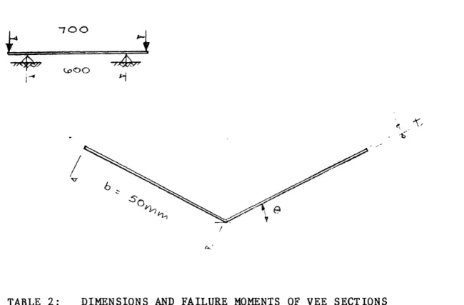
The general set up of the test rig used in these investigations is shown in
applied uniform moment to a beam over the central span. For most of the tests
the central span was set at 700 mm, but this could be varied as required.
A total of 115 tests were carried out on sections of general plain channel
shape, having the flang~s either perpendicular to the webs or at some angle 9
to the webs. Of these tests, 91 were carried out on channels bent in such a
way that bending caused compression of the flange free edges, and 24 were
bent in the opposite direction, i.e., causing tension of the flange free
edges.
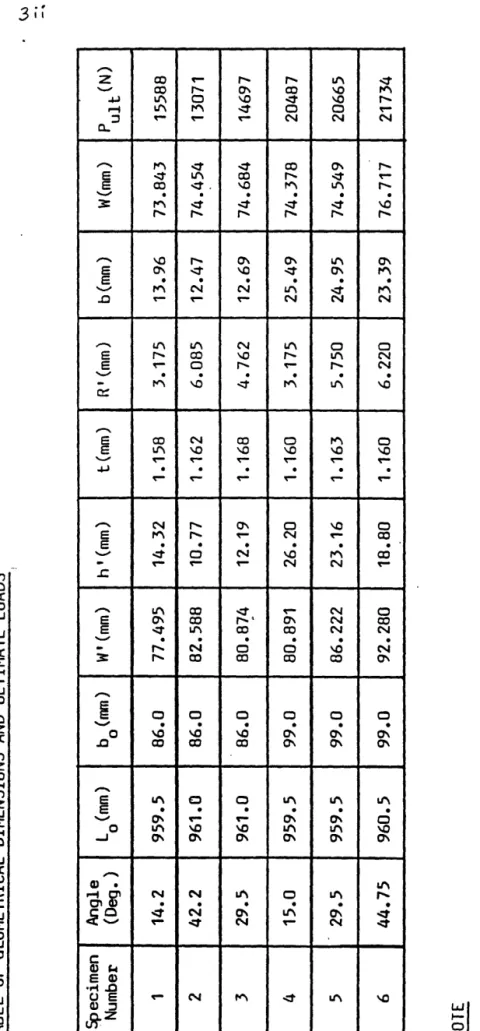
Details of the specimens tested and the experimental failure moments are
given in TABLE 1. Specimens which have T appended to their number were
tested with the flange free edges in tension.
A total of 36 tests were also carried out on Vee sections with large ~ngles
between the legs of the Vee. These tests were carried out largely to examine
the effects of large corner angles on the section behaviour, (as were some of
the channel tests), and the tests were carried out on a modified test rig
similar to that used for the channels. Of these tests half were carried out
in bending to cause compression of the free edges of the elements, and half
in the reverse direction. The dimensions and failure moments of these
sections are given in TABLE 2. In this table the letters .. C" and •'1'11
used in
the section number specify the free edge compression or tension conditions
under the test loading. All specimens were manufactured in the University,
and for each different sheet of material used tensile test specimens were cut
8
-Typical moment-deflection curves are shown in Figures 6, 7 and 8 for channels
having flange perpendicular to the webs. For relatively thick material,
Figure 6, the nonlinearity near the maximum moments is due to plasticity,
while for very thin material, Figure 8, the nonlinearity is due to local
buckling. For the deeper sections in this figure local buckling occurs
theoretically at a moment of around 20 Nm, and this indicates the high degree
of postbuckling capacity. The deflections recorded here were the total
deflections, including deflections of the overhangs between supports and end
loads. An indication of the effects of flange angle from the vertical is
given in Figure 9, for angled channels.
Figure 10 shows non dimensional values of experimental failure moment for all
channel section tests where the flange angle is 60° or less and the flange
free edges are in compression. Also shown on this figure are values of fully
plastic and first yield moments for different flange/web ratios. Points
immediately apparent from this figure are:
I. The specimens tested can withstand the full first yield moment if the
flange width to thickness ratio is less than about 29. This indicates
significantly greater strength than given in most current design codes.
2. For flange width to thickness ratios less than about 16 the fully
plastic moment, or greater resistance, was attained. No design code for
cold formed steel known to the writer permits any degree of compression
these tests indicate partial plastic capacity for b/t up to 29, and full
plastic capacity for b/t less than 16 for the conditions considered.
Comparisons of the experimental failure moments with those predicted using
the British Code a~d the European Recommendations are shown in Figure 11.
The predictions of both codes are over conservative. The AISI code cannot be
used to examine this case as the effective width in that code is governed by
the stress at the supported edge, which for this case, tensile.
Figure 12 shows comparisons of the experimental failure loads with the
proposed design rule of this report. This is as follows for b/t > 30
where o-'eR.
and
Qe
-b
for the plain channels considered
The expressions for ~CR and K are taken from the British Code. The ~CR
expression is simply obtained using standard buckling formulae and the
material constants for steel. The expression for K was derived in the course
of the work reported here. From Figure 12 it may be claimed that the design
formulae give reasonably good, slightly conservative estimates of failure for
members with b/t > 30.
For relatively thick members, i.e, b/t < 30, the effects of post compression
yield can be taken into account using an elasto-plastic stress distribution
-10-buckling in the flange. A perhaps simpler approach is to use an interaction
formula in the range where ~CR is greater than Ys. The interaction formula
suggested is
for
~R>
o-'y M UL.\::.where Mp is the fully plastic moment, My is the moment to cause first yield
and MULT is the ultimate moment. The failure predictions obtained using this
equation are given in Figure 12, showing conservative agreement with test
results.
The effects of large corner angles is shown in Figure 13. This plots the
comparison of failure moments obtained using the design approach proposed
here with the results of those tests which were carried out on specimens with
large corner angles. As may be observed from the figure, at corner angles
less than about 60°, the experimental results are in good agreement with the
design predictions. For greater corner angles the experimental results are
less than those predicted by the design analysis. This was expected, due to
the high order effects which arise for large corner angles, and is the
subject of a continuing research project. However, from the results shown it
can be stated that the design rules proposed are adequate for corner angles
of 45° greater than the right angle, with something in reserve.
In the case of unstiffened elements bent in such a way that the free edges
are in tension, the results obtained showed that a partially plastic failure
criterion, as used in the European Recornmendatio'ns, is applicable. This is
illustrated in Figure 14 which shows variation of experimental failure moment
with variation in flange-web angle. The proposed design procedure in this
The stress distribution was assumed to be elasto-plastic as illustrated in
the figure and failure was assumed when the stress on the effective width of
the compression element reached Ys. The effective width was evaluated using
the expression given in Section 5 with the buckling coefficient for the
compression element taken as 5.34 as calculated theoretically.
As may be observed the design rules predicted the maximum moment with some
conservatism for corner angles less than about 50°. For large corner angles,
as expected the predictions are non-conservative. This graph also therefore
justifies a limit of 45° corner angles for safe application of the design
rules.
Although the failure moments are predicted accurately by the methods
described here, for thin elements the experimental deflections before failure
could be substantially greater than predicted using the effective width
approach. This can be explained on the basis of two strain investigations
carried out on sections bent to cause compression of the flange free edges.
In these investigations, strain gauges were laid on one flange as indicated
in Figure 15. Readings of the strains for specimen No 18, of relatively
thick material, and specimen No 32, of very thin material, are shown in
Figures 16 and 17. The variation of strain on the tension side very
adequately shows the significant movement of the neutral axis towards the web
as predicted by the effective width approach. On the compression side,
however, for the thinner element, the large buckling deformations affect the
strains (and stresses) very substantially. So much so that for the thinner
element of Figure 17, at high moments, the strain and stress on the
-12-also very noticeable at the point of maximum strain, and indeed the maximum
membrane strain is much less than the yield value when failure occurs. This
is in agreement with theoretical analysis, and indicates that failure occurs
due to the combination of membrane and out of plane bending stresses reaching
yield. Under these conditions, although an effective width approach can give
accurate predictions of failure it is not really modelling the failure
mechanics. To investigate this further, a plastic mechanism analysis was
employed whereby plastic failure was assumed to occur at "hinge lines'' as
illustrated in Figure 18. This produced very good agreement with
experimental results. However, since the effective width approach gives
simple and accurate assessments of failure load, and no clear way could be
seen to produce quite so simple equations using the mechanism approach it was
decided not to pursue this approach with regard to design analysis at the
present time.
3 • EDGE STIFFEBED ELEMEJITS
Edge stiffeners are used to avoid the problems of early buckling which arise
in unstiffened elements, and to make such elements behave as if they were
stiffened. In order to achieve this an edge stiffener must have a specified
minimum flexural rigidity. Until recent years it was assumed that the
required flexural rigidity of an edge stiffener was such that it increased
the buckling coefficient of its associated element to be equal to that of a
stiffened element. This is now known to be an unsatisfactory and insufficient
criterion. For elements which have an edge stiffener, an adequate stiffener
must support the edge not only at the point of buckling, but throughout the
In the research reported here theoretical and experimental investigations
were initially carried out on individual elements. The stiffener rigidities
required for such elements were substantially greater than those used in
design codes and it became clear that the support from adjacent elements had
a substantial effect on the required stiffener rigid~_ty. Further- series of
tests were carried out on edge stiffened elements as parts of compressed
sections and as elements of beams.
3.1 Outline of theoretical approach
In the theoreti~al investigation of edge stiffened elements th~ semi-energy
method approach was again used. The possibility of plate initiated buckling
(local buckling) and stiffener initiated buckling (torsional buckling)
occurring either individually or simultaneously was considered. The types
of buckling and the nomenclature used are illustrated in Figure 19. In order
to simulate the effects of adjacent elements it was assumed that rotations of
the supported edge of the element were resisted elastically, with the
rotational stiffness, R, being different for the local mode than for the
torsional mode as occurs in actual sections. Full details of the
investigation are given in Ref (1), and only the general findings are
mentioned here. These are:
1. For elements with simply supported edges the buckling loads obtained
from the analysis were in fairly good agreement with, as indicated in
Figure 20, but less than those obtained by Kloppel (10). This
-
14-2. In consideration of a single half wavelength of the torsional buckling
mode it was found that there were strongly directional effects, i.e.,
buckling in one direction was easier than in the opposite direction.
The directionality was affected by the edge stiffener geometry and by
the presence of loca 1 buckling.
3. The minimum resistance to torsional (stiffener initiated) buckling of a
given edge stiffened element is extremely dependant on the restraint
against rotation of the supported edge. If this edge is simply
supported then the torsional buckling load decreases with increase in
length of the element, and the minimum buckling load of an edge
stiffened element eventually becomes less than that of an unstiffened
element. This seemingly strange result had been earlier found by Bulson
(11). It follows from this that the adjacent elements of a section, and
the loading applied tp the section, have a substantial effect on the
buckling load of the edge stiffened element.
3.2 Experimental investigation
In the experimental investigation of edge stiffened elements tests were
carried out on individual elements with simple right angle lips, elements
with angled lips and elements with compound lips. Tests were also carried
out on compressed sections having elements with simple and compound edge
stiffeners and on beam sections with simple lip edge stiffeners. Apart from
one series of compression members with simple lips all elements and sections
were manufactured in the University. Tensile test specimens were cut and
analysed on the basis of the true yield stress for that specimen. The types
of elements and members tested are illustrated in Figure 21.
To test individual elements a test rig was designed and manufactured in the
University. This test rig is shown diagramatically in Figure 22 and
different elevations and cross-sections in Figure 23. Detail drawings have
been omitted. This test rig accommodated L shaped specimens of total length
985 mm and overall width 75 mm. Three holes were drilled at the top and
bottom of each specimen and the specimen was fixed to the loading heads of
the test rig through these holes. Thus in the te·gt the specimen ends were
fixed, and the free length of element between the supports was 915 mm. The
supported edge was held in place by knife edge supports which provided simple
support conditions. In the case of elements with simple lip edge stiffeners
the specimens were manufactured with 5 different lip widths of nominal
dimensions 0, 6.25 mm, 12.5 rom, 18.75 mm and 25 mm.
To facilitate measurement of deflections of these specimens, and to examine
the initial imperfections of the specimens a deflection measuring device
-DMD - was designed and manufactured in the University. This device was
designed to provide a magnified plot of deflection against distance along the
specimen. The DMD is shown in Figure 24. This consists of a linearly
variable differential transformer (LVDT) which is used as a contact probe,
positioned in a holder which is mounted onto two longitudinal stainless steel
tubes and can move freely along these tubes. The longitudinal tubes are 1n
turn mounted on transverse tubes at each end, so that the probe can be
positioned at any point in a plane. The frame of the DMD is made of slotted
-
16-or sh16-orter tubes and framing angle. The position of the contact probe along
the longitudinal tubes is measured by a position transducer. The contact
probe is moved remotely by means of a wire and pulley arrangement through a
handle positioned along one of the edge framing angles. This ensures that
measurement of the deflections is accomplished without applying any force to
--the specimen o--ther than --the spring force of --the contact probe. The signals
from contact probe and position transducer are fed to an XY plotter to
produce a plot_ of deflection distance along the specimen. During test the DMD
was attached to the test rig through its slotted angle frame.
The DMD was made with easy adjustability so that this device could be used
with a variety of test rigs, and this allowed the use of this device with
subsequent compressed section tests and intermediately stiffened element
test.s.
The stiffened element tests were carried out in the Tinius Olsen test
machine. A total of 75 tests were carried out on elements with simple right
angled lip stiffeners. A further 6 tests were carried out on angled lip
stiffeners and 24 tests were carried out on compound lip stiffeners, making a
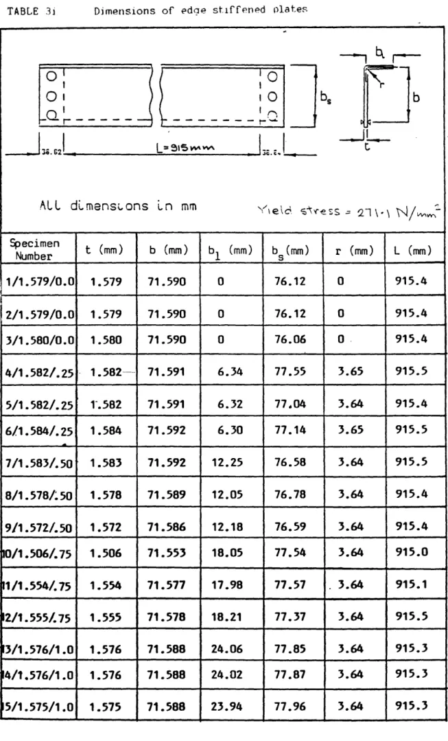
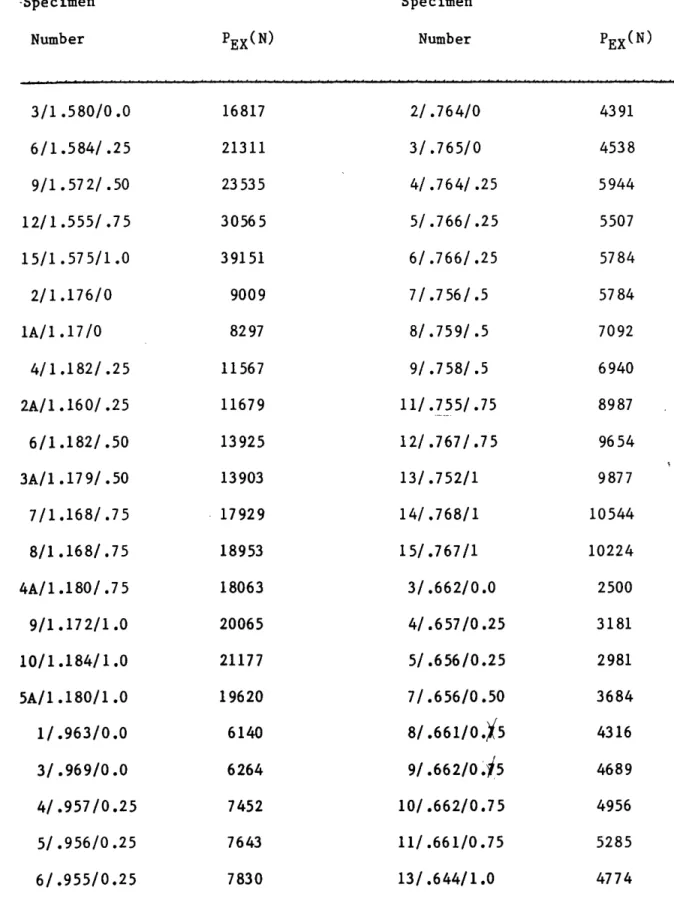
total of 105 tests on individual elements. The specimen dimensions and
failure loads are given in TABLE 3.
Figure 25 shows typical measurements of initial imperfections in the
torsional and local modes measured on an unloaded specimen by the DMD.
Figure 26 to 28 show typical variations of deflections along the centre line
small thickness and large lips, and in such a case local buckling, indicated
by the short wavelength deflections, occurs initially. Failure in these
cases is largely due to local buckling.
The specimens of Figure 27 have no lip and~~ very small lip, and here
torsional buckling in a single half wave occurs. Note that the end fixity is
clearly shown. It is also of note that the specimen with no lip shown here
developed shorter have wavelength buckles on the long wavelength buckle as
loading progressed.
The specimens shown in Figure 28, despite having relatively large lips,
underwent torsional buckling initially. It is of interest to note from this
figure that torsional buckling does not produce immediate failure, and in
fact there can be a substantial post-torsional buckling range. It is also of
interest to note that, as predicted theoretically, local buckling can occur
after the elements have buckled torsionally.
Figure 29 shows plots of load against end shortening obtained from a series
of specimens having the same material thickness and different lip sizes. The
full lines shown in this figure were directly obtained from the Tinius Olsen
test machine plotter and the various dots and other symbols represent the
results of dial gauges which were used to check various aspects of the
machine measurement system. As would be expected, increasing the stiffener
size increases the load capacity.
Figures 30 and 31 show comparisons of the theoretical and experimental
18
-On one specimen a strain investigation was carried out. Two bands of strain
gauges were positioned on the specimen at the locations shown in Figure 32.
The top band location was specified to coincide with a position on the
specimen where the local imperfections had a maximum value, and the bottom
b a n d w a s 1 o c a t e d on t h e m i d- 1 e n g t h of t h e s p e~ei m en. E a c h b a n d o f g a u g e s
consisted of 10 two gauge rosettes placed on each side of the material, from
which membrane strains and stresses could be obtained. The total number of
gauges used in the two bands was 80.
Figures 3-J and 34 show the variation of stresses obtained from the strain
gauge read~ngs for a number of applied loads. The specimen examined was of
thin material and had a large lip. The well known effects of reducing stress
towards the centre of the main element and towards the free edge of the lip
are clearly observed. It may also be observed that the stresses at the
lip-main element junction are slightly less than those at the supported edge.
This is due to small out of plane deformations of the junction.
The variation of experimental failure loads with variations in element width
to thickness ratio is shown in Figure 35. The failure loads are plotted in
non-dimensional form. Main points of note from this figure
are:-1. For all material thicknesses the failure load increases with increase in
lip size until the lips are large in width. For lip sizes of
approximately one quarter of the plate width and one third of the plate
width the failure stresses are similar for most of the range. Thus for
the elements tested the required lip width for adequate support is about
width to thickness ratios, where there is still some increase in failure
stress as the lip size increases. Thus for adequate support the lip
sizes for thicker elements require to be somewhat larger than quarter of
the element width.
2. For the highest b/t ratio tested, i.e, 108, the non dimensional
experimental failure loads show a reduction from those which would be
expected, and the curves show a downward trend. This caused some
speculation as to whether there was some unforeseen problem with the
test rig, or some high order effects which became:manifest at this
stage. However, the major reason for the low failure stresses for this
b/t ratio lies simply in the fact that the material of this thickness
which was used had a very lo·w yield stress, 174 N/mm 2 , in comparison
with all the other material thicknesses.
3.2.2 Coapression members
In order to examine the effects of adjacent elements on the behaviour of edge
stiffened elements, tests were carried out on outwardly turned lipped
channel, or top hat section compression members. A total of 22 specimens
were tested, 18 having simple lip stiffeners and 4 having compound lip
stiffeners. For the simple lip specimens, all specimens had flanges and webs
of 77 mm nominal width. Three different thicknesses of material were used
and for each thickness 6 different lip widths were tested ranging from 0 to
32 mm in approximately equal steps. Details of the specimen geometries and
-
20-The specimens were tested between flat plattens in the Tinius Olsen test
machine, and the test arrangement is shown diagrammatically in Figure 36.
Prior to test the ends of the formed specimens were carefully milled and
ground to ensure a flat and plane surface perpendicular to their longitudinal
axe. s. A 1 u m in i u m p 1 a t e s o f 0 • 8 m m t h i c k n e s s w e r
e--
g 1 u e d t o t h e ope n e n d s o fthe specimens using quick setting Araldite 2002. This procedure had been
carried out on earlier tests of thin-walled sections, and proved successful
in eliminating any slight irregularities in the specimen ends which may still
exist after machining and in ensuring that the specimen ends did not warp.
Strain gauges were attached to each specimen at ~id height in ~he_ positions
indicated in Figure 37. These gauges were used to ensure that uniform
compression was applied across the section, to determine the local buckling
load if required, and to assess the behaviour of the stiffener-flange
junction for future study. The strain gauge results are not presented in
this report, but are available in Ref (1) if required.
Out of plane deflections of the edge stiffened element were measured at the
position shown in Figure 38. The deflection plots at different loads are
shown for all specimens of a single thickness in Figures 39-41. As for the
individual elements it can be observed that small lips do not prevent long
wave torsional buckling deflections whereas with larger lips these are
prevented, and short wave local buckles are more in evidence.
3.2.3 Bending •embers
The behaviour of edge stiffened elements under bending such that the edge
stiffeners are in tension is well known, and needs no examination. In the
case of elements bent to cause compression of the edge stiffeners, however,
some investigation was considered worthwhile.
a
series of tests weretherefore carried out on top hat sections loaded as beams in which the edge
stiffeners were subjected to compression.
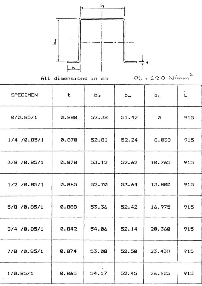
This series consisted of 8 tests on top hat sections having nominal flange
and web dimensions of 52 mm and of thickness 0.87 mm. The lip dimensions
were varied from zero to 27 mm. Complete dimensions of the specimens tested
are given in TABLE 6.
The specimens were tested under 4 point bending on the bending test rig used
for the examination of unstiffened elements, with the edge stiffened elements
comprising the bending elements, and the loading applied such that the
stiffeners were in compression.
Two of these specimens failed by local crushing of the webs. This type of
failure was avoided in the remainder of the tests by providing more
substantial load spreaders at the supports and loading points. Typical
moment-deflection curves are shown in Figures 42 and 43, and the failure
loads of all specimens are given in TABLE 7.
3.3 Formulation of design approach
To facilitate the formulation of a set of rules governing the behaviour of
-
22-procedure the torsional buckling behaviour of an edge stiffened element was
assumed to consist of rotation about the supported edge as illustrated in
Figure 44. This rotation is resisted by elastic restraining forces R as
shown in the figure, where R is equal to M b
e'D
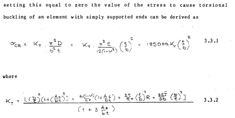
By evaluating the total potential energy of the system, minimising and
setting this equal to zero the value of the stress to cause torsional
buckling of an element with simply supported ends can be derived as
'2.
= I
'8500~ ~-jet)
3.3 .1
where
3.3.2
In this expression As is the stiffener area, D is the plate flexural rigidity
factor and
I
is the equivalent stiffener flexural rigidity.For a lip stiffener of width b 1
2 '2.
b 1-5 b
"'1
+-L1 bt
3.3.3'2.. "t.
where
Is
is the stiffener second moment of area about the plate middle surface. The numerator of the expression for KT is obtained from the bendingenergy of plate and stiffener, and the denominator is obtained from the
potential lost by the applied loading. If the stiffened element has
undergone loca 1 buckling prior to torsional buckl ing_ .. _the numerator remains
unchanged. The denominator changes, and to take this into account it is
assumed that the effects of local buckling are to induce an effective width
of the main element, beff which is equal to r,
b ,
and an effective area ofstiffener, Ae. If the plate effective portions are equally situated at both
edges as shown in Figure 45 then
3.3.4
In the case of the individual elements examined, with simply supported loaded
edges, R = 0 and the expression for
Kr
can be written- '2_
3E.l (9)
Db t.
3.3.5
If it is assumed that failure accompanies torsional buckling then the
torsional buckling stress must be equal to, or greater than the material
yield stress if the stiffener is adequate
r'-ThUS 185000
(t)
kT
J.
y5
1.e
K.r ::.
3.3.6-
24-Nominating this value of KT as Ky and rearranging the governing expression
for
K.r
givesI
Db
For a lip stiffened plate, this can be rewritten
3 .3. 7
3.3.8
3
Note that in the formulation of the above equation the term (Af>) was
"-bt
omitted, as this has quite a small value for normal stiffener dimensions.
Note also that as 1/b increases the numerator increases so that for very long
elements the required stiffener rigidity becomes extremely large. This is
due to the lack of restraint on rotation of the supported edge of the plate.
For the unstiffened elements tested the end supports were fixed. Therefore
the effective length should be taken as half the total length. However,
since full fixity cannot be achieved it was decided to take the effective
length as 0.6 times the total length.
-Equation 3.3.8 cannot be solved directly because As, Ae and I are
interdependent. However this equation can be solved very quickly by
iteration methods to yield the required value of I for a given set of
conditions. Knowing the value of
I,
the corresponding value ofIs
and thecorresponding minimum lip width can be obtained using equation 3.3.3 and the
relationship
By this means the minimum required value of the rigidity of an edge
stiffener, and the minimum lip width, can be obtained to provide adequate
support to the stiffened edge. For elements having adequate support then
stiffened plate design analysis can be used.
For elements without an edge stiffener the failure loads and stresses can be
obtained using unstiffened element analysis.
For elements having stiffeners which have rigidity less than adequate the
failure load lies between the unstiffened and stiffened element analyses, and
to establish the behaviour of such elements examination of the experimental
results is beneficial.
Figures 46 t~ 50 show the variations of ultimate loads obtained
experimentally (plotted in non-dimensional form) from the tests on 5
different thicknesses of elements, In each figure, two curves, are also
shown. The curve to the right of each figure is for adequate stiffener
analysis, and starts from the minimum required lip width and plots the
ultimate load using the stiffened element analysis given in this report. The
curve to the left of each figure is for inadequate stiffener analysis and is
a straight line drawn from the calculated capacity of an unstiffened element
(with h=o) to the point where the stiffener is just adequate and stiffened
element analysis can be employed. These curves show quite good agreement
with the experimental ultimate loads in all cases, both for adequate and
-
26-In the case of elements of compression members, which is the practical
condition, interaction betwPen elements arises, and torsional buckling of an
edge stiffened element is generally resisted, this resistance being specified
by the coefficient R. The act of restraining the supported edge prevents the
torsional buckling stress from decreasing indefinitely with increase in
length, and a minimum value of Kr arises at a particula·r 1/b ratio. The
maximum value of
Kr
can be determined by differentiating equation 3.3.2. withrespect to R, thus obtaining the value of 1/b at which the minimum KT 1s
obtained, and thereafter substituting this 1/b value into equation 3.3.2. to
get
KrMrN·
Now by setting KrMIN equal to Ky the following minimum stiffenerrigidity requirement is obtained.
-I ::
In the presence of local buckling the term (
by equation 3.3.4.
3.3.10
1 + ~ ~r ) is replaced as given
bt
Performing this replacement and considering the case of lip stiffeners yields
the following expression
3 .3 .11
It should be mentioned here that owing to the simplified deflected form used
in this analysis the above equation only holds if the value of R is not very
torsional buckling conservative evaluation of the magnitude of R can be
obtained on the basis of simple beam analysis which gives
3.3.12
where bz is the width of the web of the section as indicated in Figure 51.
Equation 3.3.11. can be solved iteratively to evaluate the minimum required
stiffener rigidity, and lip width for a given section geometry.
Comparison of the failure loads for top hat sections of different material
thicknesses is shown in Figure 51. The curves to the right of the figure are
for adequately stiffened sections and those to the left are for inadequately
stiffened elements. In deriving these curves the same procedure was used as
for the individual elements discussed previously. The unstiffened element
loads were obtained, for the case h=o, on the assumption that K=0.425.
The agreement between the theoretical and experimental failure loads is in
general very good, therefore it can be claimed that the approach used
accurately models the behaviour of edge stiffened elements. However,
equation 3.3.11, which requires an iterative solution, cannot be said to be
"simple11
, and some simplification would be beneficial.
From equation 3.3.11. it can be seen that the coefficient R has a significant
effect on the required stiffener rigidity, and as R depends on section
geometry it is therefore the case that the required stiffener rigidity
depends on section geometry rather than on the individual element which is
-
28-3.4 Finite strip investigation
As design codes at present takes no account of section geometry effects it
was decided to further check this conclusion using finite strip analysis.
The finite strip approach used only considered the initial buckling load, and
could not therefore be used directly to take the effects of local buckling on
torsional buckling into account. However this can be accomplished indirectly
using equation 3.3.4. This equation can be rearranged to give a
multiplication factor to relate, approximately, values obtained on the basis
of neglect of local buckling effects to the corresponding values which take
local buckling into account.
The rearrangement gives
1-<'y- y
'Y\I.q (
e:, 4'1
2
-
~ ~)
+ 3~.£
1 + 3 ~s
bt:
where KR is a ficticious yield coefficient.
3.3.13
In the finite strip analysis, three different edge stiffened elements were
considered_,(!) an element of a channel having web width equal to twice the
flange width.(2) an element of a channel having equal flange and web widths,
I
and (3) an element fully fixed on its supported edge. The edge stiffened
elements in each case had a "simple" lip of width one fifth of the element
width.
Figures 52, 53 and 54 show comparisons of the torsional buckling loads for
the fact that in each case the element in question is identical the
differences in torsional buckling resistance are great. The required minimum
buckling coefficient for an adequate stiffener is shown in each case. The
fixed edge element is more than adequately stiffened in all circumstances.
The element of the square channel is inadequately stiffened for the largest
width to thickness ratio while the 2:1 channel is only just adequately
stiffened for the smallest width to thickness ratio. This clearly
demonstrates the difference in stiffness requirements for different
geometries of section.
3.5 Design rules
In the light of the findings to date, it can be said that for accurate
assessment of stiffener adequacy some method of taking the interaction
between different elements into account should be used. Equation 3.3.11 does
·this, but requires an iterative solution and so is not very suitable for
design. To make this equation more suitable, use can be made of the fact
that it is a very quickly converging equation, and so as an initial guess it
can be assumed that the ratio of stiffener to plate area is equal to 0.2.
Substituting this into equation 3.3.11 gives a solution of acceptable
accuracy on the first iteration. To make the solution simpler and at the
same time to apply a small degree of conservatism the term of unity at the
extreme right hand side of equations 3.3.10 and 3.3.11 can also be neglected.
The quantity Ky can also be written in the form
b \ 2
Ys ( :z- _;
-1 ~50 0 0
-
30-Substituting this into equation 3.3.10, performing the simplications
mentioned and rounding the resulting numerical factors in such a way that
conservatism is assisted, yields the following design equation corresponding
to equation 3.3.10 for an element not subject to local buckling.
=
10 I'< 3.5.2To cover the situation when the element has buckled, a very simple
approximation to thi.~ffective width of a stiffened element is used, i.e, for
b/t > 40 then be= 40/(b/t).
Assuming also that the stiffener effective area can be given by Ae = 0.2 x
-
-bet, for the purposes of setting up the equation results in the equation, for
an element subject to local buckling, b/t > 40.
I
t.4' =
'2.
Q
S
~s [ _ib;t_)t L2<BO 10 ooo -+ 3.5.3
Equations 3.5.2 and 3.5.3 cover the case of locally unbuckled and locally
buckled elements. If b/t is about 12.65 then I = 0, and for elements of
lower width to thickness ratios no stiffener is required.
In the stiffener adequacy equations b is the flat width of the element and IA
is the second moment of area of the stiffener about the plate middle surface.
The restraint coefficient, R, is taken as given by equation 3.3.12, i.e,
2b
b'2.
where b is the width of the element to be stiffened and b2 1s the web width.
The value of R should not be taken as greater than 6 in any circumstances.
Also, R need not be taken as less than 0.4 if there is a web to resist
twisting of the edge stiffened element. Note that these rules apply only to
an element which has a web on its supported edge. Comparison of the
predictions of these rules, together with the other design rules proposed in
this report, with the experimental findings of the investigation on channels
are given in Figure 55, (identical to Figure 51)_, which shows good a~~eements.
The prescribed stiffener rigidities given here are quite substantially
different from those of both the AISI specification and the European
Recommendations, which are both very similar, following from the research of
Desmond, Pekoz and Winter(ll). Quite apart from the fact that these
specifications do not differentiate between the stiffener requirements for
different section geometries, the actual requirements are substantially
different for a typical case.
In the case of thin elements, the requirements of the European
Recommendations are based largely on test results. However, as mentioned
previously, in order to assess the results of tests it is not only the
specific element under examination which contributes to the behaviour, but
also the other elements of the section, so that the apparent results of
element examination are dependant on the complete design approach used.
In order to further assess the validity of the equations produced here,
-
32-examination of the experimental results of Desmond et al(ll) was carried out.
Comparison of the experimental failure loads of Reference (11) with the
calculated failure loads using the adequacy requirements and other design
formulae of this report is shown in Figure 56. The agreement is fairly good
in a 11 c a s e s. F o r t h e s p e c i mens of E- 2 3 • 9 and E- 21 .4 , b a c"K in g p 1 a t e s w e r e
glued and rivetted to the webs to make the webs fully effective. If the webs
are fully effective the analysis results slightly overestimate the load
capacity, as shown in the Figure. Since the backing plate was very thin,
re-analysis was undertaken assuming that the backing plate behaves as a
stiffened element. ··The resulting analytical failure loads, shown by the
dotted curves for these specimens, are close to·the test loads.
It may be also considered that the stiffener adequacy requirements set out in
equation·s 3.5.2 and 3.5.3 can be applied with adequacy for any loading
condition, if Ys is replaced by 05.where ~Sis the stress on the stiffener at
failure. Thus in the case of elements loaded in combined bending and axial
load, if the stress on the stiffener is greater than that at the supported
edge then 0"8 = Y8• If the stress on the stiffener is less than that at the
supported edge then ~S < Y8, and the stiffener rigidity required for
adequacy is reduced. In the case of sections bent in such a way that the
stiffener is in tension, then no stiffener is required for the element to
behave as a stiffened element, and this was borne out by the results of the
tests carried out on plain channels loaded to cause compression of the web.
In the case of stiffeners bent in such a way that the stiffeners are in
compression then at failure cr's = Ys and the adequacy requirements are as
this way highlighted important differences for such a case. For a light
gauge element with an edge stiffener under bending as shown in Figure 57, the
stresses are relayed to the edge stiffener via shearing forces at the element
stiffener junction, as indicated. In such a case there is the tendency for
the stiffene-r to bend in plane and the· stress system indu.ced across the
stiffener varies from tension to compression as shown in the figure, even if
the stiffener is perfectly adequate.
Under these conditions the load carried by the stiffener is equivalent to the
,. ...
load carried by the uniformly stressed stiffener of width one quarter of the
actual stiffener width. If the bending was applied in such a way as to cause
tension in the stiffeners then beam action would counteract this effect and
nullify this tendency, thus inducing more or less fully effective stiffeners.
However bending which causes compression of the stiffeners does not inhibit
this tendency and indeed may tend to exacerbat~ this types of behaviour.
The failure moments on channel beams obtained from the tests which caused
compression of the edge stiffeners are shown in Figure 58 in comparison with
the ultimate moments calculated using the stiffener adequacy requirements
given here and assuming that the lips are either completely effective or only
25% effective. The 6 tests in this series which were not affected by web
crippling are shown here, and as can be observed the 4 specimens with
adequate stiffeners failed at loads very close to those obtained on the basis
of 25% effective stiffeners. Thus this hypothesis is confirmed, and in
design only 25% of the stiffener width should be counted for such a case. It
is also noteworthy that in the case of inadequate stiffeners the straight
-
34-stiffener does not seem to hold in this case, and if the 34-stiffener is
inadequate then for safety its contribution should be discounted completely.
4. INTERMEDIATELY STIFFENED ELEMENTS
Intermediate stiffeners are used to reduce local buckl~ng effects in
stiffened elements by using stiffeners to rntntmtse deflections at the
stiffener location. The general nature of the behaviour of intermediate
stiffeners has substantial similarities to that of edge stiffeners, 1.e, the
stiffeners requtre to have a certain m1n1murn rigidity if they are to fulfill
their function prop~rly. As with edge stiffeners, early research
concentrated on specifying the stiffener rigidity required to support the
stiffener location at buckling. However, the work of Desmond (12) showed
that, as with edge stiffeners, this is not the correct criterion. Instead,
an adequate intermediate stiffener must support its associated plate elements
until local plate failure occurs, which may be at a load less than or greater
than the buckling load of the stiffened sub-element.
The research carried out in this programme involved theoretical analysis of
stiffened elements with a single intermediate stiffener, and experimental
investigations of the behaviour of simply supported intermediately stiffened
elements in compression and of beams having intermediately stiffened
compression elements.
4.1 Outline of theoretical approach
The main theoretical approach again used the semt-energy method. The cross
section of the intermediately stiffened element studied was of the form shown
and 60(b) were considered. One half of an intermediately stiffened element
was analysed, assuming symmetry about the stiffener centre line with regard
to stiffener initiated buckling, and anti-symmetry with regard to plate
initiated buckling as indicated in Figure 61.
As in the case of edge stiffeners it was found that directional effects arose
with regard to the stiffener buckling behaviour, and these were affected by
the presence of local buckling. For intermediate stiffeners the effects of
rotational restraint on the element edges is not so pronounced as for edge p"';
stiffeners, and for long intermediately stiffened element-s the stiffener
buckling mode may consist of several waves rather than a single half
wavelength.
4.2 Experimental Investigations
Two main investigations were made into the experimental behaviour of
intermediately stiffened elements; one investigation into individual elements
and the other into compression elements of beams. All specimens tested were
manufactured in the University, and tensile tests were made on all sheets of
material used in their manufacture. The types of elements and members tested
are shown in Figure 62.
It was required, for both investigations, that stiffeners of a variety of
different depths be formed in the specimens. To accomplish this a press rig
was made up using hot rolled channel and T beams. The general arrangement of
the press rig is shown in Figure 63, and cross-sectional views are shown 1n
-
36-width from 6 mm to 11 mm and of any desired depth and used the Tinius Olsen
test machine to provide the following loads.
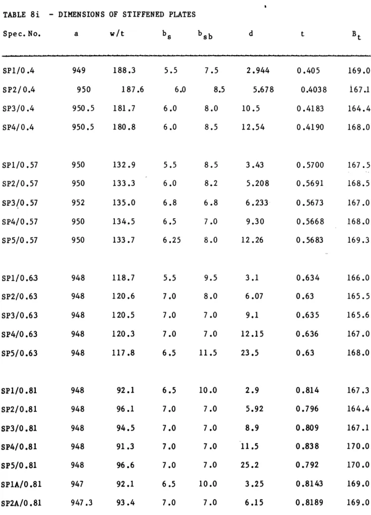
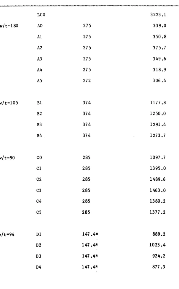
4.2.1 Individual Elements
A total of 42 individual elements were testea to failure, 35 intermediately
stiffened elements and 7 elements without intermediate stiffeners. The
geometry of the elements is shown in Figure 65 and all elements were
nominally 950 mm in length. Details of the dimensions of the elements are
given in TABLE 8.
"•"\
A test rig was designed and manufactured in the University for testing of the
elements. This rig was built to apply uniform compression to elements of
length between fixed ends of 950 mm and width between knife edge supports of
160 mm. An isometric view of the test rig is shown in Figure 66 and plan and
elevations are shown in Figure 67. A typical set of load-end shortening
curves for specimens of a single thickness is shown in Figure 68. The
stiffener depths for the specimens shown here varied from 2.9 mm to 25.2 mm,
and the plots show that the strength and stiffness of the element increased
as the stiffener depth increases. It should be mentioned here that as the
stiffener depth increases the element cross-sectional area increases, so that
part of the increase in load capacity is simply due to increase in
sectional area. For example, in this figure the specimen SP5 had a
cross-sectional area 15% to greater than that of specimen SP4. While the total
failure load of SP5 was 26% greater than that of SP4, the increase in
efficiency was therefore much less.
elements. The deflections of a flat element without an intermediate
stiffener are shown in Figure 69. This shows that from an initially
imperfect condition the element developed more or less symmetrical buckles,
approximately equal in half wavelength to the total width between knife edge
supports. For small depth stiffeners Figure 70 shows that stiffener
initiated buckling occurs, with three half wavelengths over the element
length. With slightly larger stiffeners, Figure 71, local buckling and
stiffener buckling, are both present. The local buckles have less than half
the wavelength of those in the flat plate while the stiffener buckle half
wavelength has increased so that now only two half wavelengths occur rather
than three as for the smaller stiffeners. It is noteworthy that the local
buckles increase in amplitude where the stiffener buckling deflections are
upwards in Figure 71, and decrease in amplitude when the stiffener buckling
deflections are downwards. This is due to the fact that the stiffener
buckling upward~ increases the plate stresses, while downward buckling of the
stiffener decreases the plate stresses. This is part of the directionality
effect mentioned earlier. With larger stiffeners the buckling is mainly
local, as shown in Figure 72. However, as is found theoretically, it is in
general not possible for local buckling to occur without also inducing
overall deflections.
For two specimens strain gauge investigations were undertaken. Each
investigation used 56 gauges laid in two bands across one symmetrical half of
the element. Layout of the gauges for one test are shown in Figure 73 and
the position of the strain gauge bands are shown superimposed on a plot of
the deflections along the specimen tested in Figure 74. Band (1) and Band