This is a repository copy of
A Schur Complement Method for DAE Systems in Power
System Dynamic Simulations
.
White Rose Research Online URL for this paper:
http://eprints.whiterose.ac.uk/108779/
Version: Accepted Version
Proceedings Paper:
Aristidou, P orcid.org/0000-0003-4429-0225, Fabozzi, D and Van Cutsem, T (2014) A
Schur Complement Method for DAE Systems in Power System Dynamic Simulations. In:
Domain Decomposition Methods in Science and Engineering XXI. 21st international
conference on domain decomposition methods in science and engineering, 25-29 Jun
2012, Rennes, France. Springer Verlag , pp. 719-727. ISBN 9783319057880
https://doi.org/10.1007/978-3-319-05789-7_69
Reuse
Unless indicated otherwise, fulltext items are protected by copyright with all rights reserved. The copyright exception in section 29 of the Copyright, Designs and Patents Act 1988 allows the making of a single copy solely for the purpose of non-commercial research or private study within the limits of fair dealing. The publisher or other rights-holder may allow further reproduction and re-use of this version - refer to the White Rose Research Online record for this item. Where records identify the publisher as the copyright holder, users can verify any specific terms of use on the publisher’s website.
Takedown
If you consider content in White Rose Research Online to be in breach of UK law, please notify us by
A Schur Complement Method for DAE Systems
in Power System Dynamic Simulations
Petros Aristidou1, Davide Fabozzi1, and Thierry Van Cutsem2
1 Introduction
Power system dynamic simulations are widely used in industry and academia to provide important information on the dynamic evolution of a system after the oc-currence of a disturbance. In modern dynamic simulation software there is the need to represent complex electric equipment that interact with each other directly or through the network. These equipment models represent generators, motors, loads, wind generators, compensators, etc. with all the physics involved and the required controls. This multi-domain modeling leads to large, non-linear, stiff and hybrid (i.e. subject to both continuous and discrete dynamics) Differential and Algebraic Equation (DAE) systems [10].
In these dynamic simulation studies, the speed of simulation is of the utmost importance. The observations resulting from these simulations can be critical in scheduling corrective actions to guard the actual power system against instability. This procedure, called real-time Dynamic Security Assessment, is performed by many power system companies.
Triggered mainly by the developments in parallel processing technologies, some DDMs have already been proposed to speed up simulations. They are mainly based on Schwartz alternating methods and Waveform Relaxation methods [9, 7, 11]. Un-like space domain decomposition, no geometrical information is given to decom-pose a DAE system [5] and engineers have to rely on a priori information on the sys-tem’s topology and operation for partitioning. Furthermore, alternating algorithms demand great care in the partitioning of the system and the handling of interface values to ensure the convergence of the methods [1, 8]. If tightly coupled unknowns are mapped to different partitions and an alternating procedure is used, significantly slowed down convergence rates or divergence can be experienced [2].
This paper proposes a robust, accurate and efficient parallel algorithm based on the direct Schur Complement DDM [13]. The algorithm yields significant accelera-tion when compared to classic, high performance, integrated (applied on the unde-composed system) dynamic simulation algorithms. The two-fold gain comes from utilizing the parallel potential of the method and exploiting the locality and sparsity of power systems. Furthermore, as a direct method, convergence does not depend on the specific partitioning of the system as the interface values are resolved accurately at each step before solving the sub-domain problems. A connection between the
1Department of Electrical Engineering and Computer Science, University of Li`ege, Li`ege,
Bel-gium, e-mail:[email protected]·2Fund for Scientific Research (FNRS) at the
De-partment of Electrical Engineering and Computer Science, University of Li`ege, Li`ege, Belgium, e-mail:[email protected]
2 Petros Aristidou, Davide Fabozzi, and Thierry Van Cutsem
proposed algorithm and quasi-Newton based integrated algorithms is demonstrated allowing the better comprehension of the algorithm’s properties. Finally, an imple-mentation of the algorithm using the shared-memory parallel programming model and some numerical results are presented based on a realistic large-scale test system. The paper is organized as follows: in Section 2 we present the partitioning scheme of the proposed algorithm. In Section 3, we explain the formulation of the dynamic simulation problem and the solution using the Schur Complement method. In Section 4, some further investigation of the algorithm is made with the help of quasi-Newton integrated algorithms. Implementation specifics and simulation study are reported in Section 5 and followed by closing remarks in Section 6.
2 Power System Modeling
An electric power system, under the phasor approximation [10], can be described in compact form by the following DAE Initial Value Problem:
0 =ΨΨΨ(x,V)
Γ
ΓΓx˙ =ΦΦΦ(x,V)
x(t0) =x0,V(t0) =V0
(1)
whereVis the vector of voltages through the network,xis the expanded state vector containing the differential and algebraic variables (except the voltages) of the system
andΓΓΓ is a diagonal matrix withΓΓΓℓℓ=
{
0, if theℓ-th equation is algebraic 1, if theℓ-th equation is differential. The first part of system (1) corresponds to the purely algebraic network equa-tions. The second part describes the remaining DAEs of the system. Discrete events (caused by digital controllers, load tap changing devices, etc.) can alter the power system equations during the simulation. The handling of these discrete events is not presented in this paper [4].
2.1 Power System Partitioning
Fig. 1 Decomposed Power System:The Power System is decomposed into the Network and the injectors connected to it. This reveals a star shaped decomposition layout with the Network sub-domain connected to all other sub-domains.
Network
M M
M
M
Γix˙i=Φi(xi,V
ext)
0=Ψ(xext
,V)
V
Injectors
The network sub-domain is described by the algebraic equation system (2) while the sub-domain of each injectoriis described by the DAE system (3).
0=ΨΨΨ(xext,V)
xext(t0) =xext0 ,V(t0) =V0 (2)
Γ
ΓΓix˙i=ΦΦΦi(xi,Vext)
xi(t0) =xi0,Vext(t0) =Vext0 (3)
Sub-domains numbered 1, . . . ,M−1 relate to injectors andMrelates to the network. Vectorsxiand matricesΓΓΓiare the projections ofxandΓΓΓ, defined in (1), on thei
sub-domain. The variables of each sub-domain are separated into interior (int) variables appearing only in equations of the sub-domain itself and interface (ext) variables appearing in equations of both the Network and an injector sub-domain. Thus, for injectorsxi= [xinti xexti ]and for the NetworkV= [VintVext](see Fig. 1).
3 DDM-based Algorithm
3.1 Local System Formulation
Each injector DAE sub-system is algebraized and the resulting non-linear systems of equations are solved with a quasi-Newton method. The local linear systems involved in the solution take on the form of (4) for the injectors and (5) for the network.
[ A1iA2i A3iA4i
]
| {z }
[
△xinti △xexti ]
| {z }
+[0 Bi
] | {z }
[ 0 △Vext
]
=
[
finti (xinti ,xexti )
fexti (xinti ,xexti ,Vext)
]
| {z }
Ai △xi Bei fi
4 Petros Aristidou, Davide Fabozzi, and Thierry Van Cutsem
[ D1D2 D3D4
]
| {z } [
△Vint △Vext
]
| {z }
+∑Mj=−11[0 Cj
] | {z }
[ 0 △xextj
]
=
[
gint(Vint,Vext)
gext(Vint,Vext,xext)
]
| {z }
D △V Cej g
(5)
whereA1i (resp.D1) represents the coupling between interior variables.A4i(resp. D4) represents the coupling between local interface variables.A2iandA3i(resp.D2
andD3) represent the coupling between the local interface and the interior variables
and,Bi(resp.Cj) represent the coupling between the local interface variables and
the external interface variables of the adjacent sub-domains.
3.2 Global Reduced System Formulation
To formulate the global reduced system involving only the interface variables, the interior variables of the injector sub-domains are eliminated from (4), which yields for thei-th injector:
Si△xexti +Bi△Vext=˜fi (6)
whereSi=A4i−A3iA1−i1A2iis thelocalSchur complement matrix and ˜fi=fexti − A3iA−1i1finti the corresponding adjusted mismatch values.
Contrary to matrices Ai, which are small but dense and general, matrix D is
large but sparse and structurally symmetric. Thus, eliminating the interior variables from (5) would destroy its sparsity and symmetry. Therefore, all the variables of the network sub-domain are included in the reduced system (7).
S1 0 0 · · · 0 B1 0 S2 0 · · · 0 B2 0 0 S3 · · · 0 B3
..
. ... ... . .. ... ... 0 0 0 · · ·D1D2 C1C2C3· · ·D3D4
△xext1 △xext2 △xext3
.. .
△Vint △Vext
= ˜ f1 ˜ f2 ˜ f3 .. . gint gext (7)
Due to the star layout of the decomposed system (see Fig. 1), the resulting global Schur complement matrix in (7) is block bordered diagonal. Manipulating this struc-ture we can further eliminate all the interface variables of the injector sub-domains and keep only the variables associated to the network sub-domain, as shown in (8).
The elimination factorsCiS−i 1Biaffect only non-zero elements of sub-matrixD4
[
D1 D2
D3D4−∑i=N−11CiS−i 1Bi
]
| {z }
[
∆Vint
∆Vext ]
| {z }
=
[
gint
gext−∑Mi=−11CiS−i1˜fi
]
| {z }
e
D ∆V eg
(8)
3.3 Exploiting Locality
The procedure can be further accelerated by exploiting the locality of the sub-domains. Some sub-domains, described by strongly non-linear systems or with fast changing variables, converge slower. Other sub-domains, with “low dynamic activ-ity”, converge faster. This can be exploited in two ways.
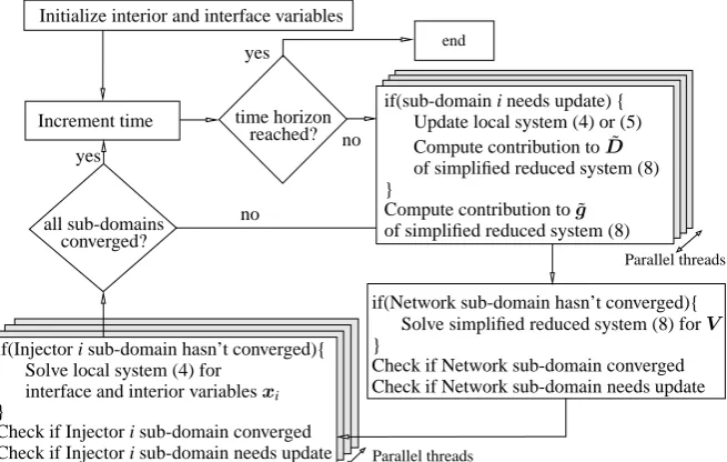
[image:6.595.160.467.82.144.2]First, subdomains with low dynamic activity are detected by measuring the ef-fort (number of Newton iterations) needed for convergence at each discrete time. A subdomain’s system is updated if that effort increases above a threshold. Second, a subdomain is declared converged (and stops being solved within the discrete time) if the absolute maximum normalized correction of a Newton solution of the subdo-main system becomes smaller than a selected tolerance. Since the low dynamics are detected numerically during the simulation and the tolerance is chosen small enough so as not to disturb the Newton solution, the accuracy of the solution is preserved. Figure 2 shows the full parallel algorithm.
Parallel threads
Parallel threads Increment time
end
all sub-domains converged?
time horizon reached? yes
yes
no
no
if(Injector i sub-domain hasn’t converged){ Solve local system (4) for
interface and interior variablesxi }
Check if Injector i sub-domain converged Check if Injector i sub-domain needs update
if(sub-domain i needs update) { Update local system (4) or (5) Compute contribution to ˜D
of simplified reduced system (8) }
Compute contribution to ˜g
of simplified reduced system (8)
if(Network sub-domain hasn’t converged){ Solve simplified reduced system (8) forV
}
Check if Network sub-domain converged Check if Network sub-domain needs update Initialize interior and interface variables
[image:6.595.139.467.374.582.2]6 Petros Aristidou, Davide Fabozzi, and Thierry Van Cutsem
4 Further Analysis of the Algorithm
To better understand its properties, Algorithm (P) in Fig. 2 can reformulated into an equivalent quasi-Newton undecomposed scheme with thek-th iteration described:
Ak1
1 0 · · · 0 Be k1 1
0 Ak2
2 · · · 0 Be k2 2
..
. ... . .. ... ... 0 0 · · ·AkM−1
M−1 Be kM−1
M−1
e
Ck1M Cek2M · · ·CekM M−1 DkM
k
| {z }
△x1 △x2
.. .
△xM−1 △V k
| {z }
=− f1 f2 .. . fM−1
g k
| {z }
+ r1 r2 .. . rM−1
rM k
| {z }
˜Jk △yk Fk rk
yk+1=yk+△yk
where 0≤kj≤k(j=1, ...,M)and ri =
{
fi, ifi-th sub-domain has converged 0, otherwise.
The approximate Jacobian ˜Jk is used by the method at each iterationk. Every block lineiof ˜Jkcorresponds to a sub-domain and is updated independently based on sub-domain update criteria [4]. Thus, some block lines can be kept constant for several iterations or even time-steps (ki≤k).
Furthermore, sub-domains considered to have converged are not solved any more (see Fig. 2). In the equivalent quasi-Newton integrated scheme this corresponds to explicitly setting the mismatch of those sub-domains to zero by introducing some inaccuracy to the method through the correction termrk. The inaccuracy is bounded
and controlled to avoid affecting the accuracy of the final solution.
Using this formulation for Algorithm (P) allows us to utilize a general and well developed framework within which quasi-Newton schemes involving inaccuracy can be described and analyzed [12, 3].
5 Implementation and Numerical Results
The Schur Complement-based DDM was implemented in the simulation software RAMSES, developed at the University of Li`ege. The benchmark Algorithm (I) is a quasi-Newton scheme applied to the undecomposed DAE system (1). It uses an ap-proximate Jacobian which is updated and factorized if the system hasn’t converged after three Newton iterations at any discrete time instant. This method (also referred to as Very Dischonest Newton Method) is considered to be one of the fastest se-quentialalgorithms and many traditional industry software use it.
ma-lators, power system stabilizers, speed governors and turbines. Additionally, 7211 models are included involving induction motors, dynamically modeled loads and equivalents of distribution systems. The resulting, undecomposed, DAE system has 146239 states. The disturbance simulated consists of a short circuit near a bus last-ing 5 cycles (100 ms at 50 Hz), that is cleared by openlast-ing a double-circuit line. The system is then simulated over a period of 240 s with a time step of 1 cycle (20 ms).
Fig. 3 Speedup index:
time elapsed sequential algorithm (I) time elapsed parallel algorithm (M cores)
This index shows how faster is the parallel implementa-tion when compared to the fast sequential integrated Algorithm (I) on the same computer.
0 0.5 1 1.5 2 2.5 3 3.5 4 4.5 5 5.5
1 2 4 6 8 10 12 14 16 18 20 22 24 0 100 200 300 400 500 600 700 800
Speedup
elapsed time (s)
# of cores Algorithm (I)=663s Elapsed Time - Alg. (P)
Speedup - Alg. (P)
[image:8.595.270.458.419.543.2]The same models, algebraization method (second-order Backward Differentia-tion Formula) and way of handling the discrete events are used in both algorithms. For the solution of the sparse linear systems, HSL MA41 [6] is used and for the dense injector linear systems of Algorithm (P), Intel MKL LAPACK library. The computer used for the simulation is a 24-core, shared memory, AMD Opteron Inter-lagos (CPU 6238 @ 2.60GHz) running Debian Linux.
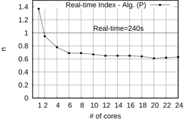
Fig. 4 Real-time index:
n=simulation elapsed time
simulated physical time
This index shows how faster was the simulation than the simulated time. This is an important index for control center applications where the speed of computation is an
issue for operator decision. 0 0.2 0.4 0.6 0.8 1 1.2 1.4
1 2 4 6 8 10 12 14 16 18 20 22 24
n
# of cores Real-time=240s Real-time Index - Alg. (P)
Figure 3 shows that the DDM-based algorithm is already twice faster than the benchmark in sequential execution. This speedup is mainly attributed to the ex-ploitation of locality in the decomposed algorithm (Section 3.3). As we proceed to parallel execution, the proposed algorithm performs up to 4.5 times faster. Figure 4 shows the real-time potential of the algorithm in parallel execution.
se-8 Petros Aristidou, Davide Fabozzi, and Thierry Van Cutsem
quential portion of the code and the parallel portion of the code. A higher ratio leads to better speedup and avoids the saturation observed when increasing the number of cores. The size of the interface system (8) is the same as of the network subdo-main (5), that is approx. 30 000 for the test-system considered. At the same time, the subdomain systems include approx. 120 000 states. Thus, the size ratio is approx. 4, which explains why a relatively small speedup is observed after 6 cores and the speedup saturates at 4.5 times.
6 Conclusion
In this paper a Schur Complement-based algorithm for dynamic simulation of elec-tric power systems has been outlined. The algorithm yields acceleration of the simu-lation procedure in two ways. On the one hand, the procedure is accelerated numer-ically, by exploiting the locality of the sub-domain systems and avoiding many un-necessary computations (factorizations, evaluations, solutions). On the other hand, the procedure is accelerated computationally, by exploiting the parallelization op-portunities inherent to DDMs.
References
1. Crow, M., Ilic, M., White, J.: Convergence properties of the waveform relaxation method as applied to electric power systems. In: Circuits and Systems, 1989., IEEE International Symposium on, pp. 1863 –1866 vol.3 (1989)
2. CRSA, RTE, TE, TU/e: D4.1: Algorithmic requirements for simulation of large network ex-treme scenarios. Tech. rep. URLhttp://www.fp7-pegase.eu/
3. Dennis, J., Walker, H.: Inaccuracy in quasi-Newton methods: Local improvement theorems. Mathematical Programming at Oberwolfach II22, 70–85 (1984)
4. Fabozzi, D.: Decomposition, Localization and Time-Averaging Approaches in Large-Scale Power System Dynamic Simulation. Ph.D. thesis, University of Li`ege (2012)
5. Guibert, D., Tromeur-Dervout, D.: A Schur Complement Method for DAE/ODE Systems in Multi-Domain Mechanical Design. Domain Decomposition Methods in Science and Engi-neering XVII pp. 535–541 (2008)
6. HSL(2011): A collection of Fortran codes for large scale scientific computation. URLhttp: //www.hsl.rl.ac.uk
7. Ilic’-Spong, M., Crow, M.L., Pai, M.A.: Transient Stability Simulation by Waveform Relax-ation Methods. Power Systems, IEEE Transactions on2(4), 943–949 (1987)
8. Jackiewicz, Z., Kwapisz, M.: Convergence of waveform relaxation methods for differential-algebraic systems. SIAM Journal on Numerical Analysis33(6), 2303–2317 (1996)
9. Kron, G.: Diakoptics: the piecewise solution of large-scale systems. MacDonald (1963) 10. Kundur, P.: Power system stability and control. McGraw-hill New York (1994)
11. La Scala, M., Bose, A., Tylavsky, D., Chai, J.: A highly parallel method for transient stability analysis. Power Systems, IEEE Transactions on5(4), 1439 –1446 (1990)