Design and Analysis of Miniaturized Low Profile
and Second-Order Multi-Band Polarization
Selective Surface for Multipath
Communication Application
HUI WANG 1, LIN ZHENG1, MINGBAO YAN 1, JIAFU WANG1, SHAOBO QU1, AND RUITAO LUO2
1Department of Basic Science, Air Force Engineering University, Xi’an 710043, China 2University of Nottingham Ningbo, Ningbo 315100, China
Corresponding author: Hui Wang ([email protected])
This work was supported in part by the National Natural Science Foundation of China under Grant 61331005, Grant 61471388, Grant 61501502, and Grant 61771485, and in part by the National key R&D Program of China under Grant 2017YFA07002015.
ABSTRACT In this paper, a novel frequency selective surface (FSS) is designed; it has the character-istics of the low profile, second-order, multi-band, and the remarkable polarization selection properties. In the following, such an FSS having polarization selection characteristics will be referred to simply as a polarization selection surface (PSS). In a specific frequency band, the proposed PSS has a second-order selective transmission characteristic for TE and TM waves. Based on the coupling resonance filtering mechanism, the proposed PSS is composed of three metallic layers separated by two layers of dielectric substrates, which serves as the spatial form of the second-order microwave filter. The proposed PSS uses a sub-wavelength periodic structure array consisting of a non-resonant unit, and the unit size and the period within the range of 0.08λ1–0.15λ1, where theλ1=40.76 mm is the first passband wavelength of free space,
so the PSS miniaturization characteristic is remarkable. The theoretical analysis and measure results show that the proposed bandpass PSS has good second-order polarization selection characteristics, out-of-band suppression level, and the flat transmission band, compared with the first-order bandpass PSS. In the range of incident angle of 0◦–60◦, it has a stable frequency response. It provides a reference for the design of a polarization wave generator and a polarization separation structure in a multipath communication system.
INDEX TERMS Angle stability, frequency selective surface, polarization selective, second-order, multi-band.
I. INTRODUCTION
Frequency selective surface (FSS) is a spatial microwave filter. It shows obvious filtering characteristics, can make the electromagnetic wave totally reflect or transmit at the resonance frequency [1]–[4].
At present, FSS has been widely used in the research and design of stealth antenna radome [5], composite absorb-ing materials [6]–[7], polarization mode converters [8], composite multi-frequency antenna design [9] and multipath communication system [10]. As we all know, modern com-munication satellite system is a typical multipath commu-nication system, which can serve users in multiple bands at the same time. In the system, FSS is used as a sub-reflector
of the communication antenna, enabling multiple pairs of feeds to work at the same time. For example, it can realize dual-frequency or multi-frequency sharing functions such as X/Ku, S/X or S/X/Ku/Ka bands [11]. Also, it has selective effect on electromagnetic wave polarization mode in its oper-ating frequency. However, there are little researches on FSS polarization selection characteristics [12], [13]. In practical application, in order to weaken the influence of complex electromagnetic environment, resist active jamming, sup-press environmental clutter and improve its detection abil-ity. Polarization wave generators or polarization separation structures are needed in satellite communication systems to generate single-mode polarization waves or separate different
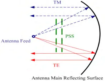
polarization modes, so as to load communication informa-tion by using single-mode polarizainforma-tion waves in different wavebands. Therefore, the study of FSS with polarization selection characteristics is of great significance for the design of polarization wave generator or polarization separation structure [14]. The working principle of polarization selective antenna in communication satellite system is shown in Fig.1.
FIGURE 1. The working principle of polarization selective antenna.
In Fig.1, the antenna feed and the polarization selective surface (PSS) are placed on the concave surface of the main reflecting paraboloid, assuming that the feed operates in the C-band and X-band. The incoming wave can pass though the PSS operating in C-band for TE mode while in X-band for TM mode. That is, PSS transmission surface can select and transmit TE polarized electromagnetic signals and TM polar-ized electromagnetic signals excited by the feed. Through PSS, single-mode polarized waves of different wave bands can be generated, which greatly enhances the use function of communication satellites.
In [15], it proposes a kind of PSS with polarization separation function. When the capacitive surface and the inductive surface with complementary structures have lat-eral displacement along the periodic arrangement direction, the PSS becomes a polarization separation structure with TM bandpass and TE bandstop. In [16], based on electromagnetic resonance theory, a novel PSS is designed by loading lumped LC devices into periodic arrays. The designed structure has good polarization separation characteristics near the specific frequency. In the range of 0◦-40◦, the structural transmission characteristics of TE and TM polarization are stable. Based on the design theory of metamaterial structures, [17] proposes two layers of PSS and one-sided PSS, both of which can simultaneously realize the first-order selective transmission of TE and TM waves in a specific frequency band.
However, the above designs based on traditional FSS also need to be improved. Firstly, the size and thickness of tra-ditional FSS to achieve the required transmission character-istics is too large, which makes it very difficult to apply it to satellites with limited space. Secondly, the angle stability of the above designs are good in the range of 0◦-40◦, but in practical application, it is important to keep a in a wider
angle range. Thirdly, the above designs ar a first-order filter response, its bandpass response is not flat enough, its band-width is narrow, and it cannot provide a good level of out-of-band suppression, so it is not enough to meet the needs of satellite communication.
In order to solve these problems, it is necessary to design PSS with high order bandpass and large angle sta-ble response. Conventionally, higher-order bandpass FSS is designed by cascading a plurality of first-order FSS panels with a dielectric substrate loaded with a quarter of the work-ing wavelength. Thus, a flat bandpass response is obtained, and cascading multiple bandpass FSS panels can expand bandwidth and ensure stable transmission characteristics. However, this kind of multi-panel structure is thick and heavy, which is not suitable for practical engineering design. In order to reduce the longitudinal dimension (i.e. total thickness and profile) of the multi-panel structure, some scholars at home and abroad have successively studied and proposed to design a bandpass FSS based on the coupling resonance filtering mechanism: R. Pous and D. M. Pozar first proposed a method based on ‘‘patch - aperture - patch’’ coupling to design FSS with low profile and higher-order transmission response [18]. In [19]–[22], FSS based on the structure of substrate inte-grated waveguide cavity is proposed, which is used to achieve low profile and higher order transmission response. K. Sara-bandi and N. Behdad studied the transmission response of FSS based on sub-wavelength structure (or metamaterial) and realized the resonance of long wavelength controlled by small size structure through the coupling between sub-wavelength units [23]–[32].
Therefore, the bandpass FSS panels based on the cou-pling resonance filtering mechanism have stable and excel-lent transmission performance through cascade coupling of thin-layer media, can realize low profile and higher-order wide-band filtering characteristics, and can also suppress grating lobes and maintain large angle stability. The coupled FSS does not need to maintain a panel spacing of 0.2λ’ - 0.3λ’ like the traditional multi- panel FSS structure,λ’ represents the center frequency wavelength of the operating frequency band, thus maintaining a good low profile characteristic.
Using printed circuit board technology, the prototype was fabricated and measured. The measure results are in good agreement with the simulated ones.
II. DESIGN OF POLARIZATION SELECTIVE SURFACE
[image:3.576.352.540.152.386.2]Based on the coupling resonance filtering mechanism, FSS is synthesized from a second-order band-pass microwave filter topology. FSS is a multilayer structure composed of a periodic structure with effective inductance, capacitance and resonant surface impedance and two thin dielectric substrates. In the following design process, a FSS design is given and discussed.
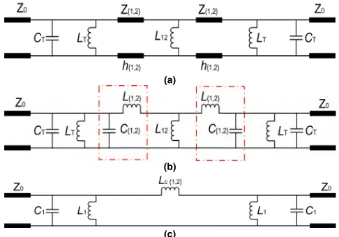
FIGURE 2. (a) The equivalent circuit model of the second-order bandpass filter used in this paper. (b) The simplified LC equivalent network is used to represent the equivalent circuit of the transmission line. (c) Typical circuit model of second-order coupled resonant filter after T-π
transformation.
Fig.2(a) shows the topology of a second-order bandpass fil-ter, which is the basis of the proposed second-order bandpass FSS. The filter is composed of two resonators separated from inductorL12by two short transmission lines, each resonator
is composed of parallelLCcircuits (LT andCT). The short
transmission line has a characteristic impedance ofZ{1,2}and
a total length of h{1,2}. The free space on both sides of the
filter is modeled as a semi-infinite transmission line with characteristic impedance of Z0 = 377. Fig.2(b) shows
a simplified equivalent circuit model using the simple LC
equivalent networks (L{1,2}andC{1,2}) shown in the red box
instead of the filter transmission line in Fig.2(a).The circuit model shown in Fig. 2(c) is obtained by converting the induc-tive T network into aπ network. In [33], a general method for constructing the N-order coupled resonant bandpass filter model is proposed. From [33] it can be seen that the circuit model shown in Fig.2(c) is a typical topology with a second-order coupled resonant bandpass filter. Therefore, the model shown in Fig.2(a) is sufficient to achieve the second-order bandpass response.
In order to design the target FSS, the values of the compo-nents used in the equivalent circuit model of Fig.2, should be optimized, which will produce the required response, using
the approximate synthesis formula provided in this section. These values can then map out the physical and geometric parameters of the structure. Referring to [33], we assume that the center frequency isf0, the relative bandwidthδ=BW/f0,
the working bandwidthBW, and the normalized quality factor
Qare all known. Using these parameters, the values of the components can be obtained, as follows:
C1 = q
ω0Z0δ
(2.1)
L1 =
1
ω2(C
1−K1,2·δ·C1)
(2.2)
Lc{1,2} =
1
ω2
0·K1,2·δ·C1
(2.3)
L12 =
2L12
3L1+Lc{1,2}
(2.4)
L{1,2} =
L1·Lc{1,2}
3L1+Lc{1,2}
(2.5)
C{1,2} = ε0
·εr{1,2}·h{1,2}
2 (2.6)
Z{1,2} =
Z0 √
εr{1,2}
(2.7)
h{1,2} =
L{1,2} µ0·µr{1,2}
(2.8)
CT =C1−
ε0·εr{1,2}·h{1,2}
2 (2.9) whereK1,2 represents the normalized coupling coefficient
between the two resonators in Fig.2(a),Lc{1,2}represents the
coupling inductor of the equivalent circuit model in Fig.2(c),
εr{1,2} andµr{1,2} represents the relative dielectric constant
and the relative permeability of the dielectric substrate, respectively. Using the above expression, the initial value is given to for optimization, and the value of the components used in the equivalent circuit model can be obtained.
Since FSS is a spatial microwave filter, the second-order coupled resonant bandpass filter topology discussed above can be used to synthesize the second-order bandpass FSS. The filter shown in Fig.2 can be considered as an equivalent circuit model of the second-order bandpass FSS of the normal inci-dent plane electromagnetic wave. The required FSS structure itself can be directly synthesized from the equivalent circuit shown in Fig.2(a).The structure consists of three metal layers separated from each other by two thin dielectric substrates. By mapping component parameter values to physical param-eters, the two transmission lines of Fig.2(a) are implemented using two F4B-2 thin dielectric substrates with a thickness of h=1 mm, a dielectric constant ofεr =2.65, and a loss
tan-gent of 0.001.To generate second-order polarization selection response, the top and bottom metal layers are composed of a periodic array of asymmetric Jerusalem crosses for realizing parallelLCcircuits (LTandCT). The copper clad thickness on
the dielectric substrate was 0.017 mm, where X=3.25 mm, Y=6.25 mm, L1=0.5 mm, L2=5.5 mm, L3=2.5 mm,
L4 = 0.5 mm, P = 3 mm, Q = 0.25 mm, as shown
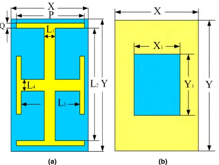
[image:3.576.35.278.223.393.2]FIGURE 3. Schematic diagram of each layer structure of the synthesized PSS. (a) Top and bottom metal layer structures. (b) Intermediate metal layer structures.
FIGURE 4. Three-dimensional topology of synthesized PSS.
and the blue part represents the dielectric substrate. Since the side length of these capacitive patches is much shorter than half a wavelength, these structures are non-resonant, and their periodic arrangement only presents a capacitive impedance to incident waves. The intermediate metal layer is composed of a metal square aperture for realizing the inductorL{1,2}
in Fig.2(a), as shown in Fig.3(b), where X1 =2.25mm and
Y1 = 2.75 mm. This metal layer presents the inductive
impedance to the incident waves. Fig.4 shows a synthesized three-dimensional topology of the proposed PSS.
For the novel PSS structure shown in Fig.4, when TE and TM waves are normally incident along the +Z direc-tion, simulation is carried out using CST microwave studio electromagnetic simulation software. The S-parameter curves are shown in Fig.5, in which S21represents the transmission
curve and S11represents the reflection curve. As can be seen
from Fig.5, the proposed PSS structure realizes the separation of the polarization waves of the two modes when TE and TM waves are incident. The selective transmission of polarized waves in two modes is realized simultaneously in specific band, and a good second-order response is further achieved. Among them, the resonance frequency of TE passband is
f1 = 7.36 GHz and f3 = 26.75 GHz, respectively, and the
resonance frequency of TM passband isf2=11.45GHz.
FIGURE 5. S-parameters curves of PSS at normal incidence of TE and TM waves.
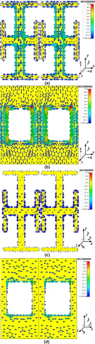
In order to understand the principle of polarization selec-tion and resonance, the induced current distribuselec-tion of PSS at two resonance frequencies f1 = 7.36GHz and f2 =
11.45GHz are given in Fig.6 and Fig.7, respectively. The arrow indicates the direction of the current, while the color indicates the relative magnitude. The darker the color is, the greater the current intensity is.
Fig.6(a) and Fig.6(b) show the current distribution on the asymmetric Jerusalem cross structure and the intermediate metal layer, respectively, when TE waves are normally inci-dent and at f1 = 7.36 GHz. Figs.6(c) and 6(d) show the
current distribution of asymmetric Jerusalem cross structure and intermediate metal layer, respectively, when TM wave is normally incident and atf1 = 7.36 GHz. As can be seen
from Fig.6(a) and Fig.6(b), asymmetric Jerusalem cross and intermediate metal layer have a strong current distribution in the y- direction. As can be seen from Fig.6(c) and Fig.6(d), the current distribution on the asymmetric Jerusalem cross and the intermediate metal layer is very weak, and it can be neglected in both the x- and y- directions. In addition, it can be seen that the excitation of the current in the y-direction causes the polarization wave of TE mode to be transmitted. Furthermore, since the current flows in the y-direction in Fig.6(a) and Fig.6(b) are opposite, it is obvious that a first-order resonance occurs between the asymmetric Jerusalem cross and the intermediate metal layer. Moreover, there is a strong electromagnetic coupling between the top and bottom metal layers and the intermediate metal layer, so the transmission pole point of PSS is caused by coupling resonance. Whenf3=26.75 GHz, the transmission principle
of TE mode polarized wave is the same asf1=7.36 GHz.
Similarly, Fig.7(a) and Fig.7(b) show the current distri-bution on the asymmetric Jerusalem cross structure and the intermediate metal layer when TE wave is normally incident at f2 = 11.45 GHz. Fig.7(c) and Fig.7(d) show the
cur-rent distribution of asymmetric Jerusalem cross structure and intermediate metal layer when TM wave is normally incident atf2=11.45GHz. As can be seen from Fig.7(a) and Fig.7(b),
[image:4.576.43.268.291.403.2]FIGURE 6. When f1=7.36 GHz, the current distribution of the top and bottom metal layers and the middle metal layer under the normal incidence of TE and TM waves. (a) TE mode, the current distribution of the top and bottom metal layers. (b) TE mode, the current distribution of the intermediate metal layer. (c) TM mode, the current distribution of the top and bottom metal layers. (d) TM mode, the current distribution of the intermediate metal layer.
have a strong current distribution in the x-direction. Thus, it is concluded that the excitation of the current in the x-direction causes the TM polarization wave to be transmitted.
FIGURE 7. Whenf2=11.45 GHz, the current distribution of the top and bottom metal layers and the middle metal layer under the normal incidence of TE and TM waves. (a) TE mode, the current distribution of the top and bottom metal layers. (b) TE mode, the current distribution of the intermediate metal layer. (c) TM mode, the current distribution of the top and bottom metal layers. (d) TM mode, the current distribution of the intermediate metal layer.
[image:5.576.79.235.61.626.2]cross and the intermediate metal layer. Moreover, there is a strong electromagnetic coupling between the top and bottom metal layers and the intermediate metal layer, so the transmis-sion pole point of PSS is caused by coupling resonance.
From the above analysis, it is concluded that the long and the short arms of the asymmetric Jerusalem Cross play a key role in the transmission selection of TE and TM waves, respectively. Therefore, using structural asymmetry to transmit polarized waves provides a new design idea for the designing of polarization wave generator and polarization separation structure.
III. ANALYSIS OF FACTORS INFLUENCING PSS TRANSMISSION CHARACTERISTICS
From S-parameters curve shown in Fig.5, it is observed that the insertion loss of the three passbands is less than 0.5dB. The −3dB transmission bandwidths are 1.57GHz (6.50GHz-8.07GHz) and 3.04 GHz (25.42GHz-28.46GHz) for TE wave under normal incidence while the−3dB trans-mission bandwidth is 2.98GHz (9.90GHz-12.88GHz)for TM wave. The relative bandwidths are 21.33 %, 11.36 % and 26.03%, respectively. The first pass band of PSS is presented with free space wavelength ofλ1 = 40.76mm, thus its
ele-ment size is in the range of 0.08λ1-0.15λ1, the miniaturization
characteristic of PSS is remarkable. For each passband, its falling edge is steeper, and the amplitude of the transmission coefficient will change by not less than 8dB for every 1GHz, indicating that the three transmission windows have high fre-quency selectivity and out-of-band suppression level. In the first frequency band of 6.50GHz-8.07GHz, the lowest reflec-tivity of TE wave can reach−40dB, and the transmission rate of TM wave is less than−12dB. In the frequency range of 25.42GHz-28.46GHz, the reflectivity of TE wave can reach
−39dB at the lowest, and TM wave has no transmission in this passband. In the frequency range of 9.94GHz-12.88GHz, the lowest reflectivity of TM wave can reach−40dB, and the transmission rate of TE wave is less than−12dB. Therefore, this miniaturized PSS achieves good bandpass polarization selection characteristics for TE and TM waves in a specific frequency band.
A. INFLUENCE OF INCIDENCE ANGLE ON TRANSMISSION
In the subsection, the angle stability of the proposed PSS structure to polarized waves in different modes is analyzed by simulating the incident of TE and TM waves with different incident anglesθfrom 0◦to 60◦. Other parameters of PSS are
unchanged. Incidence angleθis defined as the angle between the+Z direction and the wave vector k. The transmission and reflection curves for TE and TM wave incidence are shown in Fig.8.
[image:6.576.315.515.63.563.2]It can be seen from Fig.8(a) and Fig.8(b), the passband does not shift when TE wave is incident in the range of 0◦-60◦ angle of incidence, and the position of the center frequency in the passband is basically unchanged. And with the increase of incident angle,−3dB bandwidth decreases slightly and out-of-band suppression capability increases slightly. Because for
FIGURE 8. The transmission and reflection curves of TE and TM waves incidence at different angles.
TE waves, there are [34]–[37]:
ZTE =Z/cosθ, Q=ZTE· p
C/L (3.1) In the formula (3.1),θ is the incidence angle, andC,L are equivalent capacitance and equivalent inductance of PSS structure respectively, and Z is equivalent impedance of PSS structure when electromagnetic wave is incident normally. When TE wave is incident, the equivalent impedance ZTE
value is inversely proportional to the TE passband bandwidth, the TE passband bandwidth of the proposed PSS structure is reduced.
From Fig.8(c) and Fig.8(d), it can be seen that, in the range of 0◦- 60◦angle of incidence, the passband moves slightly to high frequency when TM wave is incident. However, when the incident angle is increased from 15◦to 60◦, grating lobes appear at high frequencies. Because they are far away from the working frequency point and their transmission rates are less than−10dB, they will not interfere with the polariza-tion selective filtering characteristics of PSS.As the incident angle increases, the bandwidth slightly increases, and the out-of-band suppression capability decreases. Because for TM waves, there are [34]–[37]:
ZTM =Z·cosθ, Q=ZTM· p
C/L (3.2) In the formula (3.2), when TM wave is incident, the equiv-alent impedance ZTMdecreases with the increase of incident
angle θ, and the Q value decreases with the decrease of ZTM. Since the Q value is inversely proportional to the TM
passband bandwidth, the TM passband bandwidth of the pro-posed PSS structure increases. Simulation results show that the proposed PSS has good angle stability and polarization selection characteristics for polarized waves incident in a wide range of 0◦- 60◦.
Under oblique incidence conditions, with the increase of incident angle, the change of projection area of PSS basic unit in the direction perpendicular to the incident direction will obviously decrease. Therefore, the projection effect will cause the equivalent capacitanceCand equivalent inductance
L of PSS structure to change to a certain extent, but their ratio (C/L) will hardly change [38]. Therefore, when ana-lyzing the influence of incident angle on Q in formula (3) (4), only the relationship between incident angle and PSS equiv-alent impedance (ZTE, ZTM) is analyzed.
B. INFLUENCE OF COUPLING DIELECTRICS ON TRANSMISSION CHARACTERISTIC
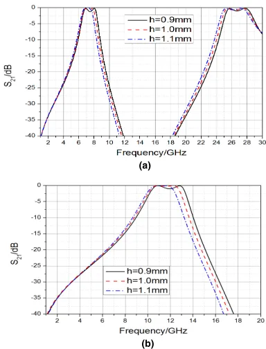
First, for the PSS proposed in Fig.4, the relative dielectric constant of the fixed coupling dielectric is 2.65, changing only the thickness of the two layers of dielectric. Set h to 0.9mm, 1mm and 1.1mm respectively, other structural parameters remain unchanged. The influence of dielectric thickness on PSS transmission characteristics was studied, the simulation results are shown in Fig.9.Secondly, the fixed coupling dielectric thickness h is 1 mm, the relative dielectric constants are set to 2.2, 2.65, and 3.2 respectively, other struc-tural parameters remain unchanged. The influence of relative dielectric constantεr on PSS transmission characteristics is
studied. the simulation results are shown in Fig.10.
[image:7.576.318.510.64.316.2]As can be seen from Fig.9, with the increase of the dielec-tric thickness h, the coupling effect between the layers will be weakened. First, the most prominent feature is that with the increase of h, the in-band insertion loss at the peak fre-quency point decreases. Secondly, with the increase of h, each passband becomes more flat. Finally, from Fig.9(a), for TE
FIGURE 9. Transmission curve of PSS at different dielectric thicknesses when normal incidence.
wave incidence, the TE low-frequency passband bandwidth decreases with the increase of h, and the TE high-frequency passband bandwidth increases with the increase of h. From Fig.9(b), for TM wave incidence, the TM passband band-width decreases with the increase of h. And the resonant frequencies of the three passbands all slightly shift to low frequencies with the increase of h.
According to Munk’s design theory, the resonant frequency
f =f0/ √
(1+εr)/2 in the medium, wheref0is the resonant
frequency in vacuum. From Figs.10(a) and 10(b), it can be seen that the other parameters of PSS are kept unchanged whether the incident TE wave or TM wave, and when the relative dielectric constant εr increases from 2.2 to 3.2,
the resonant frequency moves to the low frequency, fully conforming to munk’s theory. Considering the transmission of low frequency band signals, it can be processed on a dielectric substrate with a relatively high dielectric constant and a relatively thin thickness, which can be directly pasted like wallpaper and is convenient for application.
C. INFLUENCE OF SIZE CHANGE OF ASYMMETRIC JERUSALEM CROSS AND INTERMEDIATE METAL LAYER ON PSS TRANSMISSION CHARACTERISTIC
FIGURE 10. Influence of PSS transmission characteristics under different relative dielectric constants at normal incidence.
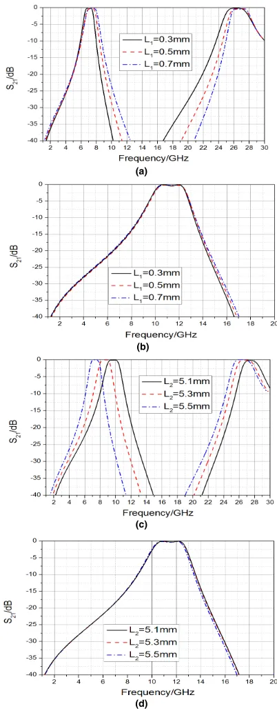
According to the simulation of the model shown in Fig.4, we change the sizes L1 and L2 of asymmetric Jerusalem
cross long arms, and the influence of L1and L2of different
sizes on PSS transmission performance when electromag-netic waves are incident normally is shown in Fig.11. As can be seen from Fig.11(a), with the increase of L1, the falling
edge on the right side of TE low frequency passband moves toward the direction of high frequency, and the bandwidth increases. The falling edge on the left side of the TE high-frequency passband also moves toward the high-high-frequency direction, reducing the bandwidth. The center frequencies of both passbands are slightly shifted to high frequencies as L1
increases. As can be seen from Fig.11(c), with the increase of L2, the two passbands of TE polarization move toward
the low frequency direction as a whole, and the bandwidth hardly changes, so the value of L2only determines the
posi-tion of TE passband. As can be seen from Fig.11(b) and Fig.11(d), the width and position of the TM passband are almost unchanged no matter how L1 and L2 change. This
further shows that the asymmetric Jerusalem cross long arm plays a key role in the selective transmission of TE polarized waves.
Similarly, according to the simulation of the model shown in Fig.4, we change the sizes L3 and L4 of asymmetric
Jerusalem cross short arms, and the influence of L3and L4
of different sizes on PSS transmission performance when electromagnetic waves are incident normally is shown in Fig.12. As can be seen from Fig.12(b), with the increase of L3, the TM passband moves toward the low frequency
direction as a whole, and the bandwidth hardly changes. Therefore, the value of L3 only determines the position of
FIGURE 11. Influence of L1and L2of different sizes on PSS transmission performance when electromagnetic waves are incident normally.
the TM passband. As can be seen from Fig.12(d), with the increase of L4, the falling edge on the right side of TM
pass-band moves toward the high frequency direction, the pass- band-width increases, and the center frequency slightly moves toward the high frequency. As can be seen from Fig.12(a) and Fig.12(c), the width and position of the TE passband are almost unchanged no matter how L3 and L4 change. This
[image:8.576.315.516.64.581.2]FIGURE 12. Influence of L3and L4of different sizes on PSS transmission performance when electromagnetic waves are incident normally.
plays a key role in the selective transmission of TM polarized waves.
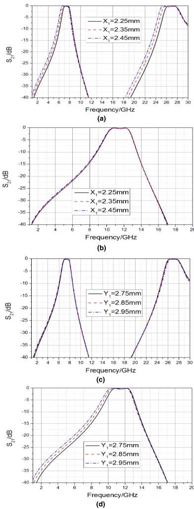
According to the simulation of the model shown in Fig.4, we change that aperture size X1and Y1of the intermediate
metal layer, and the influence of X1 and Y1 of different
sizes on PSS transmission performance when electromag-netic waves are incident normally is shown in Fig.13.As can be seen from Figs.13(a) and 13(b), with the increase of X1,
the left falling edge of TE passband moves toward the low frequency direction, and the passband bandwidth increases.
FIGURE 13. Influence of X1and Y1of different sizes on PSS transmission performance when electromagnetic waves are incident normally.
No matter how X1 changes, the TM passband width and
position are almost unchanged. Similarly, as can be seen from Figs.13(c) and 13(d), with the increase of Y1, the left
falling edge of TM passband moves toward the low frequency direction, and the passband bandwidth increases. No matter how Y1 changes, the TE passband width and position are
almost unchanged.
[image:9.576.315.511.64.578.2]independently controlled by the size change of a cer-tain parameter in the asymmetric Jerusalem cross struc-ture and the intermediate metal layer. Therefore, based on the independent controllability of parameters, TE pass-band and TM passpass-band can be independently adjusted within a certain range according to actual application requirements.
D. INFLUENCE OF THE PROPOSED PSS’S OVERALL
ROTATION OF 90◦ON ITS TRANSMISSION
CHARACTERISTIC
[image:10.576.297.537.426.546.2]When TE and TM waves are incident normally, if PSS struc-ture is rotated 90◦ , its polarization selection state can be switched. The CST microwave studio electromagnetic sim-ulation software was used for simsim-ulation calcsim-ulation, and the results are shown in Fig.14. Among them, Fig.14(a) shows a comparison curve of the transmission characteristics of TE waves before and after rotation, and Fig.14(b) shows a comparison curve of the transmission characteristics of TM waves before and after rotation. As can be seen from Fig.14, the original TE bandpass is converted into a TM bandpass and the original TE bandstop is converted into a TM bandstop, that is, the proposed PSS has good reconfigurable charac-teristics. Similarly, after the PSS structure is rotated 90◦, the electromagnetic wave still has good angle stability and polarization selection characteristics in the incident range of 0◦-60◦.Therefore, the reconfigurable characteristic of PSS provides a new design idea for the design of polarization wave generator and polarization separation structure.
FIGURE 14. Comparison curves of transmission characteristics of polarized waves in different modes before and after rotation. (a) TE mode. (b) TM mode.
IV. EXPERIMENTAL RESULTS
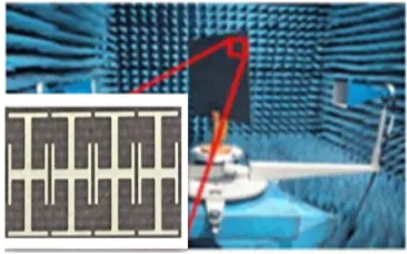
[image:10.576.54.255.439.695.2]In order to verify the performance of the proposed second-order multi-band PSS, a sample was fabricated using printed circuit board (PCB) technology, as shown in Fig.15. Fig.15(a) shows the asymmetric Jerusalem cross structure of the top and bottom layers of the processed sample.Fig.15(b) shows the square ring aperture structure of the intermediate metal layer of the processed sample. The dielectric substrate parameters of the machined sample are the same as the simulation param-eters. The top metal structure was etched on one surface of one dielectric substrate, and the middle and bottom structures were patterned on both sides of the other dielectric substrate. Then the two substrates are glued together. The processed sample plate has an overall structure size of 497.25×500mm2 and contains 153×80 elements. The performance of the sam-ple was measured by free-space test method. In a microwave anechoic chamber, two double-ridge horn antennas were con-nected to the receiving and transmitting terminals of the vector network analyzer (VNA), as shown in Fig.16, to be measured by this system. The measuring frequency range is 1-30GHz, and the incidence electromagnetic wave is TE polarized wave and TM polarized wave, and the incidence angles are 0◦, 30◦and 60◦ respectively. The distance from the PSS sample to the transmitting antenna is set to 1.4m, and the distance from the PSS sample to the receiving antenna is also set to 1.4m.This arrangement ensures that quasi-plane waves are incident on PSS samples and can effectively receive electromagnetic waves at the receiving end. In order to reduce
FIGURE 15. Fabricated prototype of the PSS. (a) Top and bottom asymmetric Jerusalem cross structure. (b) Square ring aperture structure of intermediate metal layer.
[image:10.576.325.508.600.714.2]the interference of the external environment and the influence of system errors on the measurement, a normalization method is adopted in the measurement process so as to ensure the accuracy of the measurement as much as possible.
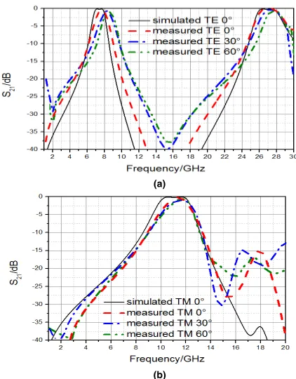
FIGURE 17. Simulation and measurement of TE and TM polarization at different incidence angles transmission curve. (a) TE polarization. (b) TM polarization.
The measured results of PSS samples are shown in Fig.17. Fig.17(a) and Fig.17(b) show the comparison of the measurement results and simulation results of the transmis-sion characteristics of TE and TM polarized waves at dif-ferent incident angles, respectively. It can be seen from the figure that when TE and TM waves are incident at 0◦, 30◦
and 60◦ respectively, the measured transmission results are basically consistent with the simulated transmission results, except that the measured curve slightly deviates from the sim-ulated curve. There are three main reasons for the above dif-ference between simulation and measurement:(1) The error between the dielectric constant of the actual sample dielectric substrate and the simulation parameters. (2) Error between actual thickness of sample dielectric substrate and simula-tion parameters. (3) Artificial or systematic error. The mea-surement results show that the proposed PSS structure has good polarization selection characteristics and angle stability, which provides a new design idea for designing a polarization wave generator or polarization separation structure on a lim-ited space satellite(or multipath) communication system.
V. CONCLUSION
In this paper, based on the sub-wavelength periodic array structure and the coupling resonance filtering mechanism,
a low profile second-ordermulti-band PSS structure com-posed of three layers of metal structure and two layers of dielectric substrate is designed in this paper. When TE and TM polarized waves are incident normally, the TE polarized second-order passband is generated in the 6.50GHz-8.07GHz band and 25.42GHz-28.46GHz frequency band, and the TM polarized second-order passband is generated in the 9.90GHz-12.88GHz frequency band. The proposed PSS structure has significant miniaturization characteristics. Sim-ulation and experimental results show that: The proposed PSS structure has good polarization selection characteristics and out-of-band suppression level, and has excellent angular stability in the 0◦−60◦scanning range. Due to the indepen-dent control characteristics of asymmetric Jerusalem cross structure parameters and intermediate metal layer param-eters, TE polarized second-order passband and TM polar-ized second-order passband can be independently adjusted according to actual application requirements within a cer-tain range, making the design more flexible. By rotating the PSS structure by 90◦, the polarization filtering state can be switched. That is, the original TE band pass is changed into TM band pass, and the original TE band stop is changed into TM band stop. It provides a new design idea for the design of polarization wave generator and polarization separation structure on a limited space satellite(or multipath) commu-nication system.
REFERENCES
[1] B. A. Munk,Frequency Selective Surfaces: Theory and Design. New York, NY, USA: Wiley, 2000.
[2] T. K. Wu, Ed.,Frequency Selective Surface and Grid Array. New York, NY, USA: Wiley, 1995.
[3] A. Ferraro, D. C. Zografopoulos, R. Caputo, and R. Beccherelli, ‘‘Peri-odical elements as low-cost building blocks for tunable terahertz filters,’’
IEEE Photon. Technol. Lett., vol. 28, no. 21, pp. 2459–2462, Nov. 1, 2016. [4] V. Sanphuang, N. Ghalichechian, N. K. Nahar, and J. L. Volakis, ‘‘Recon-figurable THz filters using phase-change material and integrated heater,’’
IEEE Trans. THz Sci. Technol., vol. 6, no. 4, pp. 583–591, Jul. 2016. [5] Q. Chen and Y. Fu, ‘‘A planar stealthy antenna radome using absorptive
frequency selective surface,’’Microw. Opt. Technol. Lett., vol. 56, no. 8, pp. 1788–1792, Aug. 2014.
[6] Q. Chen, L. Liu, L. Chen, J. Bai, and Y. Fu, ‘‘Absorptive frequency selective surface using parallel LC resonance,’’Electron. Lett., vol. 52, no. 6, pp. 418–419, 2016.
[7] Q. Chen, J. J. Bai, L. Chen, and Y. Q. Fu, ‘‘A miniaturized absorptive fre-quency selective surface,’’IEEE Antennas Wireless Propag. Lett., vol. 14, pp. 80–83, 2015.
[8] B. Lin, J.-L. Wu, X.-Y. Da, W. Li, and J.-J. Ma, ‘‘A linear-to-circular polar-ization converter based on a second-order band-pass frequency selective surface,’’Appl. Phys. A, Solids Surf., vol. 123, p. 43, Jan. 2017. [9] D. Wang, W. Che, Y. Chang, K.-S. Chin, and Y. L. Chow,
‘‘Combined-element frequency selective surfaces with multiple transmission poles and zeros,’’IET Microw., Antennas Propag., vol. 8, no. 3, pp. 186–193, Feb. 2014.
[10] Y. Rahmat-Samii and A. C. Densmore, ‘‘Technology trends and challenges of antennas for satellite communication systems,’’IEEE Trans. Antennas Propag., vol. 63, no. 4, pp. 1191–1204, Apr. 2015.
[11] M. R. Chaharmir and J. Shaker, ‘‘Design of a multilayer X-/Ka-band frequency-selective surface-backed reflectarray for satellite applica-tions,’’IEEE Trans. Antennas Propag., vol. 63, no. 4, pp. 1255–1262, Apr. 2015.
[13] J. D. Ortiz, J. D. Baena, V. Losada, F. Medina, R. Marqués, and J. L. A. Quijano, ‘‘Self-complementary metasurface for designing narrow band pass/stop filters,’’IEEE Microw. Wireless Compon. Lett., vol. 23, no. 6, pp. 291–293, Jun. 2013.
[14] M.-A. Joyal and J.-J. Laurin, ‘‘A cascaded circular-polarization-selective surface at K band,’’ inProc. IEEE Int. Symp. Antennas Propag., Jul. 2011, pp. 2657–2660.
[15] J. Jian, G. Jin-Song, X. Nian-Xi, and C. Xin, ‘‘Design and study of the polarization selective surface based on the complementary screens,’’Acta Phys. Sinica, vol. 62, no. 19, p. 197303, 2013.
[16] W. Xiu-Zhi, G. Jin-Song, and X. Nian-Xi, ‘‘Characteristics of polarization separation of frequency selective surface by lumped inductors and capaci-tors,’’Acta Phys. Sinica, vol. 62, no. 14, p. 147307, 2013.
[17] W. Xianget al., ‘‘Design of metamaterial frequency selective surface with polarization selectivity,’’Acta Phys. Sinica, vol. 60, no. 11, p. 114201, 2011.
[18] R. Pous and D. M. Pozar, ‘‘Frequency-selective surface using aperture-coupled microstrip patches,’’Electron. Lett., vol. 25, no. 17, pp. 1136–1138, Aug. 1989.
[19] G. Q. Luo, Z. F. Hu, L. X. Dong, and L. L. Sun, ‘‘Planar slot antenna backed by substrate integrated waveguide cavity,’’IEEE Antennas Wireless Propag. Lett., vol. 7, pp. 236–239, 2008.
[20] G. Q. Luoet al., ‘‘Filtenna consisting of horn antenna and substrate integrated waveguide cavity FSS,’’IEEE Trans. Antennas Propag., vol. 55, no. 1, pp. 92–98, Jan. 2007.
[21] G. Q. Luo, Z. F. Hu, Y. Liang, L. Y. Yu, and L. L. Sun, ‘‘Development of low profile cavity backed crossed slot antennas for planar integration,’’
IEEE Trans. Antennas Propag., vol. 57, no. 10, pp. 2972–2979, Oct. 2009. [22] G. Q. Luo, W. Hong, H. J. Tang, J. X. Chen, and K. Wu, ‘‘Dualband frequency-selective surfaces using substrate-integrated waveguide tech-nology,’’IET Microw., Antennas Propag., vol. 1, no. 2, pp. 408–413, Apr. 2007.
[23] K. Sarabandi and N. Behdad, ‘‘A frequency selective surface with miniaturized elements,’’IEEE Trans. Antennas Propag., vol. 55, no. 5, pp. 1239–1245, May 2007.
[24] F. Bayatpur and K. Sarabandi, ‘‘Multipole spatial filters using metamaterial-based miniaturized-element frequency-selective surfaces,’’
IEEE Trans. Microw. Theory Techn., vol. 56, no. 12, pp. 2742–2747, Dec. 2008.
[25] F. Bayatpur and K. Sarabandi, ‘‘Tuning performance of metamaterial-based frequency selective surfaces,’’ IEEE Trans. Antennas Propag., vol. 57, no. 2, pp. 590–592, Feb. 2009.
[26] F. Bayatpur and K. Sarabandi, ‘‘Miniaturized FSS and patch antenna array coupling for angle-independent, high-order spatial filtering,’’IEEE Microw. Wireless Compon. Lett., vol. 20, no. 2, pp. 79–81, Feb. 2010. [27] F. Bayatpur and K. Sarabandi, ‘‘Design and analysis of a tunable
miniaturized-element frequency-selective surface without bias network,’’
IEEE Trans. Antennas Propag., vol. 58, no. 4, pp. 1214–1219, Apr. 2010. [28] M. Moallem and K. Sarabandi, ‘‘Miniaturized-element frequency selective surfaces for millimeter-wave to terahertz applications,’’IEEE Trans. THz Sci. Technol., vol. 2, no. 3, pp. 333–339, May 2012.
[29] F. Bayatpur and K. Sarabandi, ‘‘Single-layer high-order miniaturized-element frequency-selective surfaces,’’IEEE Trans. Antennas Propag., vol. 56, no. 4, pp. 774–781, Apr. 2008.
[30] M. Li and N. Behdad, ‘‘A third-order bandpass frequency selective surface with a tunable transmission null,’’IEEE Trans. Antennas Propag., vol. 60, no. 4, pp. 2109–2113, Apr. 2012.
[31] S. M. A. M. H. Abadi, M. Li, and N. Behdad, ‘‘Harmonic-suppressed miniaturized-element frequency selective surfaces with higher order bandpass responses,’’ IEEE Trans. Antennas Propag., vol. 62, no. 5, pp. 2562–2571, May 2014.
[32] N. Behdad, M. Al-Joumayly, and M. Salehi, ‘‘A low-profile third-order bandpass frequency selective surface,’’IEEE Trans. Antennas Propag., vol. 57, no. 2, pp. 460–466, 2009.
[33] M. A. Al-Joumayly and N. Behdad, ‘‘A generalized method for synthesiz-ing miniaturized element band-pass frequency selective surfaces,’’ inProc. IEEE Antennas Propag. Soc. Int. Symp., Toronto, ON, Canada, Jul. 2010, pp. 1–4.
[34] G. Bharti, K. R. Jha, G. Singh, and R. Jyoti, ‘‘Design of dual-polarized and angular stable new bandpass frequency selective surface in X-band,’’
Telecommun. Syst., vol. 61, no. 3, pp. 559–567, 2016.
[35] M. Al-Joumayly and N. Behdad, ‘‘A new technique for design of low-profile, second-order, bandpass frequency selective surfaces,’’IEEE Trans. Antennas Propag., vol. 57, no. 2, pp. 452–459, Feb. 2009.
[36] O. Manoochehri, S. Abbasiniazare, A. Torabi, and K. Forooraghi, ‘‘A second-order BPF using a miniaturized-element frequency selective surface,’’Prog. Electromagn. Res. C, vol. 31, pp. 229–240, 2012. [37] O. Luukkonen, F. Costa, C. R. Simovski, A. Monorchio, and
S. A. Tretyakov, ‘‘A thin electromagnetic absorber for wide incidence angles and both polarizations,’’IEEE Trans. Antennas Propag., vol. 57, no. 10, pp. 3119–3125, Oct. 2009.
[38] W. Cong-Yi, X. Cheng, and W. Rui-Xin, ‘‘Wideband and large inci-dent angle wave transparent material based on frequency selective sur-face with miniaturized elements,’’Acta Phys. Sinica, vol. 63, no. 13, pp. 137803-1–137803-5, 2014.
HUI WANGreceived the B.S. and M.S. degrees in communication engineering from Xidian Uni-versity, Xi’an, Shaanxi, China, in 2008 and 2013, respectively. He is currently pursuing the Ph.D. degree in electronic science and technology with Air Force Engineering University, Xi’an. He con-ducted research under the guidance of Prof. S. Qu. His research interests include frequency selective surface and radome.
LIN ZHENGwas born in 1986. He received the Ph.D. degree in electronics science and technol-ogy from Air Force Engineering University, Xi’an, Shaanxi, China, in 2015. He is currently with the Department of Basic Sciences, Chinese Air Force Engineering University. His research inter-ests include frequency selective surface, metama-terial, and radome.
MINGBAO YAN received the B.S. and M.S. degrees in physics from Qufu Normal Univer-sity, Qufu, China, in 2005 and 2008, respectively, and the Ph.D. degree in physical electronics from Air Force Engineering University, Xi’an, Shaanxi, China, in 2016. Since 2008, he has been with Air Force Engineering University, where he is currently an Associate Professor of physical elec-tronics. His current research interests include fre-quency selective surface and the design of stealth radome metamaterial.
SHAOBO QUreceived the B.S. degree in physics from the Fuyang Normal College, Fuyang, Anhui, China, in 1984, the M.S. degree in physics from Sichuan Normal University, Chengdu, China, in 1991, and the Ph.D. degree in materials sci-ence and engineering from Northwest Polytech-nical University, Xi’an, China, in 2001. Since 2001, he has been with the Department of Applied Mathematics and Physics, Air Force Engineering University, Xi’an, where he is currently a Professor in physical electronics. His research interests include materials physics, metamaterials, and electronic materials and devices.