COMPUTATIONAL ELECTROMAGNETICS:
THE PAST, THE PRESENT AND THE FUTURE
Jan K. Sykulski
Electrical Power Engineering, School of Electronics and Computer Science University of Southampton, Southampton, UK, [email protected]
Abstract
The paper provides an overview of the state of the art in Computational Electromagnetics (CEM). Examples are given with a focus on applications related to electrical engineering. Design and optimisation, as well as development of new materials, are emphasised as of paramount importance in the real engineering world. Modern computational methods based on finite elements and related techniques have now become a mature design tool, but the complexity of the underlying mathematics and physics often hampers widespread use of these efficient techniques. Recent advances in general purpose software are encouraging but much remains to be done in improving the standards of education to remove the mist of mystery surrounding the subject.
1. INTRODUCTION
The research activity known as Computational Electromagnetics (CEM) has evolved alongside the modern developments in the digital computing hardware. Moreover, CEM is both a special case and part of the broader subject of computational mechanics. The speciality arises in many obvious ways, e.g. free space is an unbounded magnetic ‘material’, there is a vast range of physical dimensions encountered with critical feature sizes often varying over many orders of magnitude, the fundamental properties of Maxwell’s equations are different to equations governing other physical phenomena. There is also a very broad spectrum of frequencies encountered: from DC to daylight. Activities of the CEM community are well organised within the International Compumag Society [1,2], an independent international organisation in existence since 1993 with nearly 700 members from over 40 countries. The IEE Professional Network on Electromagnetics [3] is also gaining momentum and establishing itself as an international forum for discussion. The IEEE Magnetics Society [4] and ACES [5] manage the activities in North America. Journals such as IEE Proceedings [6], IEEE Transactions on Magnetics [7] and COMPEL [8] contain a significant number of papers showing fundamental advances and applications of CEM. There are many conferences reporting regularly on recent developments, including COMPUMAG [9,10], CEFC [11], CEM [12,13], ISEF [14], EPNC [46], ISTET [47] and ISEM [48].
2. COMPUTER AIDED DESIGN
[image:2.612.72.305.289.459.2]Recent advances in CEM, encouraged by continuing increase of power and speed of computers, make finite element and related modelling techniques an attractive alternative to well established semi-analytical and empirical design methods, as well as to the still popular ‘trial and error’ approach. Figure 1 shows a typical system incorporating FE computation [15,16]. First, a designer builds a computational model of his physical problem; this is a vital step, often underestimated, which may decide on success or failure of the whole process. Clearly, the model must be adequate for the results to be meaningful – this emphasises the significance of human input and importance of an experiment or alternative models for validation purposes. The CAD system facilitates finding a solution to the modelled problem.
Fig. 1 A typical CAD system for electromagnetics
Fig. 2 A general DEM and its relation to FE package
Parameterisation of the model is often desired, so that various parts – as well as the whole device – may be constrained in a convenient way, for example for optimisation or sensitivity analysis. A typical example of software development addressing this issue is the concept of Design Environment (DEM) [23,26,27] – see Fig. 2. A DEM facilitates the use of electromagnetic analysis software by providing an application specific shell to guide a non-specialist through the geometric design and physical property specification of a class of device. DEMs are created by experts and contain a parameterised model of a device with a set of decision making routines suggesting optimal representation of materials and boundary conditions, followed by automatic analysis of performance. The post-processor offers top-level commands for specific tasks such as calculation of device parameters.
One of the more important issues associated generally with such CAD systems is the question of error estimation and the ability of the system to refine the model to improve the accuracy. Various adaptive schemes are available based on h, p or r mesh refinement [16] or dynamic bubbles shown in Fig. 3. Model
From design
CAD Geometrical data
Material properties Excitation sources
Boundary conditions Data files Preprocessor
Mesh
Designer Interface
Solver
Solution of equations
Result files Field plots, forces,
stored energy, losses, computational errors, et Postprocessor
c
Solution
[image:2.612.352.535.362.521.2]Back to design
Fig. 3 Anisotropic mesh using dynamic bubbles [28]
PC-OPERA
Pre and Post-Processor 7.024 01/Feb/1999 18:40:47 Page 5
UNITS
Length : mm
Flux density : T Field strength : A m-1
Potential : Wb m-1
Conductivity : S m-1
Source density: A m-2
Power : W
Force : N
Energy : J
Mass : kg
PROBLEM DATA lvdt1e5_ref3.ac Linear elements Axi-symmetry Modified R*vec pot. Magnetic fields AC solution Frequency = 100000.0
6736 elements 3394 nodes
5 regions
0.0 1.0 2.0 3.0 4.0 5.0 6.0 7.0 8.0 9.0 10.0 2.0
3.0 4.0 5.0 6.0 7.0 8.0 9.0
R [mm] Z [mm]
1
2 3
[image:2.612.57.309.502.682.2]4
Fig. 4 3D model of an induction motor DEM Data Files
Existing FE Software Package
Pre- Processor
Analysis Module
Model Generation
Module
Check
Routine DimensioningProcedure
Design Parameter Calculation Procedure
Post-
Processor End
[image:2.612.331.538.548.685.2]The CEM community has gone a long way to address the needs of designers and contemporary commercial software is capable of solving static, quasi-static and full transient problems in 2D as well as in 3D. Nonlinearity of materials, permanent magnets, various shapes of excitation coils – these are just examples of what can easily be solved (see an example of Fig. 4). Finally, coupled problems can be handled involving interactions between electromagnetic field, motion and supplying circuit [29].
3. FORMULATIONS AND TECHNIQUES
There has been important progress in fundamental formulations providing more solid foundations for numerical field analysis. These have been reported at COMPUMAG [9], CEFC [11] and CEM [12]. Lack of space does not permit to elaborate on these developments here but some more exciting advances are mentioned. Equally, progress has been made in implementation of new techniques leading to more efficient, faster, more accurate and numerically stable algorithms. The following is a non-exhaustive list of such advances which have recently made the greatest impact on the CEM community.
• a new Finite Element Difference (FED) method, • higher order Finite Difference Time Domain
(FDTD) approach,
• further developments of the Transmission Line Matrix (TLM) method,
• advances of the Multiple Multipole Technique (MMT),
• the use of Finite Integration Technique (FIT),
• a new Subspace Projection Extrapolation (SPE) scheme,
• working field theory problems with Random Walks, • formulations in terms of differential geometry, • the usage of total/reduced magnetic vector potential
and electric scalar potential,
• an introduction of Lie derivative as a tool for force computation,
• implementation of edge and facet elements, • improved anisotropy models,
• efficient application of Continuum Design Sensitivity Analysis (CDSA).
4. MODELLING OF NEW MATERIALS
Discovery and/or development of new materials present a modelling challenge and often lead to reformulation of fundamental equations or methods of solution. We will
focus here on recent advances in superconductivity. Ceramic superconducting materials were discovered in 1986 and their main advantage is that they can operate at liquid nitrogen temperature (78K) – hence the name High Temperature Superconductors (HTS) – and thus offer cheap and reliable technology (often compared to water cooling). With practical current densities 20 to 40 times larger than in conventional copper windings they have great potential in electric power applications (generators, motors, fault current limiters, transformers, flywheels, cables, etc.), as losses are significantly reduced and power output per volume increased. From the design point of view they offer a challenge because of very highly non-linear characteristics and anisotropic properties of materials, and due to unconventional design solutions. Fundamental characteristics and underlying physical processes are well described in literature. Some recent advances at Southampton University in the application of the HTS technology to electric power devices are described in [30-39].
There is continuing significant activity around the world in the development of HTS tapes and wires, applications of the technology to power devices and modelling of fundamental processes in the superconducting materials. From the practical point of view the ability to predict and reduce all ‘cold’ losses is of paramount importance to demonstrate economic advantages of HTS designs. The behaviour and characteristics of the highly non-linear and anisotropic HTS materials is markedly different to conventional conductors. A typical field distribution is depicted in Fig. 5, whereas the dependence of AC losses on field level is shown if Fig 6 [33]. It can be clearly seen that field direction is of paramount importance and thus steps need to be taken to ‘shape’ the leakage field in the device to avoid excessive losses and prevent the conductor from being exposed to fields higher than critical.
0 1 2 3 4 5 6 7 8 9 10 11
0 10 20 30 40 50 6
Secondary Current (A)
Los
s (
W
)
Measured (no Flux Diverters)
Calculated (no Flux Diverters)
Calculated (with Flux Diverters)
Measured (with Flux Diverters)
[image:4.612.61.287.78.258.2]0
Fig. 6 AC loss as a function of peak magnetic field
[image:4.612.312.538.89.389.2]Low Temperature Superconductivity has not been very successful in electric power applications due to low reliability, high cost and difficult technology. HTS offer better thermal stability, cheaper cooling and improved reliability. Currently all conceptual HTS designs and small demonstrators use BSCCO tapes at temperatures between 20K and 30K because critical fields and currents are an order of magnitude better than at 78K and it is possible to have a core-less design. However, liquid neon or helium gas is needed leading to increased cost and complexity of refrigeration plant, reduced thermodynamic efficiency (by about eight times) and worse reliability and higher maintenance requirements. All Southampton designs use cooling at 78/81/65/57 K (liquid nitrogen or air / sub-cooled nitrogen or air).
Fig. 7 HTS winding in a 10kVA transformer
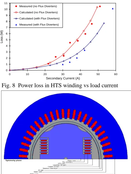
[image:4.612.316.539.418.587.2]The first devise built and successfully tested in Southampton in 1998 was a small 10kVA demonstrator transformer (Fig. 7) [39]. A particularly satisfying result was the two-fold reduction of losses through introduction of magnetic flux diverters as demonstrated by Fig. 8. These diverters reduce an unwanted component of magnetic field in the coil region.
Fig. 8 Power loss in HTS winding vs load current
Fig. 9 A cross-section through 100kVA HTS generator
Fig. 10 3D flux density and its distribution
[image:4.612.71.299.462.589.2]full-load losses that include the effects of the MMF harmonics of the stator winding. Two models were used: full transient non-linear rotating (no-load, see Fig 10), and a combination of static and steady-state (full-load), respectively. Losses are released into liquid nitrogen and have to be removed using inefficient refrigeration system. Each 1W of loss requires between 15 – 25 W of installed refrigeration power at 78K (a similar figure at 4K would be about 1000 W).
5. OPTIMISATION
Optimal design of electromechanical devices often necessitates repetitive usage of finite-element (FE) solvers, or other numerically intensive field computation. A direct way of incorporating field modelling into an optimisation loop is to call the FE package every time a function evaluation is needed. Although fairly straightforward in implementation, this on-line approach will normally lead to unacceptable computing times, as for each set of selected design parameters a full field analysis needs to be undertaken. The number of necessary calls to the FE software escalates as the number of design variables increases; moreover, additional calls are normally required to calculate each gradient of the objective function. Although theoretically this is of no consequence, in the design office environment such an approach becomes impractical.
The Minimum Function Calls (MFC) approach relies on evaluating the objective function a priori for a number of pre-determined cases and fitting an interpolating function through the data points [40]. The optimiser then uses the interpolating function rather than calling the FE directly. In this Response Surface Methodology (RSM) approach it is usual to use polynomial interpolating functions. Using the RSM reduces computing times dramatically, but care must be taken not to sacrifice accuracy. Extensive numerical experiments have shown that further significant improvements may be achieved by introducing on-line learning with dynamic weighting [40]. To illustrate the process a brushless permanent magnet (PM) motor has been optimised for efficiency (with minimum torque constraint) in terms of magnet height, tooth width and stack length. The convergence is illustrated in Fig. 11.
The deterministic approach, despite the addition of learning points, may not be able to avoid local minima traps. If this is identified as a potential problem stochastic techniques may offer a better choice. Most such techniques are very expensive in terms of number of necessary function evaluations and thus impractical.
Some more recent methods, however, look more promising and one such technique introduced originally in [41] is reported here. It uses a combination of Evolution Strategy, Differential Evolution and Multiquadrics Interpolation (ES/DE/MQ) as shown in Fig. 12. This hybrid method has been shown to be able to avoid local minima traps for a number of test functions and achieves a significant reduction of the number of necessary function calls, making the approach suitable for computationally intensive FE design/optimisation problems. Moreover, the quality of the resultant optimum is comparable to, or better than, those obtained using other methods.
60 65 70 75 80 85 90 95
0 10 20 30 40 50 60
No. of Runs
Efficiency (%)
0.50 1.00 1.50 2.00 2.50 3.00
Torque [N-m]
Efficiency
Torque
Torque (min)
[image:5.612.313.549.239.383.2]First 20 points required for curve fitting before starting optimisation
[image:5.612.314.520.418.582.2]Fig. 11 Convergence of efficiency and torque
Fig. 12 Flowchart of the ES/DE/MQ method [41]
which provides an approximation of real function. The notion of Membership Functions (MFs) is introduced which can be described by Gaussian, generalised bell or other curves. During the supervised training process the parameters of each MF are modified using the back-propagation algorithm and the consequent parameters established using least squares, ultimately providing an approximation of the system under investigation. This empirical model effectively replaces the actual function generator – in this case the finite element solver – easing the computational cost when applying the optimisation routine. This comprises a GA to identify the locality of the global optimum followed by the SQP method to isolate it accurately. The latter is possible due to the extraction of derivative information from the neuro-fuzzy model.
There is growing interest in the ways in which the performance of a specific device could be modelled using a neural network. Such a network learns the shape of the hyper-surface and provides a fast evaluation of any point in it. Typically, the neural network is trained in a batch mode, prior to the optimisation process – essentially “off-line”. A recent attempt has been made to construct a system which can provide “on-line” training, i.e. a network which is capable of learning and modifying its behaviour as it is used [43]. Such a network has major benefits over a static system in that it can handle a large number of variations of a device and track developments in design related to material changes and manufacturing processes.
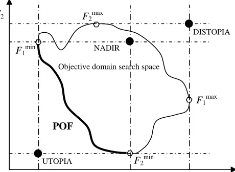
Design has to be put in the context of general trends in optimisation methods The role of multi-objective tasks is increasing as practical designs often involve conflicting requirements. Such problems may be converted into single-objective tasks with a priori application of knowledge or imposition of a decision (e.g. weighting factors), but it is argued that information can easily be lost in the process. Instead the application of Pareto Optimal Front (POF) approximation is advocated. The mathematical theory of Pareto optimisation may be somewhat complicated [44], but some basic definitions and properties are easily explained using a special case of two objective functions being minimised as shown in Fig. 13.
[image:6.612.312.542.90.258.2]Finally, often in practice, it is the improvement to the design, not necessarily a global optimum, which is of interest. Hence the sensitivity analysis is of great value as computing times are not affected by the number of design variables. The Continuum Design Sensitivity Analysis (CDSA) is particularly to be recommended as standard EM software may be used for extracting gradient information [45].
Fig. 13 Example showing Pareto Optimal Front and UTOPIA, DISTOPIA and NADIR points
6. INDUSTRIAL REQUIREMENTS
From the industrial perspective it is probably true to say that many managers still perceive computational electromagnetics as a kind of “black magic” – and yet these are the very people who would benefit most from using CEM techniques to reduce design times and costs. There is lack of appropriate skills to benefit fully from the enormous power and versatility of the available CEM tools. It may be argued that three categories of users are required in industry:
• those able to run EM software with basic understanding of field displays and ability to interpret the numerical results to incorporate them into design processes;
• design experts who understand the language of electromagnetics and are capable of creating computational models using available software;
• EM software developers – the ultimate CEM experts producing computational tool.
Decision makers in industry – in their very best interest – need to support the universities and government in providing sufficient funding for both the development of CEM tools and for providing sufficient education at different levels. Academic institutions face a great opportunity of reversing the current trend of reducing the amount of EM teaching and making sure that relevant courses are available to undergraduates and engineers in industry. There is some cause for optimism as progress with CEM software development is accelerating and more programs find their way to design offices as an every day tool.
POF
Objective domain search space
F2 F2max
DISTOPIA
NADIR
F1min
F1max
F2min
6. FUTURE DEVELOPMENTS
Further progress is required and a possible list of topics for research and development may include:
• adaptive meshing with particular emphasis on problems with strong skin effect,
• reliable error estimation (a posteriori and a priori), • code development for high speed computing,
• efficient handling of non-linearity, hysterisis and anisotropy,
• modelling of new types of materials (e.g. composite, superconducting),
• incorporation of linear movement and rotation of some parts of the device,
• combined modelling of fields and circuits (e.g. supply electronic circuits),
• coupled problems (electromagnetic + stress + temperature, etc),
• optimisation (deterministic and stochastic, practical implications),
• integrated design systems (combined mechanical, electromagnetic, thermal, economic).
It can be argued, however, that CAD in Magnetics is already a mature practical tool for design and optimisation of a variety of electromechanical devices and the engineering community can benefit from tremendous advances that occurred in the field over the past many years.
7. REFERENCES
[1] International Compumag Society,
http://www.compumag.co.uk/
[2] Sykulski J.K. (editor), International Compumag
Society Newsletter, ISSN 1026-0854
[3] Professional Network Electromagnetics, IEE,
http://www.iee.org/OnComms/pn/electromagnetics/
[4] Magnetics Societyhttp://www.ieeemagnetics.org/
[5] ACEShttp://aces.ee.olemiss.edu/
[6] IEE Proceedings
http://www.iee.org/Publish/Journals/ProfJourn/Proc/
[7] IEEE Transactions on Magnetics
http://www.ieeemagnetics.org/, ISSN 0018 9464
[8] COMPEL, ISSN 0332 1649
http://www.emeraldinsight.com/compel.htm,
[9] COMPUMAG 2003 Proceedings, Saratoga Springs, New York, July 13 – 17, 2003, ISBN 0 9743535 0 7, CD-ROM: ISBN 0 9743535 5 8, http://www.compumag2003.com/
[10] COMPUMAG 2001, IEEE Transactions on
Magnetics, Vol 38, No 2, March 2002, ISSN 0018
9464
[11] CEFC 2002, IEEE Transactions on Magnetics, Vol 39, No 3, May 2003, ISSN 0018 9464
[12] Special Issue on Computational Electromagnetics,
IEE Proceedings; SMT, Vol 149, No 5, September
2002
[13] Computation in Electromagnetics CEM2002, Proceedings, 8–11 April 2002, Bournemouth, UK, http://www.iee.org/oncomms/pn/electromagnetics/ CEMconf.cfm
[14] Electromagnetic Fields in Electrical Engineering ISEF’01, Studies in Applied Electromagnetics and
Mechanics, Vol 22, 2002, IOS Press, ISSN 1383
7281
[15] Hammond P. and Sykulski J.K., Engineering Electromagnetism, Physical Processes and
Computation, Oxford Science Publications, New
York, 1994, ISBN 0 19 856289 6
[16] Sykulski J.K., Computational Magnetics. Chapman & Hall, 1995, ISBN 0 412 58570 7
[17] Binns K.J., Lawrenson P.J. and Trowbridge C.W.,
The Analytical and Numerical Solution of Electric
and Magnetic Fields, John Wiley & Sons, 1992,
ISBN 0 471 92460 1
[18] Hameyer K. and Belmans R., Numerical Modelling
and Design of Electrical Machines and Devices,
WIT Press, 1999, ISBN 1 85312 626 8
[19] Reece A.B.J. and Preston T.W., Finite Element
Methods in Electrical Power Engineering, Oxford
Science Publications, 2000, ISBN 0 19 856504 6 [20] P. Neittaanmaki, M. Rudnicki, and A. Savini,
Inverse Problems and Optimal Design in
Electricity and Magnetism, Oxford Science
Publications, Oxford, 1996
[21] K. Miettinen, Nonlinear Multiobjective
Optimisation, Kluwer Academic Publishers,
Dordrecht, 1999
[22] K. Deb, Multi-objective Optimization Using
Evolutionary Algorithms, John Wiley and Sons,
2001
[23] OPERA, Vector Fields, http://www.vectorfields.co.uk/
[24] MAGNET, Infolytica, http://www.infolytica.com/ [25] ANSYS, http://www.ansys.com/
[26] Biddlecombe, C.S., Sykulski, J.K. and Taylor, S.C., ‘Design Environment Modules for Non-specialist Users of EM Software,’ IEEE
Transactions on Magnetics, Vol. 30, pp. 3625-8,
[27] Parker, C.F., Sykulski, J.K., Taylor, S.C. and Biddlecombe, C.S., ‘Parametric environment for EM computer aided design,’ IEEE Transactions on
Magnetics, Vol. 32, pp. 1433-6, 1996
[28] Taylor S. and Sykulski J.K., ‘Anisotropic adaptive mesh refinement for EM finite element analysis in 2 dimensions,’ IEEE Transactions on Magnetics,
Vol. 35, pp. 1322-5, 1999
[29] Biddlecombe C.S., Simkin J., Jay A.P., Sykulski J.K. and Lepaul S., ‘Transient electromagnetic analysis coupled to electric circuits and motion,’
IEEE Transactions on Magnetics, Vol. 34,
pp.3182-5, 1998
[30] J. Rhyner, ‘Magnetic properties and ac losses of superconductors with power law current-Voltage characteristics,’ Physica C, Vol. 212, pp. 292-300, 1993.
[31] J. K. Sykulski, R. L. Stoll, A. E. Mahdi, and C. P. Please, ‘Modelling HTc Superconductors for AC Power Loss Estimation,’ IEEE Transactions on
Magnetics, Vol. 33, no. 2, pp. 1568-71, March
1997
[32] J.K. Sykulski, M. Rotaru and R.L. Stoll, ‘Highly Non-Linear Field Diffusion in HTc Superconducting Tapes,’ COMPEL, Vol. 18, no. 2, pp. 215-224, 1999
[33] J.K. Sykulski, M. Rotaru and R.L. Stoll, ‘2D modelling of field diffusion and AC losses in high temperature superconducting tapes, IEEE
Transactions on Magnetics, Vol. 36, no. 4, pp.
1178-82, 2000
[34] J.K. Sykulski, K. Goddard and R.L. Stoll, ‘A method of estimating the total AC loss in a high-temperature superconducting transformer winding,
IEEE Transactions on Magnetics, Vol. 36, no. 4,
pp. 1183-7, 2000
[35] K.S. Ship, K.F. Goddard and J.K. Sykulski, ‘Field Optimisation in a Synchronous Generator with High Temperature Superconducting Field Winding and Magnetic Core,’ IEE Proceedings; Science,
Measurement and Technology, Vol. 149, No 5, pp.
194-8, September 2002
[36] J.K. Sykulski, K.F. Goddard and K.S. Ship, ‘Modelling and Evaluation of Eddy-Current Loss in High Temperature Superconducting Synchronous Generator,’ Studies in Applied
Electromagnetics and Mechanics, Vol. 22, pp.
142-7, 2002
[37] K.F. Goddard, J.K. Sykulski and R.L. Stoll, R.L. ‘A new approach to modelling dominant AC loss in HTc superconducting solenoidal windings,’
IEEE Transactions on Magnetics, Vol. 35, no. 3,
pp. 1195-8, 1999
[38] J.K. Sykulski, C. Beduz, R.L. Stoll, M.R. Harris, K. Goddard and Y. Yang, ‘High temperature superconducting power transformers: conclusions from a design study,’ IEE Proceedings; Electrical.
Power Applications, Vol. 146, no 1, pp. 41-52,
1999
[39] J.K. Sykulski, K. Goddard and R.L. Stoll, ‘High temperature super-conducting demonstrator transformer: design considerations and first test results,’ IEEE Trans. on Magnetics, Vol. 35, no. 5, pp. 3559-61, 1999
[40] Sykulski J.K., Al-Khoury A.H. and Goddard K.F., ‘Minimal function calls approach with on-line learning and dynamic weighting for computationally intensive design optimization,’
IEEE Transactions on Magnetics, Vol. 37, pp.
3423-6, 2001
[41] M. Farina, and J. K. Sykulski, ‘Comparative Study of Evolution Strategies Combined with Approximation Techniques for Practical Electromagnetic Optimisation Problems,’ IEEE
Transactions on Magnetics, Vol. 37, no. 5, pp.
3216-20, September 2001
[42] K. Rashid, M. Farina, J. A. Ramirez, J. K. Sykulski, and E. M. Freeman, ‘A Comparison of Two Generalized Response Surface Methods for Optimisation in Electromagnetics,’ COMPEL, Vol. 20, No 3, pp. 740-52, 2001
[43] J. Seguin, F. Dandurand, D. A. Lowther, and J. K. Sykulski, ‘The Optimization of Electromagnetic Devices Using a Combined Finite Element/Neural Network Approach with On-Line Training,’
COMPEL, vol. 18, no 3, pp. 266-274, 1999
[44] M. Farina, ‘Cost-effective Evolutionary Strategies for Pareto Optimal Front Approximation to Multi-objective Shape Design Optimization of Electromagnetic Devices,’ Ph.D. dissertation, Department of Electrical Engineering, University of Pavia, Italy, 2002
[45] Kim, Dong-Hun and Ship, K.S. and Sykulski, J.K., ‘Applying Continuum Design Sensitivity Analysis combined with standard EM software to shape optimisation in magnetostatic problems,’ Proceedings COMPUMAG, Vol. 2, pp 112-113, Saratoga Springs, NY, USA, 2003, ISBN 0 9743535 2 3
[46] http://www.put.poznan.pl/~ptetis/XVIIIepnc/ [47] http://istet03.iem.pw.edu.pl/
![Fig. 3 Anisotropic mesh using dynamic bubbles [28]](https://thumb-us.123doks.com/thumbv2/123dok_us/8513994.350952/2.612.352.535.362.521/fig-anisotropic-mesh-using-dynamic-bubbles.webp)
![Fig. 12 Flowchart of the ES/DE/MQ method [41]](https://thumb-us.123doks.com/thumbv2/123dok_us/8513994.350952/5.612.314.520.418.582/fig-flowchart-es-mq-method.webp)