i
University of Southern Queensland
Faculty of Engineering & Surveying
Hoist System for Small Boat Stacker
A dissertation submitted by
Foster Robert Lear
In fulfilment of the requirements of
ENG4112 Research Project Part 2
Towards the degree of
Bachelor of Engineering (Mechanical)
ii
Abstract
Storage space in sport and competitive rowing sheds is limited. The use of racking is common to improve the utilisation of available floor space. This project aims to develop a hoisting system suitable for the vertical storage of the small boats (tinnies) that are used for coaching and other functions in the sport.
A search of available boat hoists revealed numerous manufactures and designs mainly in the United States. It seems the American people use boat hoists in the same way as we use boat trailers in Australia. These existing hoist products are used for out of water storage of small boats and are usually mounted lake side or attached to a wharf structure. None of the hoists located are capable of storing more than one boat vertically. A new type of hoist will be required.
Due to the time available for the design work this project has focused on researching hoist requirements and design and is restricted to the hoisting system. The hoisting system is an integral part of the overall hoist structure therefore some preliminary design work of the hoist structure has also be undertaken. Additional work to be completed before prototype fabrication is the design of the lifting arm guides and bearing assemblies and the design of the hoist frame structure.
iv
Certification of Dissertation
I certify that the ideas, designs and experimental work, results, analyses and conclusions set out in this dissertation are entirely my own effort, except where otherwise indicated and acknowledged.
I further certify that the work is original and has not been previously submitted for assessment in any other course or institution, except where specifically stated.
Foster R. Lear
Student number: 0050088715
________________________________ Signature
v
Acknowledgements
Firstly I would like to thank Doug Lumsden of Space Saver Rowing Systems for providing me with this project, and for acting as a sounding board to guide my work. I would also like to thank Dr David Ross for his guidance and advice with the dissertation.
Finally, thankyou Debbie for your support, and telling me to stop procrastinating throughout this project.
Foster Robert Lear
University of Southern Queensland
vi
Contents
Abstract ... ii
Certification of Dissertation ... iv
Acknowledgements ... v
Contents ... vi
List of Figures ... x
List of Tables... xi
Chapter 1 - Introduction ... 1
1.1 Introduction ... 1
1.2 Problem Statement ... 2
1.3 Objectives ... 3
1.4 Methodology ... 3
1.5 Overview ... 4
1.6 Conclusion ... 4
Chapter 2 - Background research ... 5
2.1 Introduction ... 5
2.2 SSRS requirements ... 5
2.3 Government legislation for hoists ... 6
2.4 Australian Standards ... 8
2.4.1 Introduction to Australian Standards for cranes, hoists and winches ... 8
2.4.2 Classification of cranes hoists and winches ... 8
2.4.3 Hoist loads ... 9
2.4.4 Fail to safety (fail-safe systems) ... 10
2.4.5 Wire ropes ... 11
2.4.6 Sheaves for wire rope ... 12
2.4.7 Wire rope drums ... 16
2.4.8 Rotating steel shafts and bearings ... 18
2.5 Existing product and design review ... 20
2.5.1 Introduction ... 20
2.5.2 Patent - boat dock and lift ... 20
2.5.3 Patent - floating dock and boat lift ... 22
2.5.4 Patent - boat hoist ... 24
vii
2.5.6 Patent - programmable lift control ... 26
2.5.7 Patent application - electromagnetic release. ... 27
2.5.8 Patent - hoist locking and release apparatus. ... 28
2.5.9 Reimann & Georger Corp. Marine Products (RGC) ... 29
2.5.10 Flat-plate boat hoist ... 31
2.5.11 Summary of hoist and hoist system designs ... 31
2.6 Boat manufacturers ... 32
2.7 Component selection ... 33
2.7.1 Power screws ... 34
2.7.2 Motor, gearbox and drive ... 36
2.7.3 Self leveling wires ... 37
2.8 Conclusions ... 37
Chapter 3 - Hoist structure concepts ... 39
3.1 Introduction ... 39
3.2 Design criteria ... 39
3.3 Design concept one ... 40
3.3.1 Description ... 40
3.3.2 Advantages ... 41
3.3.3 Disadvantages ... 41
3.4 Design concept two ... 41
3.4.1 Description ... 41
3.4.2 Advantages ... 42
3.4.3 Disadvantages ... 42
3.5 Design Concept three ... 43
3.5.1 Description ... 43
3.5.2 Advantages ... 43
3.5.3 Disadvantages ... 44
3.6 Conclusions ... 44
Chapter 4 - Hoisting system options ... 45
4.1 General discussion ... 45
viii
4.2.1 Description ... 45
4.2.2 Advantages ... 46
4.2.3 Disadvantages ... 46
4.2.4 Estimated cost ... 46
4.3 Electric flat plate winch ... 46
4.3.1 Description ... 46
4.3.2 Advantages of flat plat winch ... 49
4.3.3 Disadvantages of flat plate winch ... 49
4.3.4 Estimated cost ... 49
4.4 Power screw ... 50
4.4.1 Description ... 50
4.4.2 Advantages of a power screw ... 50
4.4.3 Disadvantages of a power screw ... 50
4.4.4 Options for utilizing a power screw ... 50
4.4.5 Screw drive motor, gearbox, inverter. ... 53
4.4.6 Estimated cost ... 54
4.5 Hydraulic cylinder ... 54
4.5.1 Description ... 54
4.5.2 Advantages of hydraulic cylinder ... 55
4.5.3 Disadvantages of a hydraulic cylinder ... 55
4.5.4 Estimated cost ... 56
4.6 Electric drum winch ... 56
4.6.1 Description ... 56
4.6.2 Advantages ... 56
4.6.3 Disadvantages ... 56
4.6.4 Estimated cost ... 59
4.7 Decision process... 59
4.7.1 Hoist structure ... 59
4.7.2 Hoisting system ... 60
4.7.3 Latching system ... 61
Chapter 5 - Final Design ... 62
ix
5.2 Hoist Loads ... 62
5.3 Classification of mechanisms ... 63
5.4 Component Selection ... 64
5.4.1 Wire Rope selection ... 64
5.4.2 Winch drum ... 65
5.4.3 Winch gearbox and motor ... 66
5.4.4 Winch shaft calculations ... 69
5.4.5 Shaft bearings ... 72
5.5 Design and Drawings ... 73
5.6 Prototype costing ... 76
5.7 Conclusions ... 77
Chapter 6 - Conclusions and Further Work ... 78
6.1 Introduction ... 78
6.2 Summary of objectives achieved ... 78
6.3 Further Work ... 79
6.4 Future Development in Design ... 79
6.5 Conclusion ... 80
Bibliography ... 81
Additional reading ... 82
Appendix A – Project Specification ... 84
Appendix B - Boat hoist USA 7000 lb winch plate data table ... 84
Appendix C - A. Nobles & Son 19x7 Rotation resistant wire rope table ... 86
Appendix D - THK ball screw data and sheets ... 87
Appendix E - Website URLs accessed for research information ... 90
Appendix F – AS 1418.1 2002 tables ... 91
Appendix G – Wire rope anchorages AS 2759 ... 96
Appendix H – Quotes ... 98
Appendix I - SKF data tables ... 101
Appendix J - Tables and figures for design of rotating steel shafts ... 104
x
List of Figures
Figure 1.1 Hoist concept drawings. ... 1
Figure 1.2 Two Views of hoist structure and lifting arms. ... 2
Figure 1.3 Concept drawing showing double row configuration. ... 2
Figure 2.1 Sheave mounting options. ... 16
Figure 2.2 Cantilevered boat hoist. ... 21
Figure 2.3 Plan view of cantilevered boat hoist showing actuator location. ... 21
Figure 2.4 Multi sheaved hoisting system used in cantilever boat hoist. ... 21
Figure 2.5 Schematic drawing of cable and sheave arrangement. ... 22
Figure 2.6 Boat hoist. ... 23
Figure 2.7 Screw lifting mechanism. ... 23
Figure 2.8 Free standing boat hoist. ... 24
Figure 2.9 Wire system for free standing hoist. ... 24
Figure 2.10 Wire drawing of hoisting and levelling system. ... 25
Figure 2.11 Boat hoist winch and limit switch arrangement... 26
Figure 2.12 Solenoid released hoist safety latch. ... 27
Figure 2.13 Six view of hoist safety latch operation ... 28
Figure 2.14 RGC vertical boat lift. ... 29
Figure 2.15 RGCs AC or DC Friction drive attached to hand powered hoist winch. .... 30
Figure 2.16 RGC AC or DC remote control power drive. ... 30
Figure 2.17 Boat Hoist USA BH70 7000 lb (3075 kg) flat plate winch. ... 31
Figure 2.18 Square Thread. ... 34
Figure 2.19 ACME thread. ... 35
Figure 2.20 Buttress thread. ... 35
Figure 2.21 Recirculating ball screw... 36
Figure 2.22 Self levelling wire schematic diagram. ... 37
Figure 3.1 Two views of hoist concept 1. ... 41
Figure 3.2 Two views of design concept 2... 42
Figure 3.3 Hoist concept 3 ... 43
Figure 4.1 7000lb (3175kg) flat plate winch for boat hoists. ... 47
Figure 4.2 Example installation for flat plate winch and overhead hoist. ... 48
Figure 4.3 Potential arrangements for wire rope winch ... 57
Figure 4.4 Example of SEW gearmotor. ... 58
xi
Figure 5.2 Winch shaft loading and bearing reaction forces... 69
Figure 5.3 Shear force and bending moment diagrams for the vertical axis. ... 70
Figure 5.4 SKF FNL 516B flanged bearing housing. ... 73
Figure 5.5 Plan and elevation view of hoist structure with components mounted... 74
Figure 5.6 Plan view of drive end. ... 75
Figure 5.7 Plan view of non-drive end. ... 75
Figure 5.8 Elevation view of non-drive end. ... 76
Figure 6.1 Future storage requirements. These rowing 8s are 18 m long. ... 80
List of Tables
Table 2.1 Boat dimensions and weights. ... 33Table 4.1 Estimated costs of chain block hoist. ... 46
Table 4.2 Component cost for power screw options. ... 52
Table 4.3 Estimated costs of power screw hoisting system ... 54
Table 4.4 Estimated costs of hydraulic cylinder lifting system... 56
Table 4.5 Estimated costs of wire rope winch. ... 59
Table 5.1 Categorisation of loads on mechanisms. ... 62
1
Chapter 1 - Introduction
1.1 Introduction
Space Saver Rowing Systems (known as SSRS) develop storage solutions for the rowing industry. They are looking to expand their product range and have identified a need for more efficient use of the floor space used for storage of small boats (tinnies) and trailers in rowing club sheds.
SSRS have provided several concept drawings of a hoist that stores 3 boats vertically, based on a fixed upright support frame and cantilevered lifting arms. These concept drawings are shown below.
[image:12.595.117.510.320.591.2]
(a) (b)
Figure 1.1 Hoist concept drawings. (a) Single row hoist with three boats in place. (b) Hoist concept shown with lifting arms in down position. The boats are rolled into the hoist at ground level for loading and unloading.
2
Figure 1.2 Two Views of hoist structure and lifting arms.
Figure 1.3 Concept drawing showing double row configuration.
1.2 Problem Statement
[image:13.595.200.450.356.602.2]3 All of the ‘boat hoists’ found were designed to lift a single water craft, none are capable of stacking multiple boats vertically. Therefore to achieve the outcomes SSRS is looking for a new design to be developed.
It is anticipated this design work will be applied to other storage solutions in the future.
1.3 Objectives
This project aims to research hoisting system design and requirements. From this research, design concepts will be developed for critical evaluation. One system will then be selecting for development into a prototype design.
The bulk of the work in this project will be focused on the mechanical lifting system, because this system is part of the overall structure some consideration of the hoist structure design will be required.
1.4 Methodology
The steps to achieve the objectives of this project are as follows:
Research legal requirements for hoists.
Research relevant technical standards.
Research existing boat hoists and related products.
Create a list of potential solutions.
Establish estimated costs for selected viable hoisting options.
Discuss and evaluate viable options for the hoisting system with SSRS, before deciding which combination is best suited for the prototype.
Define variables such as safe working load, critical dimensions etc.
Select and detail the hoisting system components.
Develop the prototype design.
4
1.5 Overview
The work of this project has been separated into the following sections or chapters:
Chapter 1 Introduction
Chapter 2 Background research
Chapter 3 Hoist structure concepts
Chapter 4 Hoisting system options
Chapter 5 Final design
Chapter 6 Conclusions and further work
1.6 Conclusion
5
Chapter 2 - Background research
2.1 Introduction
This chapter will review literature and research information for the purpose of developing the design criteria, the concept designs and the prototype design .
Specific areas to be reviewed include the following:
Concept drawings and notes taken during meetings with SSRS, discussing their requirements.
State based Occupational Health and Safety legislation and regulations pertaining to hoists.
Relevant Australian Standards relating to hoists and specific components selected for the hoisting system.
Existing products designs and patents.
Boat and trailer manufacturers for typical parameters.
Component and product manufacturer’s information.
2.2 SSRS requirements
The requirements from SSRS cover the entire boat hoist, some items are more relevant to the structural design than the hoisting system, all points have been included.
The list has been produced from notes taken during meetings with SSRS and concept drawings they have provided:
Design a boat hoist to maximise use of floor space where boats and trailers are stored. Hoist to store three boats vertically.
The design should be flexible to allowing single and double row configurations and storage of a combination of boats and trailers as required. The design is likely to be adapted for the storage of other items.
Design to a relevant technical standard to ensure compliance with Government Occupational Health and Safety Legislation.
6
Solution to be low cost, simple, safe and easy to use.
The product is intended to be marketed to boat sellers, the hoist should be aesthetically pleasing and allow room for branding.
Hoist to be suitable for installation inside and outside in the coastal environment. Subject to wind, rain, salt, etc.
Each lifting arm will be fitted with adjustable supports for various boat hull and trailer configurations. A securing mechanism will hold the boats and trailers in place on the hoist.
The hoist is to be loaded at ground level, and therefore requires the lifting arms to lay flat and as close to floor as possible. The top level is hoisted first and then the next boat to be lifted is rolled into place. Once the second level is lifted, an additional boat can be rolled underneath giving the 3 high storage solution required by SSRS.
Hoist will be prefabricated for assembly onsite. The hoist is to be easily packed for transport. Design for transport of the hoists will be undertaken after the prototype has been tested.
2.3 Government legislation for hoists
Each Australian state and territory has enacted Occupational Health and Safety Legislation to provide a framework for Occupational Health and Safety Regulations for identifying, eliminating or controlling work related risks. These bodies consider cranes and hoists to be high risk plant.
Current government legislation and regulations reviewed:
Queensland Workplace Health and Safety Act 1995.
Queensland Workplace Health and Safety Regulation 1997, Schedules 3 and 4.
NSW Occupational Health and Safety Act 2000 No. 40 Part 1.
NSW Occupational Health and Safety Regulation 2001 Chapter 5.
7 His advice was that under the current regulations (Queensland Workplace Health and Safety Regulation 1997), this type of hoist would not be classified as Registrable Plant or a Registrable Plant Design. However there is still a need for the design to comply with safety requirements. Designing to a technical standard is one way of fulfilling the designers requirements. This was confirmed by email on 6th August 2008.
The implications of this opinion are:
The design does not require registration with Occupational Health & Safety in Queensland.
Individual plant do not require inspection initially, or on an ongoing basis.
There is a requirement to design to a technical standard, i.e. Australian Standards.
NSW Occupational Health and Safety were also contacted for their opinion on the requirements for this hoist under current legislation. They advised relevant sections of the Act and the Regulations applicable to hoists.
The Act and Regulations place obligations on designers, manufacturers, suppliers and operators of cranes, hoists and winches. These obligations are to ensure the plant is safe and doesn’t pose a risk to persons who are exposed to its use. Chapter 5 of the Regulations specify the provisions that apply to high risk plant.
The Regulations specify the following relevant to hoists:
All cranes hoists and winches must now be designed to AS 1418 Cranes, hoists and winches.
8
2.4 Australian Standards
2.4.1 Introduction to Australian Standards for cranes, hoists and
winches
From the previous section Australian Occupational Health and Safety legislation, requires hoists to be designed and built to Australian Standards.
The following standards and specific sections have been identified as relevant to the design of this hoist:
AS 1418.1-2002 Cranes Hoists and Winches, Part 1, General requirements.
AS 2549-1996 Cranes (including hoists and winches) – Glossary of terms.
AS 2089-2008 Sheave blocks for lifting purposes.
AS 2759–2004 Steel wire rope—use, operation and maintenance.
AS 1403-2004 Design of rotating steel shafts.
Handbook 48-1999 Steel Structures Design Handbook.
AS 1418.1-2002 Cranes Hoists and Winches, Part 1, General Requirements. This standard is the basis for design of all cranes hoists and winches. Additional standards are required, depending on the classification of the hoist and for specific components used within the hoist.
2.4.2 Classification of cranes hoists and winches
There is a system of classification for cranes, hoist and winches. Its purpose is to rationalise the design of structures and machinery, to create standards by which users and manufacturers can match a particular crane to a service for which it is required.
Classifications only consider the conditions of operation and the intended service life of the crane.
Classifications are determined with the following information:
9 loaded state and back to an unloaded state.
Load Spectrum factor. The number of times a load of particular magnitude in relation to the crane capacity is lifted.
There are three classes of classification for cranes hoist and winches:
Group classification (C) - applied to the overall crane.
Structural classification (S) - applied to each part of the cranes structure.
Mechanical classification (M) - applied to each mechanical component of the crane.
This project is only concerned with mechanical components of the hoisting system. Therefore only the mechanical classification process will be detailed.
2.4.2.1 Mechanical classification
The mechanical classification is determined with the use of the following tables and information contained in section 7.4 of AS 1418.1 (2002).
Class of Utilisation of Mechanism, AS 1418.1 (2002) Table 7.3.4.2
Nominal Load Spectrum Factor and State of Loading for Crane Mechanisms, AS 1418.1 (2002) Table 7.3.4.3
Group Classification of Crane Mechanisms AS 1418.1 (2002) Table 7.3.4.4
2.4.3 Hoist loads
Loads are categorised and must be combined when assessing maximum stresses the mechanisms will experience. This is done as per AS 1418.1 (2002) section 7.9. Loads to be considered include the following:
Loads from intended crane operation.
Load caused by environment.
Loads incurred in and out of service.
Loads during erection.
10 Loads are categorised into principle loads, additional loads, and special loads, as per table 7.4.3 and listed below:
Principle loads:
R1 Dead load of the mechanism or components.
R2 Dead loads acting on the components i.e. crane hooks.
R3 Loads due to live load acting on the crane hook.
R4 Loads due to the dynamic affect of maximum acceleration of loads on the crane hook.
R5 Loads due to maximum acceleration of the crane mechanism, including those due to the inertia of the mechanism itself.
R6 Friction loads.
V1 Wind forces acting horizontally in any direction.
V2 Wind forces acting when hoist is out of service in any direction.
Additional Loads:
Wind, snow and ice, temperature extremes, oblique travel.
Special loads:
B1 load due to collision with buffers.
B2 emergency conditions.
AS 1418.1 2002, section 7.9 describes how to use Table 7.9 ‘Load combinations for crane mechanisms’. For vertical motion loads R1,R3,R4,R5,R6 are to be considered. Other loads should be included if special conditions of operation require their inclusion.
2.4.4 Fail to safety (fail-safe systems)
AS 1418.1 2002 Appendix D discusses the following principles of fail safe systems.
11 inspection and maintenance routine. This is because any subsequent second failure may result in the plant becoming inoperable or unsafe.
Emergency stop system - locks out all power to the hoist and must be manually reset. The contactor that is operated by the emergency stop system must be correctly rated to limit the risk of the contacts becoming welded as a result of some fault condition This however is one of the key functions of a contactor and is not considered to cause any design issues.
Fail safe brake - brake requires power to keep the brake off, any interruption in power supply to the brake causes the brake to operate most commonly by spring pressure. Electric motors are available with inbuilt brakes that operate when the power supply to the motor is interrupted.
Structural elements - there are two basic methods of controlling structural failures first is to fit secondary structures to support the loading in case of failure of the primary structure. The second method is to design a primary structure to minimise the probability of failure.
Ratchet locks, redundancy in ratchet locks require a primary and secondary ratchet pawl. The secondary ratchet pawl must either engage with separate ratchet teeth or on a separate part of the primary ratchet teeth.
2.4.5 Wire ropes
AS 1418.1 2002 sections 7.14-7.16 discusses the requirements of wire ropes in cranes, hoists and winches and is summarised below:
Each rope and component in rope systems shall be suitable for its particular application.
Guys, fixed and stationary ropes have slightly lower coefficient of utilisation (ZP) than hoisting ropes see AS 1418.1 2002 table 7.15.
Maximum design load shall be determined by dynamic analysis.
12 Note: Reeved systems increase the wire rope tension, due to bearing and journal friction and internal friction within the wire rope as it passes over the sheaves. An example of a reeved system can be seen in Figure 2.5
Wire rope selection is based upon the following information:
Classification of the mechanism.
Coefficient of utilisation (ZP) for reeved systems from AS 1418.1 (2002) Table 7.16.2.1
Calculated dynamic loading is multiplied by (ZP) to determine the maximum load allowable for the wire rope.
Reeved systems with more than 10 parts require an allowance for friction affects in the sheave bearings and internal friction within the wire rope induced by flexing and un-flexing as the rope passes over each sheave.
Minimum wire rope breaking load (FO) is given by AS 1418.1 (2002) formula number 7.16.2.4 as below:
FO = SR x ZP (2-1)
Where SR = maximum wire rope tension in newtons, and ZP = minimum coefficient of utilization.
2.4.6 Sheaves for wire rope
Sheave design information is detailed in AS 1418.1 (2002) section 7.17-18 and AS 2089 (2008) Sheave blocks for lifting purposes.
2.4.6.1 General requirements for sheaves
Sheave material must comply with the relevant Australian Standard, or equivalent as per AS 1418.1 clause 7.17.1. This clause specifies which standard is applicable for different sheave materials.
Sheave guards should be fitted where there is a possibility of the rope being dislodged if there is slack in the rope at any time.
13 protect the sheave from falling debris, it should still be visible to the operator.
Fleet angle shall not exceed 5 degrees for direction of groove for sheaves.
Additional information on sheaves for lifting purposes is found in AS 2089 (2008) Sheave blocks for lifting purposes. A summary of this information is below:
Clause 5.2.2 Bending stress in sheave axle is not to exceed 0.5 times the yield stress of the axle material.
Clause 5.2.3 Shear stress in sheave axles for steel with strength grade of < 4.6 not to exceed 62 MPa. For higher tensile steel, not to exceed UTSSTEEL / 6.9 MPa.
Clause 5.2.4 States maximum allowable bearing pressures for non-metal materials should not exceed the manufacturers recommended maximum.
Clause 5.2.5 Discusses the bearing pressure between axles and axle support members. Where the steel has a UTS < 430 MPa then maximum bearing pressure is 125 MPa. If the steel has a UTS > 430 MPa then the maximum bearing pressure is calculated using UTSSTEEL / 3.4 MPa.
Section 5.9 Axle surfaces shall be appropriate to bearings used. Axles shall be secured by means other than welding to prevent rotation and lateral movement of axle. Nuts shall be positively secured.
Section 5.3 Discusses side and partition plates for sheaves for rope retention. With the following requirements:
Side plates shall not interfere with smooth rotation of the sheave.
Smooth edges.
Plates shall project beyond the sheave to protect the rope.
Measures are to be taken to prevent wire from jamming between the sheave and side plates. Either by clearance between sheave and plates less than 1 mm + 0.4% sheave diameter or by means of constraint.
Where the rope is not adequately constrained the sheave shall be shaped so that the rope cannot run on the outer perimeter of the sheave.
2.4.6.2 Sheave dimensions
Minimum sheave diameter is determined using the following information:
14
Minimum ratio of sheave pitch diameter to wire diameter (hS) from AS 1418.1 (2002) Table 7.18
Minimum wire diameter (dmin)
Minimum sheave pitch diameter (DS) is given by AS 1418.1 (2002) formula 7.18(2) as follows:
Minimum sheave pitch diameter (DS) ≥ hS x dmin (2-2)
According to AS 2089 (2008) the minimum required groove depth for sheaves for cranes is the 1.0 * rope diameter. However (A.Nobles&Son 2006) recommend 1.5 * rope diameter to be the minimum.
2.4.6.3 Sheave bearings and bushes
This section will discuss the types of bearings and bushes suitable for sheaves and the design criteria applicable for the chosen type of bearing.
Types of bushing available for sheaves:
Bronze Bushes
Taper roller bearings
Double row cylindrical roller bearings
PTFE lined bushes
PTFE lined bushes are a composite structure of epoxy encapsulated glass fibre impregnated with PTFE. Properties of Reinforced Teflon bushes from the ‘Nobles’ datasheet and the ‘Machinery’s Handbook’ as follows:
High load carrying capacity (140Mpa)
Excellent self lubricating properties i.e. low friction
Wide temperature range
Chemical resistant
15 In the Machinery’s Handbook (Erik Oberg 2008) operating clearance for plain bearing should be 0.001-0.0025” per inch of journal diameter. This clearance applies to reinforced PTFE bearings, however some plastic bearings can swell as they absorb water and therefore the initial clearance is increased to 0.004-0.006” per inch. The potential for swelling can be checked by boiling a bearing in water, measuring the diameter before and after.
To ensure good bearing life the sheave axle bearing surface finish must be adequate. According to (A.D. Deutschmann 1975) surface finish requirements for a journal bearing is 32 µ in., rms. This level of surface finish can be achieved by turning or surface grinding.
Sheave loading is calculated using the following formula (Erik Oberg 2008). Note: the original formula is in psi and has been converted to metric.
Bearing pressure PB = W / 2RJL N/mm2 (or MPa) (2-3) Where W = force in newtons,
RJ = journal radius in mm, L = bearing length.
From Engineering Mechanics (J.L. Meriam 1987) typical coefficient of friction (static and dynamic) for teflon (PTFE) on steel is 0.04. The following equation calculates the moment required to overcome friction in a plain bearing:
Mfriction = µLr (N) (2-4)
16
Figure 2.1 Sheave mounting options.
Figure 2.1 shows two mounting arrangements for wire rope sheaves. Both arrangements have bearings either side of the sheave to limit bending stress within the axle. If possible the sheave mounting in this hoist will use the same approach.
2.4.7 Wire rope drums
2.4.7.1 Wire rope drum general requirements
AS 1418.1 (2002) section 7.18-7.19 and Appendix I, K and L deal with wire rope drum design.
A summary of relevant information from these sections is given below:
Drum material grade standards are detailed in AS 1418.1 (2002) section 7.19.1.
Grooved drums shall have at least 2 grooves full for each rope when each rope is payed out to maximum.
The drum should be sized, allowing the rope to be stored in a single layer with at least one complete groove empty for each rope. If rope is to be stored in more than one layer additional requirements relating to drum flanges apply.
The drum groove pitch diameter shall be a minimum of 1.06 times wire rope diameter. Groove profiles are detailed in AS 1418.1 (2002) Appendix K.
17 Additional information on wire rope anchorages is discussed in AS 2759 (2004) Steel wire rope—use, operation and maintenance.
Rope anchorage must be able to withstand 2 times rated capacity.
Anchorage shall not decrease rope strength by more than 20 per cent.
Any sharp contacting edges should be removed.
Where anchorage relies on clamping, at least 2 clamps be used.
Clamping plates should support as much of the rope circumference as possible.
AS 2759 (2004) Figures 9.2(a), (b) show various types of rope anchorages suitable for reverse and non-reverse winding rope drums these figures are attached in Appendix G.
2.4.7.2 Drum dimensions
Minimum drum pitch diameter is determined in a similar method as sheave diameters, using the following information:
Classification of the Mechanism.
Minimum ratio of drum pitch diameter to wire diameter (hd) from AS 1418.1 (2002) Table 7.18.
Minimum wire diameter (dmin)
Minimum drum pitch diameter (Dd) is given by AS 1418.1 (2002) formula 7.18(1) as follows:
Minimum drum pitch diameter (Dd) ≥ hd x dmin (2-5)
Minimum drum thickness calculations are given by AS 1418.1 (2002) formula 7.19.5. This is an involved calculation and will be undertaken in the final design. Thickness cannot be less than 5mm for grey iron and not less than 3 mm for other materials.
TD = (TDB2 + TDB* TDC + TDC2)1/2 (2-6)
Where TDB = minimum thickness allowing for bending stress in mm.
𝑇𝐷𝐵 = 𝐷1250×𝑀
18 M = maximum bending moment in Nm,
DDM = mean diameter of drum shell in mm, FB = permissible bending stress in MPa = 0.67 times yield stress.
And TDC = minimum thickness allowing for compressive stress in mm.
𝑇𝐷𝐶 = 1000×𝐾𝑅𝐿×𝑃𝑅𝑆
𝑝×𝐹𝐶 (2-8)
KRL = rope lay factor = 1.0 for single layer,
PRS = maximum unfactored static rope load in kN, p = pitch of rope coil in mm,
FC = permissible compressive stress from AS 1418.1 table 7.19.5 = 125 MPa,
d = nominal rope diameter in mm.
Drum width for this hoist will be calculated to store all the wire rope required in a single layer. Two turns are required to remain on the drum when the hoist is fully lowered. One turn should be empty once the hoist is fully raised therefore minimum drum width can be calculated by the following formula:
Drum width = (hoist travel / drum pitch circumference +3)*Wire diameter. (2-9)
2.4.8 Rotating steel shafts and bearings
Steel shafts for cranes shall comply with AS 1403 (2004) Design of rotating steel shafts with load factors in AS 1418.1 (2002) Table 4.8 to be considered.
This standard advises high strength steel shaft, fatigue strength is generally affected more by stress raising characteristics than shaft made from low strength steels. Therefore shaft and fittings design will endeavor to reduce these stress raising factors.
19 For a shaft starting less than 600 times a year and more than 900 revolutions per year with no torque reversals (the torque on this hoist wire drum is always in the same direction). Minimum shaft diameter is given by Formula 4, As follows
𝐷
3=
104𝐹𝑆𝐹𝑅
𝐾
𝑆𝐾 𝑀
𝑞+
𝑃𝑞𝐷
8000
2
+
34𝑇
𝑞2(2-10)
Where D = minimum shaft diameter (mm)
FS = safety factor = 1.2 (as per AS 1403 (2004), Table 2, note 5)
FR = endurance limit of shaft material, reversed bending during rotation or 0.45*tensile strength.
KS = Size factor as per AS 1403, clause 8.1
K = Stress raising factor as per AS 1403, clause 8.2 Mq = bending moment at shaft cross section in (Nm) Pq = maximum axial tensile force at shaft cross section (N) Tq = Maximum torque at shaft cross section (Nm)
For solid shafts with a maximum of 2 keyways according to AS 1403 (2004) clause 6.2(a) the outside diameter shall not be less than D.
For hollow shafts from AS 1403 (2004) Section 6.3:
The hole shall have a constant diameter and coaxial with outside.
The wall thickness shall be greater than 0.15*D.
The outside diameter (DO) shall be greater than the value calculated by the formula,
DO3 = D3 + 1.7DI3 (2-11)
Where D = calculated minimum diameter, DI = shaft internal diameter.
20 According to AS 1418.1 (2002) section 7.10.2 and 7.10.3.5, bearings design shall be based upon load factor Km (see section 2.4.4) with the bearing load following limits:
Ball bearings maximum load applied < Km1/3 *full load. Roller bearings maximum load applied < Km1/3 *full load.
The support structure of a bearing shall be designed so that no major part of the crane or load will be dropped as a result of bearing failure.
2.5 Existing product and design review
2.5.1 Introduction
This chapter is a review of existing boat hoist, hoist safety latch designs and products. Key features and operating principles will be discussed for each item.
Review of existing designs is important in the design process to avoid the need to reinvent the wheel. A design or product maybe found that can be used by SSRS as is, or with minimal modification. At this time none of the designs reviewed are capable or designed to stack multiple boats vertically. Some of the features of the reviewed designs are potential solutions for the purpose of this project, in particular the hoisting system.
One thing to keep in mind is the actual performance of a patent is unknown, whereas an existing product should have overcome teething problems. From my research into existing products it appears at least some of the patents reviewed are being marketed now.
2.5.2 Patent - boat dock and lift
21
[image:32.595.240.434.57.251.2]Figure 2.2 Cantilevered boat hoist.
Figure 2.3 Plan view of cantilevered boat hoist showing actuator location.
[image:32.595.227.427.313.508.2]22
Figure 2.5 Schematic drawing of cable and sheave arrangement.
Key Features:
Lifting hardware located on top horizontal member clear of water and easily protected from environmental elements.
Powered by single hydraulic cylinder acting on reeved wire rope system achieving mechanical disadvantage of 1:4. This ratio means the hoist moves four times the distance the cylinder moves.
Two wire ropes, one attached to each lifting arm, are simultaneously operated by one cylinder resulting in even lifting of arms.
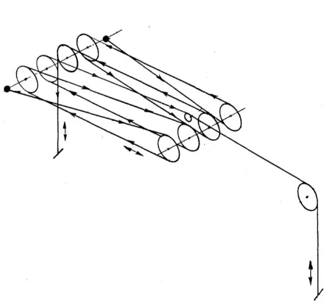
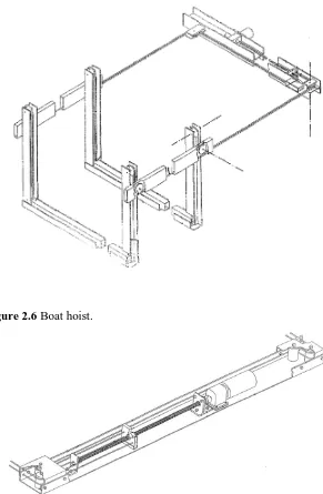
2.5.3 Patent - floating dock and boat lift
23
Figure 2.6 Boat hoist.
Figure 2.7 Screw lifting mechanism.
Mechanical advantage achieved by screw thread.
Use of multiple wires possible.
Even movement of each wire due to single lifting point negates need for levelling mechanisms.
Option of low voltage motor powered and independent power supply via batteries.
24
2.5.4 Patent - boat hoist
This patent (Byron L. Godbersen 1983) is for a hand powered hoist and its main design feature is the system for maintaining a level hoisting platform, free of twisting during operation.
[image:35.595.188.463.159.403.2]Figure 2.8 Free standing boat hoist.
Figure 2.9 Wire system for free standing hoist.
Single lift wire acting via pulley to two lifting points. Ensures even lifting of hoisted side.
Self levelling wires across ends of hoisting platform.
25
Additional 2:1 mechanical advantage achieved by pulley (item 66) and single hoisting wire (item 62).
2.5.5 Patent - powered boatlift with electronic controls
This patent (Wayne G. Floe 2006) describes a boat hoist with a single hoisting point at one of the 4 corners of the lifting platform. The lifting platform is kept level by the application of 3 self levelling wires in a similar fashion to previous patents. The key additional features in this design are related to the electronic control of the hoisting system.
[image:36.595.187.446.281.504.2]
Figure 2.10 Wire drawing of hoisting and levelling system.
Wire 42 is the single hoisting wire, wires 31F1, 31S1 and 31S2 are levelling wires to maintain a level hoisting platform.
Hoisting system is a powered screw thread housed within a horizontal member acting on a single hoisting wire.
Screw thread is driven by a reversible electric motor via first a belt drive, and secondly by a chain drive. Both sets of drive are geared to achieve mechanical advantage.
Adjustable feet for levelling hoist frame on uneven surface.
26 stopped.
Regenerative electric braking system to limit speed during lowering.
Mechanical limit switches driven from the gearbox output shaft stop hoist on upper and lower limits.
Reverse delay, to prevent shock loads resulting from sudden reversal of control signal.
Load sensing circuit (motor current monitor) locks out hoist if overloaded, requires manual reset.
Control by either manual push-buttons or by remote control.
2.5.6 Patent - programmable lift control
[image:37.595.165.433.407.632.2]This patent (James A. Endres 1997) discusses a control system for automatic hoisting of the platform. However, the hoisting system itself is different from previously examined designs.
Figure 2.11 Boat hoist winch and limit switch arrangement.
The wire drum in this hoist system is a length of pipe instead of the usual drum end.
27 difference in drum diameter causing uneven hoisting.
Magnetic proximity switches are mounted so they are operated by movement of beam (item 57) when contact is made with the wire (item 21) due to the changing angle as more or less wire is wound onto the pipe.
A possible improvement to this design would be to use a grooved drum which tends to locate the wire more positively, keeping the wraps tight.
2:1 mechanical advantage is achieved with pulley (item 37).
2.5.7 Patent application - electromagnetic release.
This latching system patent application (Wolfgang Raffler 2006) is for a vehicle hoist. The latch is based on a spring loaded latching pawl that engages with a perforated steel section. The latch pawl engages with each step in the perforation. When lowering the hoist the weight is taken off the pawl and then a solenoid retracts the pawl against the spring pressure. The solenoid is connected to the end of the chain shown in figure 2.12.
This particular latch is of interest because of the mechanism simplicity and the perforated plate is easily incorporated into this hoist.
28
2.5.8 Patent - hoist locking and release apparatus.
This patent (Jon S. Halstead 1998) describes a latch that uses a toothed plate to engage with the latch pawl. The difference here is the latch is fitted with a cam that releases the latch when the hoist is raised slightly. The latch remains disengaged until the hoist reaches the bottom, where the latch pawl ‘resets’, ready to engages with each tooth as the hoist is raised.
The key feature of this system is the latch is automatically released from its locked position when the hoist is raised slightly.
(a) (b) (c)
[image:39.595.171.480.236.657.2](d) (e) (f)
29
2.5.9 Reimann & Georger Corp. Marine Products (RGC)
[image:40.595.146.506.147.405.2]RGC Marine Products (Reimann & Georger Corp 2006) manufacture boat hoists such as the one below:
Figure 2.14 RGC vertical boat lift.
Vertical Boat Lifts rated from 500kg to 4500kg.
Frame Marine grade aluminium.
Stainless steel cables and hardware.
Polymer sheaves for maximum cable life.
Hand powered or optional electric friction or electric power drive.
30
[image:41.595.241.411.56.290.2]Figure 2.15 RGCs AC or DC Friction drive attached to hand powered hoist winch.
[image:41.595.243.414.397.620.2]31
2.5.10 Flat-plate boat hoist
This flat plate winch (Boat Hoist USA 2008) is specifically designed for boat hoists. Boat Hoist USA is also a retailer of boat hoists, parts and other marine equipment.
The flat plate boat hoist is an off the shelf electric powered winch drive. The electric motor drives a 5:1 Vee-belt reduction which in turn drives a 96 tooth worm wheel.
The winch plate is designed to be attached to a 2” diameter shed 40 pipe or grooved wire drum around which the hoist cable is wound. Any changes to this will void the lifetime warranty. The flat plate winch is not a load bearing unit, weight of the lift and lifting hardware needs to be supported by suitable bearings fitted to the winch pipe.
[image:42.595.261.389.336.517.2]
Figure 2.17 Boat Hoist USA BH70 7000 lb (3075 kg) flat plate winch.
2.5.11 Summary of hoist and hoist system designs
The hoisting system can be divided into sections for the purpose of evaluation. Below is a summary of potential solutions gathered by evaluation of existing products in chapter 3 and a general brainstorm for ideas.
Hoist power system. A study of the existing product available identifies the following methods of powering the hoist system:
32
screw thread, electrically driven, though could be hand driven;
geared hand winch drum;
geared electric drum winch; and
direct mechanism i.e. rack, ratchet hoist, chain hoist.
Mechanical advantage achieved by:
gearing in drive;
hydraulic power;
reeved wire rope; and
screw thread.
Hoisting medium:
wire rope;
chain;
soft strapping; and
direct drive screw thread.
Power source:
hand;
electric 240Vac;
electric low voltage DC; and
electric hydraulic.
Levelling system:
self levelling wires; and
multiple lift points.
2.6 Boat manufacturers
33 Length (M) Depth (M) Beam (M) Height on trailer (M) Weight boat only (kg) Maximum Engine weight (kg) Quintrex 395 Dart 4.00 0.91 1.69 1.5 95 90 420 Quintrex Dory
Wide Body 4.27 1.07 1.87 1.6 164 110
435 Hornet trophy 4.43 0.94 2.02 1.7 280 120 Qunitrex trailers
V-line Series
3.85-5.45 -
1.88-2.24 - 130-260 -
Alloy Craft 3.75
Open HD Cody 3.75 0.81 1.63 85 58
Ally Craft 3.95 Open
HD - Avalon 4.00 0.90 1.70 106 87
Ally Craft 4.25m
v-bow Shadow Deluxe 4.25 0.93 1.90 163 110
Ally Craft 4.25m
v-bow Shadow Mirage 4.25 0.93 1.90 200 110
Ally Craft 4.45m
Open HD - Sioux 4.45 1.16 2.25 223 120
Alloy Craft 4.95
Open HD - Abalone 4.95 1.22 1.95 270 178
Average 4.26 0.99 1.88 176 109
[image:44.595.113.546.51.471.2]Maximum 5.45 1.22 2.24 280
Table 2.1 Boat dimensions and weights.
This information is tabulated for review and establishing the design parameters for the hoist.
2.7 Component selection
34
2.7.1 Power screws
2.7.1.1 Introduction to power screws
Power screws transfer rotary motion to linear motion in a smooth manner. They are extensively used for lathe lead screws, screw jacks, valve stems, screw type presses, clamps etc (A.D. Deutschmann 1975).
There are two distinct classes of power screws, one uses various thread forms such as square thread, ACME thread, buttress threads and modified versions thereof. The second type uses a ball or roller screw system where rolling elements are used. The big advantage of the ball screw is the much higher efficiency, up to 90%, as opposed to around 70% for an acme thread.
Each thread type has its own advantages and disadvantages. The following summary has been put together from (A.D. Deutschmann 1975) and www.roymech.co.uk (Roy Beardmore 2008).
2.7.1.2 Square thread form
Highest efficiency all sliding thread forms.
Most difficult to machine.
Used for linear jacks and clamps.
Not very compatible with split nuts (split nuts are used to control backlash and compensate for wear).
35
2.7.1.3 ACME Thread
Earliest type of power screw used for lead screws on lathes.
Easier to manufacture than square thread.
Figure 2.19 ACME thread.
2.7.1.4 Buttress thread
Designed to resist loads in one direction only.
Stronger than other forms for given size due to greater root thickness.
Almost as efficient as the square thread.
Figure 2.20 Buttress thread.
2.7.1.5 Ball and Roller Screws
Ball and roller screws use rolling elements to support the load. The screws are machined to suit either ball or roller bearings. And the nut allows the balls to circulate as the screw is rotated.
36
Lower starting torque.
Predictable life expectancy.
Precise positioning and repeatability.
Smaller ball nut due to higher load capacity of balls.
Requires higher level of lubrication.
Needs additional braking system due to the high efficiency they are prone to rolling under static loads.
Susceptible to contamination.
Because load capacity is higher, the screw is not as stiff as an equivalent thread screw.
Figure 2.21 Recirculating ball screw.
Ball and roller screw manufacturers provide selection guides and example calculations for matching ball and roller screws to a particular task.
Ball screws nuts are not designed to support twisting forces on the nut. Therefore a nut guiding system will have to be considered.
2.7.2 Motor, gearbox and drive
Specialist advice was sought from SEW Eurodrive, Melbourne for motor, gearbox and drive selection. General requirements as follows:
Single phase power supply.
3 phase motor (lower cost and more options than single phase motors).
37 whenever power to the motor is removed.
Inverter single phase supply to 3 phase output. Allows acceleration, and speed control.
2.7.3 Self leveling wires
Self levelling wires have been used in several of the hoist patents reviewed. The wires are designed to keep the hoist platform level when a hoisting force is being applied to a single point on the hoisting platform.
[image:48.595.209.448.358.568.2]The wires interconnect two points on the hoisting platform. As one point of the hoist is moved by the lifting force, tension forces generated in the wire, create a resultant force acting upon the opposite corner, moving it in the same direction. The wire must be pre-tensioned and rated to full load as it is subject to the same force as the lifting wire.
Figure 2.22 Self levelling wire schematic diagram.
2.8 Conclusions
This chapter has outlined the background information required to design the hoisting system concepts.
38 A list of potential components for the hoisting system has been created and sorted into sections that make up a complete system. A combination of these items will be required to complete the design of the hoisting system. Each item will be evaluated for key features, advantages and disadvantages.
This information will be used in the next chapter to develop design concepts.
39
Chapter 3 - Hoist structure concepts
3.1 Introduction
This chapter outlines several design concepts, one of which will be chosen at the end and developed to the next stage, final design for prototyping. The design work has been divided into two sections, first the hoist arrangement, and second the hoisting system. This separation of the structure from the hoist system allows each distinct section to be assessed individually. Concepts will be detailed for each section and brought together in the decision phase.
At this time the structure drawings show the hoist concepts only and not the structural support, mounting or connections between the upright sections as this is considered to be outside the scope of this project.
To develop several design concepts the following process was undertaken: 1. Review existing products and other equipment for ideas.
2. Carry out a ‘brainstorming’ step to come up with distinct concepts with a high level of variation.
3. Reject concepts that are deemed not suitable.
4. Refine the chosen concepts during the drawing and detailing process. 5. Decide, which concept will be prototyped.
The decision process ideally is as objective as possible to best satisfy the requirements of the design. This way each concept will be treated without favouritism, and will be assessed against the same criteria.
3.2 Design criteria
Review of existing hoist designs and the requirement of SSRS have been used to develop the design criteria. This criteria will be added to as the design evolves.
40 likely to be uneven each lifting arm must be rated to support the entire load for each level i.e. 500 kg for each arm.
Stand alone structure. Hoist cannot depend on mountings for structural strength. This allows the hoist to be relocated by the user if required.
Separation between uprights, 2.75 m a compromise between the boat sizes in table
Separation between lifting arms, 1500 mm this allows sufficiently large tinnies with motors attached to be stored.
Lift vertical travel, 3000 mm this will allow the 1500 mm spacing between lifting arms.
Length of lifting arms, maximum of 2.4 m, this can be reduced in individual installations if required.
Minimal maintenance. Limited to greasing and inspection if possible.
3.3 Design concept one
3.3.1 Description
The key feature of this concept is the telescoped lifting arms where the upper lifting arm is guided inside the lower lifting arm. The lower lifting arm is guided within vertical structural sections.
41
Figure 3.1 Two views of hoist concept 1.
3.3.2 Advantages
Simple hoisting system where there is only a single connection between the hoist and the lifting arms.
Lifting arm guides telescoped together.
Minimal extra headroom requirement for vertical structural member.
3.3.3 Disadvantages
Upper lifting arm is telescoped within the lower lifting arm. Two different sizes of vertical section required. Two sets of strength calculations.
Potential for small amount of distortion to seize upper lifting arm in vertical guide assembly.
3.4 Design concept two
3.4.1 Description
42 solid rod fixed to the lower arm and extending vertically. The rod passes thru a clearance hole in the upper arm, when the upper arm is hoisted to approximately mid height the stop block on the connection rod contacts the upper arm causing the two arms to lift in tandem.
Figure 3.2 Two views of design concept 2.
3.4.2 Advantages
Adjustable height between upper 2 levels either during fabrication or possibly after installation by hoist operators.
Potentially more lifting arms could be added, each with lost motion solid rod connection.
Possible savings in manufacture due to each upper and lower lifting arms having several common components.
Minimal extra headroom requirement for vertical structural member.
3.4.3 Disadvantages
43
3.5 Design Concept three
3.5.1 Description
The main feature of this concept is the lifting arm bearing arrangement is external to the vertical guide post (dark blue). Each lifting arm is has two bearing assemblies linked by a plate section (aqua blue) with the (red) lifting arms attached. The two arm bearing assemblies overlap so that when the upper arm is lifted to approximately mid-height it makes contact with the lower lifting arm bearing assembly and both arms hoist together, in similar manor to concept 1.
Figure 3.3 Hoist concept 3, view of one upright showing lifting arms and bearing assemblies.
3.5.2 Advantages
Bearing assemblies are all the same reducing the overall number of components.
Vertical structure is a single column.
Large separation between bearing assemblies reduces forces on bearing assembly.
44
3.5.3 Disadvantages
Limited to 2 lifting arms only. More than 2 lifting arms would require either a much greater separation between each arms bearing assemblies or reduced head height between levels. Though it is possible this could be overcome by the use of additional sections to interlinked levels.
Additional headroom requirement, vertical structural section must extend further in this design due to the upper lifting arm bearing carried design.
3.6 Conclusions
45
Chapter 4 - Hoisting system options
4.1 General discussion
Hoist rated capacity is 2000 kg, this figure does not include lifting components, frictional losses, safety factor etc. Estimates of the lifting component weights, and the frictional losses, will be made as part of the final design. This will adequately hoist four boats with engines and typical equipment as detailed in Table 2.1, the largest boat, Alloy Craft 4.95 Open HD – Abalone, is considered to be the maximum size possible to hoist as the boat and engine have a combined weight of 448kg.
The use of wire rope is considered to be the most flexible and traditional method of connecting a hoisting system. Its advantages are flexibility in arrangement and easy adjustment. However, it does have a finite service life that varies greatly depending on environmental conditions.
The following hoisting system methods will be detailed for consideration:
Off the shelf chain block.
Electric flat plate winch.
Power screw.
Hydraulic cylinder.
Electric drum winch.
4.2 Off the shelf chain block.
4.2.1 Description
A 3t SWL chain block such as the ‘S’ Series chain block described on the
http://www.activelifting.com.au/liftingEquipment/chainBlock.htm requires 27kg of effort to lift the swl, this chain block is manufactured to AS1418.2
46 The use of a chainblock will require a system for connection of the two lifting arms to ensure even and level hoisting operation.
4.2.2 Advantages
Off the shelf complete solution.
Designed to technical standard AS 1418.2.
Internal gearing to achieve safe working load with minimal effort.
Internal braking system.
4.2.3 Disadvantages
Noisy.
Aesthetically unappealing to SSRS, although it is anticipated this can be overcome by fitting the hoisting chain internally within the upright structure and fitting covers.
Potentially difficult to adapt to powered operation, substitute electric chain hoist,
Self levelling system required.
4.2.4 Estimated cost
Item
Cost
Chain block 500
Sheaves and wire rope 1000
extras 1000
Estimated Total 2,500
Table 4.1 Estimated costs of chain block hoist.
4.3 Electric flat plate winch
4.3.1 Description
47 The hoisting plate consists of a dual voltage (110/240) electric motor driving a vee belt reduction which in turn drives a geared worm drive, see Figure 4.1. The plate is mounted with 2 bolts, and is designed to be connected to a length of 2” schedule 40 pipe, which is used as a cable drum. The winch plate is not designed to be load bearing, therefore the winch pipe must be adequately supported. A data table for a 7000lb winch plate is shown in Appendix D.
Figure 4.1 7000lb (3175kg) flat plate winch for boat hoists.
48
Figure 4.2 Example installation for flat plate winch and overhead hoist.
Summary of manufacturers installation recommendations from Boat Hoist USA electronic documents, (BoatHoistUSA 2008)
Ratings based upon winch pipe 2” shed 40, max OD 2 3/8” (60.325mm).
Unit can be mounted horizontally or vertically but must be at right angles to winch pipe.
Winch and bearings must be regularly greased.
Do not weld plate winch to structure, mount using any 2 of the 4 predrilled holes.
Allow to cool after 2 lifting cycles.
The hoist must be mounted at one end of the winch pipe.
Support required each side of the lifting points and every 3m along the pipe.
Cable winders are optional they increase cable life however decrease lifting capacity.
Cables must be correctly attached to pipe, manufacturer recommends drilling an appropriate sized hole through the pipe, perpendicular to the cable passing the cable through the pipe to the end and fitting a cable clamp pulling the cable back till the clamp comes up against the pipe hole.
49 Alternatively the same gear plate used in the BH70 is available separately with no motor for $559 USD, this allows a locally sourced electric motor to be used saving freight costs.
4.3.2 Advantages of flat plat winch
Off the shelf solution already widely used for hoisting boats for storage.
Simple arrangement for mounting winch and winch drums.
4.3.3 Disadvantages of flat plate winch
Slow, hoisting times is 6 minutes with a 50 hz power supply.
A significant problem has been identified with the use of this flat plate hoist, it relates to the diameter of the winch drum. The flat plate hoist is designed to operate with a 60.3 mm OD pipe as the wire drum, this diameter is much smaller than the minimum specified in AS 1418.1 (2002) Section 7.18.
Several variables were considered including reducing the service life of the wire to 5 years, and using a single reeved system to reduce wire tension. It is not possible to comply with the minimum drum diameters as specified by this standard using the 60.3 mm pipe.
The standard requires a drum to wire diameter ratio of 14. With a 12 mm wire this equates to 168 mm. Simply fitting the flat plate hoist with a 168 mm drum would reduce the lifting capacity by nearly 3 times, and void the manufacturers warranty.
4.3.4 Estimated cost
50
4.4 Power screw
4.4.1 Description
US Patent 5,655,850 Floating Dock and Boat Lift uses a power screw for the hoisting system.
Power screw and ball screw thread forms and advantages and disadvantages are outlined in chapter 2. For this hoist a roller or ball screw is viewed as the best option due to the increased load carrying capacity of the roller screws.
Ball screw nuts are not designed to withstand twisting forces, therefore an additional guide system for the nut will be required.
4.4.2 Advantages of a power screw
Excellent position accuracy.
Speed control by specifying thread pitch and drive speed.
High efficiency typically greater than 85per cent.
Low maintenance.
4.4.3 Disadvantages of a power screw
Cost.
Braking system required because of the high efficiency, static load can rotate the screw.
Loads need to be correctly guided as the screw nuts are not designed to support side loads.
Lubrication is critical and contamination of bearing by debris will greatly affect service life.
4.4.4 Options for utilizing a power screw
51 Option 2. Mount a single power screw horizontally within a structural member connecting the two uprights and use wires to connect to each of the lifting arms. This method would require increased spacing between the uprights and is therefore not suitable for this particular design.
Option 3. Each upright is fitted with a power screw. One power screw is fitted with a
motor and gearbox, the other screw is driven by a roller chain from the output shaft of the gearbox.
This option will be more expensive than the first two options due to the extra power screw and chain drive. It does have some advantages such as reduced loading on the power screws, eliminating the need for wire rope and sheaves to connect the lifting arms of each upright, and reduced size of the horizontal structure between the uprights because they need only support the tension in the drive chains.
This option also allows more than 2 uprights and an increased upright spacing. And will be more attractive where these requirements exist.
Option 4. Each upright is fitted with a power screw, gearbox, motor and brake. The power screws must be synchronised to ensure level hoisting and ensure the lift remains level over a number of hoisting cycles. The likely method of synchronising is synchronous motors and a digital position control system.
This adds a layer of complexity to the hoist which is viewed as not suitable for this particular application. However, as with option 3 this becomes more attractive with a greater number of uprights and increased spacing.
52
Brand Description Price
SKF SL40x20R roller screw assembly (no
bearings or machining included) A$4057.13 inc GST
THK Ballscrew TS5016+3500LT A$ 3,130 + GST.
Ballscrew Nut BTK5016ZZ A$ 1,170 + GST.
Fixed bearing BK40 A$ 1,022 + GST.
Supported bearing BF40 A$ 282 + GST.
Machining for Support Bearings A$ 550 + GST. Total A$ 6,769 inc GST Spiracon 40x24 Roller Screw #
SPT-040-24-3-RH-3500-3300-1-0 (based on 0.43 A$ to GBP $41,000 Guide rails and bearings for power screw nut A$2000-3000
Table 4.2 Component cost for power screw options.
The THK and SKF ball screws have a lower efficiency and load carrying capacity compared with the ‘Spiracon’ roller screw however for this application it doesn’t justify the price difference.
Linear Bearings Australia have provided a complete quote and screw selection data based upon the following data:
Vertical mounting.
Load mass of 2500 kg.
Hoist velocity 0.025 ms-1.
Stroke length of 3000 mm.
Acceleration time 0.5 seconds.
Fixed bearings at bottom end, support bearings at top.
Their recommended ball screw assembly has the following characteristics:
53
Calculated loading 24.7 kN.
Buckling load limit 58.6 kN.
Compressive load limit 213 kN. Which gives a static safety factor of 12.7.
Service life at loaded condition 7200 hours which is 7 times the estimated running hours.
Driving torque is estimated as 160 Nm and power 1.1 kW.
The THK selection data sheet is included in Appendi