This is a repository copy of
Estimation of Actuation System Parameters for Lower Limb
Prostheses
.
White Rose Research Online URL for this paper:
http://eprints.whiterose.ac.uk/102334/
Version: Accepted Version
Proceedings Paper:
Awad, MI, Abouhossein, A orcid.org/0000-0001-8697-1593, Dehghani-Sanij, AA et al. (4
more authors) (2016) Estimation of Actuation System Parameters for Lower Limb
Prostheses. In: 2016 11th France-Japan & 9th Europe-Asia Congress on Mechatronics
(MECATRONICS) / 17th International Conference on Research and Education in
Mechatronics (REM). MECATRONICS - REM 2016, 15-17 Jun 2016, Compiègne, France.
IEEE , pp. 354-359. ISBN 978-1-5090-1787-4
https://doi.org/10.1109/MECATRONICS.2016.7547168
© 2016 IEEE. This is an author produced version of a paper published in 2016 11th
France-Japan & 9th Europe-Asia Congress on Mechatronics (MECATRONICS) /17th
International Conference on Research and Education in Mechatronics (REM). Personal
use of this material is permitted. Permission from IEEE must be obtained for all other uses,
in any current or future media, including reprinting/republishing this material for advertising
or promotional purposes, creating new collective works, for resale or redistribution to
servers or lists, or reuse of any copyrighted component of this work in other works.
Uploaded in accordance with the publisher's self-archiving policy.
[email protected] https://eprints.whiterose.ac.uk/ Reuse
Unless indicated otherwise, fulltext items are protected by copyright with all rights reserved. The copyright exception in section 29 of the Copyright, Designs and Patents Act 1988 allows the making of a single copy solely for the purpose of non-commercial research or private study within the limits of fair dealing. The publisher or other rights-holder may allow further reproduction and re-use of this version - refer to the White Rose Research Online record for this item. Where records identify the publisher as the copyright holder, users can verify any specific terms of use on the publisher’s website.
Takedown
If you consider content in White Rose Research Online to be in breach of UK law, please notify us by
Estimation of Actuation System Parameters for Lower Limb Prostheses
M. I. Awad, A. Abouhossein A. A.
Dehghani-Sanij, R. Richardson, O. M. Querin
Institute of Design, Robotics and Optimization University of Leeds, Leeds, UK
David Moser, and Saeed Zahedi
Chas A Blatchford & Sons Ltd, Lister Road, Basingstoke, Hants, RG22 4AH, UK.
Abstract— This paper provides guidelines to estimate the kinematics, energy and torque requirements for lower limb prosthetic actuation systems during daily living activities. These parameters are estimated based on human biomechanical data from different sources to consider the variability due to the assumptions and errors in the analysis and data collection. The results showed that the powered actuation source is important at the ankle joint in the stance phase during level ground walking while it is more important at knee joint during stair ascending. These estimated parameters can be used as guidelines to design and select proper actuation systems.
Keywords- Knee actuator requirements; Ankle actuator requirements, Actuator selection.
I. INTRODUCTION
Every year around the entire world, thousands go through lower limb amputation operations due to complications of diabetes, circulatory and vascular disease, trauma, or cancer in limb segments [1]. Lower limb prostheses, which are devices that replace the lost limbs due to amputation or a congenital disorder, are used widely to restore the missing mobility functions. Despite the current technological advancement in prosthetics, amputees still suffer from gait asymmetry and high metabolic energy costs [2].
Although walking and daily living activities in able-bodied are learned under normal circumstances and done without conscious effort and involves complete gait symmetry, amputees require more mental effort to focus during walking to compensate for the deficiencies in the prosthetic. As unilateral transfemoral amputees are not able to deliver the correct power level at the right time, they suffer from noticeably abnormal gait, asymmetrical between both sides and increasing in energy consumption in comparison to able-bodied subjects [3-5]. The swing phase on the amputated side is longer than the non-amputated side and the double support phase in amputee tends to be longer than healthy subject. Consequently, the stance phase is longer and the swing is shorter than normal on the intact side. Moreover, the energy needed from transfemoral (TF) amputees to walk is more than both healthy subjects and transtibial amputees [1]. The walking speed is an important factor in amputees’ energy consumption as the faster an amputee walks the more energy is consumed for the same travelled distance. These deficiencies happen as the current prostheses could not supply the correct level of assistant at the right time.
In order to develop an efficient lower limb prostheses, the design specifications and requirements for prosthetic devices should be considered in a way to provide close performance to human locomotion [6]. Understanding and studying human
gait is an essential feature to examine and designing proper lower limb prostheses. The normal human gait cycle by convention encompasses the period from the heel strike of one leg to the next heel strike of the same leg and is divided into two phases. The portion in which the foot is in contact with the ground is called the stance phase and accounts for approximately 60% of the gait cycle while the swing phase happens when the foot is off the ground and occupies 40% of the cycle. The first part of the stance phase happens at heel strike (HS) when the knee is fully extended. Following the heel strike, the quadriceps contract strongly to prevent the knee buckling and then the foot and ankle dorsiflex to allow the forefoot to be in contact with the ground. The knee flexes about 15o to 20o during the braking double support (DS).
When the knee reaches maximum flexion in DS, it extends during single support (SS). As the body weight passes forward over the supporting leg, the Gastrocnemius Soleus contracts causing plantarflexion of the foot and ankle to give heel rise (HO) after which the knee flexes rapidly again in preparation for toe off (TO) [7, 8]. As the forefoot leaves the ground, the leg now starts the swing phase. In this phase, the swinging leg advances through the opposite extremity while the knee flexes and the ankle plantarflexes. The leg must slow down and the knee extends prior to heel strike (HS) by contraction of the hamstrings.
On the other hand, unilateral transfemoral amputees suffer from a lack of knee flexion/extension during the stance phase [4]. Knee flexion is normally not allowed during the stance phase because amputees cannot generate adequate extension torque about the knee joint to prevent buckling. In other words, the fact that the majority of commercial prosthetic knee and ankle joints are passive and poorly controlled means that transfemoral amputees show distinctly abnormal movements and power patterns. Although existing prosthetic feet depend on spring-like action to store the energy during heel strike and foot flat to use it at the late stance phase to initiate the swing phase, these prosthetic ankle-feet generate significantly less energy compared to normal healthy subjects. The challenges in providing prosthetic knees and ankles with correct assistant energy is the proper selection of the actuation system.
The aim of this paper is to identify the actuation system requirements for lower limb prostheses during level ground walking and stair ascending/descending in order to enhance amputee biomechanical walking performance and reduce gait abnormalities.
II. ACTUATOR SELECTION METHODOLOGY
torque ( ), maximum speed required from the actuator ( ), maximum position ( ) allowed by the mechanism, and the inertia of the mechanical components of the system [9-11]. The required actuators for the lower limb prosthesis’ joints are a significant issue because if the actuator power is underestimated, the adequate power is not delivered across the prosthetic joint to accomplish the intended function. On the other hand, if the selected actuator is overestimated/oversized, it could cost more and the system will end up with large and heavy actuation joint. The actuation transmission mechanism that is used to convert the motion type and amplify the torque delivered to the joint plays an important role in fulfilling the system requirements. The challenge in the actuation system design is to find the optimum combination of actuator, transmission mechanism and power source with minimum weight to produce the required torque and kinematics requirements.
III. ACTUATION SYSTEM REQUIREMENTS BASED ON BIOMECHANICAL DATA
There is a need to find and estimate the maximum peak torque, continuous rated torque, and maximum velocity for a healthy human knee and ankle joints during activities of daily life as a guideline for rough estimation of lower limb prostheses specifications and then select the proper actuation system. Therefore, normative clinical gait data for the knee and ankle joints of a healthy subject could be used. However, this approach has three shortfalls: 1) The human joint torque cannot be measured directly and calculated based on inverse dynamics models which are simplified models of human body. 2) There is no standardized protocol for using motion capture gait analysis laboratories related to the marker placement to reduce kinematic variability among several laboratories [12, 13]. However, biomechanists consider these errors and variability between studies are acceptable [14]. 3) Prosthesis inertia, geometry and mass are different compared to the human segments while the torque calculated from normative clinical gait data is based on human segments. Despite all differences, these calculated parameters can be used as a rough estimation in the design process and to indicate when the joints can regenerate energy and when they require actuation power.
For the knee and the ankle joints during daily activities, such as walking on level ground at different speeds and descending/ascending stairs with different inclination angles. Normative clinical gait data for the knee and the ankle joints of healthy subjects from previous research works [15-17] were used to calculate the joints requirements. The ascending and descending stairs data in [15] were collected from 10 healthy male subjects for 42o, 30o, and 24o inclination angle of
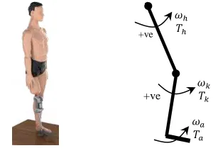
the staircase. The level ground walking data in [16] were collected from 19 healthy subjects for normal walking speeds. In order to check the repeatability and variations of the analysis to identify when the driving or braking (damping) torque is required during normal level ground walking, normative data from three different references [15, 16, 18] were used during level ground walking. The joint torque and angular velocity are considered to be positive in the anticlockwise direction as shown in Figure 1.
The moment and angular velocity during knee extension and ankle dorsiflexion are considered positive while knee flexion and ankle plantarflexion are negative. The continuous rated torque which is important in the selection of the actuator is calculated based on the torque profile during the gait cycle as shown in (1), and the energy generated or dissipated by the human joint is calculated from (2).
(1)
(2)
Where:
: normalised rated continuous torque (Nm/kg), : time (Sec.) such as stance time ( ), swing time ( ) or gait cycle ( ), : normalised torque (Nm/kg), : absorbed or generated normalized energy (J/kg), : joint angle (deg.), : joint power (W).
Figure 1. Skematic for lower limb prosthesis
The knee and ankle joint parameters during stance, swing phases and the whole gait cycle, shown in Tables I, II, III and IV, are extracted from the torque versus angle and torque versus angular velocity diagrams, shown in Figures 2,3,4, and 5 to provide a good baseline for the actuation system requirements during level ground walking. Hence, the actuation system should be capable to produce similar torque profile over stated joint angles.
IV. ACTUATION SYSTEM PARAMETERS FOR LOWER LIMB
JOINTS
A. Knee Joint Requirements during Level Ground Walking The average range of motion (RoM) of the knee angle is 58.65o±6.2o and the maximum angle ( ) 64.1o±0.7o
happens during swing phase. The maximum peak torque, which happens during single limb support in stance phase at 21.74o±2.8o, is generated to resist the knee flexion by applying
braking (B) flexion torque ( ) 0.5017±0.11 Nm/kg. This flexion knee torque is followed by generated (G) extension torque ( ) 0.49±0.068 Nm/kg to assist the knee extension in stance phase as shown in Figures 2 and 3. At the end of the stance phase prior to TO as shown in Figure 2, the knee joint accelerates to reach maximum flexion velocity in stance phase ( 50.05±4.3 rpm. The maximum angular velocity through the entire gait cycle happens during the extension
[image:3.612.353.503.288.396.2]swing phase ( 58.8±5.2 rpm. The rated continuous torque is function of the torque profile over the time. It has been calculated for stance, swing phases and the entire gait cycle as shown in tables I and II based on (1). In stance phase, the continuous torque is calculated as the actuator is engaged during the stance and disengaged during swing and the same calculations were done for the swing rated torque. These analysed data provide designers to select the proper actuator for individual gait phases or for the whole gait cycle. It was noticed that the actuator rated for the swing phase has less rated torque and maximum peak toque resulting in lighter actuator weight. On the other hand, the rated continuous torque for the entire gait cycle is less than the rated torque for stance phase alone.
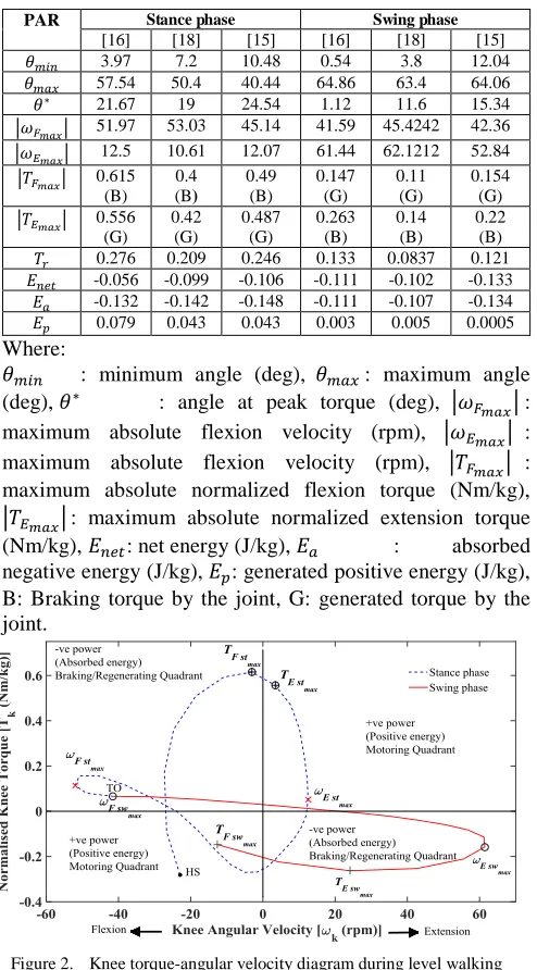
TABLE I. KNEE PARAMETERS DURING LEVEL GROUND WALKING AT NORMAL SPEED
PAR Stance phase Swing phase [16] [18] [15] [16] [18] [15] 3.97 7.2 10.48 0.54 3.8 12.04 57.54 50.4 40.44 64.86 63.4 64.06 21.67 19 24.54 1.12 11.6 15.34 51.97 53.03 45.14 41.59 45.4242 42.36 12.5 10.61 12.07 61.44 62.1212 52.84 0.615
(B)
0.4 (B)
0.49 (B)
0.147 (G)
0.11 (G)
0.154 (G) 0.556
(G) 0.42
(G)
0.487 (G)
0.263 (B)
0.14 (B)
0.22 (B) 0.276 0.209 0.246 0.133 0.0837 0.121 -0.056 -0.099 -0.106 -0.111 -0.102 -0.133 -0.132 -0.142 -0.148 -0.111 -0.107 -0.134 0.079 0.043 0.043 0.003 0.005 0.0005
Where:
[image:4.612.319.554.239.373.2]: minimum angle (deg), : maximum angle (deg), : angle at peak torque (deg), : maximum absolute flexion velocity (rpm), : maximum absolute flexion velocity (rpm), : maximum absolute normalized flexion torque (Nm/kg), : maximum absolute normalized extension torque (Nm/kg), : net energy (J/kg), : absorbed negative energy (J/kg), : generated positive energy (J/kg), B: Braking torque by the joint, G: generated torque by the joint.
Figure 2. Knee torque-angular velocity diagram during level walking
As shown in Tables I and II, the knee joint absorbs negative energy in stance, swing phases and also in the entire gait cycle more than generating positive energy. This means that knee joint requires to damp or dissipate energy more than generating during level ground walking. In order to know when the driving or braking (damping) torque is required during level ground, the diagram between the normalised knee torque ( ) and the knee angular velocity ( ) shown in Figure 2 provides more details. It is noticed that most of the gait cycle produces negative energy, which means that this energy should be dissipated either by braking or damping. This negative energy can be restored and converted from mechanical into electric energy as the case in regenerative braking concept instead of dissipating it in form of heat.
Figure 3. Knee torque-angle diagram during level walking
TABLE II. KNEE RATED TORQUE AND ENERGY DURING THE WHOLE GAIT CYCLE
PAR All Gait cycle [16] [18] [15] 0.2368 0.1743 0.2060 -0.1667 -0.202 -0.2390 -0.2428 -0.2488 -0.2813 0.0845 0.0479 0.0430
B. Ankle Joint Requirements during Level Ground Walking The total average RoM ankle angle is 29.5o±2.9o and the
maximum plantarflexion and dorsiflexion angles are 17.9o±1.8o and 11.6o±2.8o respectively. The maximum peak
torque happens during stance phase at the starting of foot plantarflexion (at 10.98o±3.02o) in order to give heel rise and
assist the ankle joint by applying driving (G) plantarflexion torque ( = ) 1.5±0.157 Nm/kg as shown in Figures 4 and 5. The ankle joint generates maximum braking (B) torque of 1.4±0.118 at the end of dorsiflexion in the stance phase ( ) to resist the body weight. The torque generated or absorbed in the swing phase is quite small in comparison to the torque in the stance phase. The maximum angular velocity ( 39.97±7.5rpm occurs during the ankle plantarflexion in the stance phase while the maximum dorsiflexion angular velocity happens in the swing phase ( is about 22.14±3.7 rpm.
[image:4.612.53.300.257.703.2]are shown in Table III. The negative energy absorbed during the early stance phase ( ) is smaller than the positive energy ( ) required for body propulsion during foot plantarflexion. The overall stored energy ( ) during the entire gait cycle is less than the required positive energy ( ) to drive the ankle joint as shown in Table IV. This means that the ankle joint cannot regenerate energy more than the amount it consumes. Therefore, the current passive based ankles with spring/ dampers may not be adequate to produce the required power during level ground walking.
Figure 4. Ankle torque-angular velocity diagram during level walking
Figure 5. Ankle torque-angular velocity diagram during level walking
TABLE III. ANKLE PARAMETERS DURING LEVEL GROUND WALKING AT NORMAL SPEED
PAR Stance phase Swing phase [16] [18] [15] [16] [18] [15] -19.77 -17.6 -10.38 -19.77 -17.6 -16.22
9.62 14.8 10.41 1.2 5 2.15 8.7 14.4 9.8284 -19.77 -17.6 -10.38 14.77 16.67 12.87 20.8 26.3 19.32 37.2 48.48 34.22 3.97 9.61 15.02 1.513
(B)
1.28 (B)
1.437 (B)
0.0190 (G)
0.01 (G)
0.022 (G) 1.623
(G)
1.32 (G)
1.542 (G)
0.023 (B)
0.01 (B)
0.029 (B) 0.871 0.733 0.873 0.0117 0.0132 0.0146 0.2189 0.2515 0.1593 0.0040 0.0027 0.0043 -0.122 -0.122 -0.103 -1*10-4 -5*10
-4
-9*10-4
0.3404 0.3741 0.2628 0.0042 0.0033 0.0053
Where:
[image:5.612.61.296.191.317.2]: maximum absolute dorsiflexion velocity (rpm), : maximum absolute plantarflexion velocity (rpm), : maximum absolute normalized dorsiflexion torque (Nm/kg), : maximum absolute normalized plantarflexion torque (Nm/kg).
TABLE IV. ANKLE RATED TORQUE AND ENERGY DURING THE WHOLE GAIT CYCLE
PAR All Gait cycle [16] [18] [15] 0.7079 0.5861 0.68 0.2229 0.2542 0.1636 -0.1226 -0.1233 -0.1047 0.3446 0.3774 0.2682
The joint RoM, torque-angle profile, maximum angular velocity, peak torques (braking (B) or driving (G)), , , , and are the main criteria to select the combination of the actuators and the actuation mechanism. These parameters provide an approximated guide to select a proper actuation system to drive the prosthetic knee and ankle joints. C. Knee joint Requirements during Stair Climbing
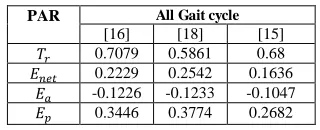
It is observed that most phases of stair descent produce negative energy as shown in Figure 6 and Table V, which means that this energy should be dissipated by damping or by mechanical impedance or recovered by regenerative braking. The regenerative braking might help in energy regeneration by converting the mechanical energy into electrical energy instead of dissipating it into heat by using mechanical braking or damping. It is clear that the greater the staircase inclination angle, the more negative energy is present which needs to be absorbed. However, very small portions of the single limb support and initial double stance phases require positive energy at smaller inclinations, which means that an actuation source is required at these times. Moreover, all the phases in stair ascending except the knee extension in the swing phase require positive energy, which should be provided by assistance of an actuator. This indicates that a damping effect is an important issue during descending stairs, but the actuation effect is more important during ascending stairs.
On the other hand, Figure 7 and Table VI show that positive energy and assistance torque are required to ascend stairs while braking torque are required for short period at the starting of ascending cycle. It is noticed that the angular velocity of the knee in swing phase during ascending is higher than the angular velocity required during stair descending and level ground walking at normal speed. Also, the maximum extreme knee angle which happens during ascending stairs with 42o inclination is 102.5o.
[image:5.612.53.297.352.490.2] [image:5.612.56.299.539.706.2]ascending an external positive energy should be added to the prosthetic knee to provide assistance and generate 1.167Nm/kg torque to ascend stair.
[image:6.612.67.286.336.686.2]Figure 6. Knee torque-angular velocity diagram during stair descending
TABLE V. KNEE PARAMETERS DURING STAIR DESCENDING
PAR Descending
42o [15] 30o [15] 24o [15] 13.2604 15.7284 13.5177 101.918
9
93.1674 89.1780
68.6098 57.8843 53.8429 41.1056 40.5198 42.2519 61.4154 56.7362 57.3118
1.4749 (B)
1.3507 (B)
1.2458 (B) 0
(G)
0.9447 (G)
0.9025 (G) 0.7096 0.6679 0.6064 -1.3634 -1.0433 -0.9304 -1.3634 -1.0612 -0.9438 0 0.0174 0.0129
Figure 7. Knee torque-angular velocity diagram during stair ascending
TABLE VI. KNEE PARAMETERS DURING STAIR ASCENDING
PAR Ascending
42o [15] 30o [15] 24o [15] 9.7808 8.966 8.5796 102.498 94.654 91.423 57.9898 51.9700 49.5555 85.6318 76.5972 72.668 34.3685 30.5986 31.7308
0.2439 (G)
0.2176 (G)
0.1763 (G) 1.1670
(G)
1.0985 (G)
1.0546 (G) 0.4476 0.4198 0.4052 0.6420 0.5574 0.5040 -0.0404 -0.0447 -0.0482 0.6823 0.6018 0.5521
D.Ankle Joint Requirements during Stair Climibing Figures 8 and 9 and Tables VII and VIII show the ankle joint torque-speed profile and the requirements during stair ascending and descending. The RoM of ankle joint during both stairs ascending and descending are higher than the RoM during level ground walking. This increase in the ankle angle is required in dorsiflexion direction to allow the foot to comply with the step height and inclination.
Figure 8. Ankle torque-angular velocity diagram during stair descending
TABLE VII. ANKLE PARAMETERS DURING DURING STAIR DESCENDING
PAR Descending
42o [15] 30o [15] 24o [15] -19.0664 -15.9032 -14.9198 25.3776 25.2446 28.2864 14.0112 16.1359 14.7372 54.6820 46.4007 43.0914 22.5633 24.6009 27.5592
1.1483 (B)
1.1142 (B)
0.9673 (B) 0.8926
(G)
0.8389 (G)
0.9637 (G) 0.6012 0.5926 0.5832 -0.3504 -0.2497 -0.2653 -0.4505 -0.3929 -0.3818 0.0999 0.1426 0.1163
Ank
[image:6.612.324.555.357.505.2]Figure 9. Ankle torque-angular velocity diagram during stair ascending
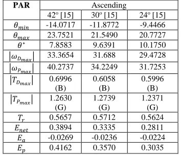
TABLE VIII. ANKLE PARAMETERS DURING STAIR ASCENDING
PAR Ascending
42o [15] 30o [15] 24o [15] -14.0717 -11.8772 -9.4466 23.7521 21.5490 20.7727 7.8583 9.6391 10.1750 33.3654 31.688 29.4728 40.2737 34.2249 31.7253
0.6996 (B)
0.6058 (B)
0.5996 (B) 1.2630
(G)
1.2739 (G)
1.2371 (G) 0.5657 0.5712 0.5624 0.3894 0.3335 0.2811 -0.0269 -0.0236 -0.0224 0.4162 0.3570 0.3035
It is noticed that negative energy is generated at the starting of either stair ascending and descending as shown in Figures 8 and 9. This energy can be stored and used later instead of dissipate it. The net negative energy is higher on the ankle joint during stair descending while the positive energy is higher during level ground walking and stair ascending. This means that more assistant source are required to drive the ankle joint during stair ascending and level ground walking.
V. CONCLUSION
This paper provides an estimated guideline for the kinematic and torque parameters which are required to design and select the joints actuation system in lower limb prosthesis. These parameters also can be potentially used for selection of exoskeletons and orthoses actuators. This estimation will be used to avoid either underestimating/overestimating the actuator requirements, which affects both the weight and the functionality of lower limb prostheses. It has been pointed out that during the majority of the level ground walking phases, negative energy
is absorbed across the knee joint which needs an impedance damping/braking control while a net positive powered source is required about the ankle joint specifically in the stance phase. Positive energy is required during some sub-phases of level ground walking to assist the knee joint. In case of stair descending, both the knee and the ankle joints generate net negative energy while positive energy are required from both joints during stair ascending.
ACKNOWLEDGMENT
Research supported by Engineering and Physical Sciences Research Council (EP/K020462/1) in the UK.
REFERENCES
[1] A. Cristian, Lower Limb Amputation: A Guide to Living a Quality Life: Demos Health, 2005.
[2] Y. Sagawa Jr, K. Turcot, S. Armand, A. Thevenon, N. Vuillerme, and E. Watelain, "Biomechanics and physiological parameters during gait in lower-limb amputees: A systematic review," Gait & Posture, vol. 33, pp. 511-526, 4// 2011.
[3] S. Jaegers, J. H. Arendzen, and H. J. Dejongh, "PROSTHETIC GAIT OF UNILATERAL TRANSFEMORAL AMPUTEES - A KINEMATIC STUDY," Archives of Physical Medicine and Rehabilitation, vol. 76, pp. 736-743, Aug 1995.
[4] R. E. Seroussi, A. Gitter, J. M. Czerniecki, and K. Weaver, "Mechanical work adaptations of above-knee amputee ambulation," Archives of Physical Medicine and Rehabilitation, vol. 77, pp. 1209-1214, Nov 1996. [5] A. H. Vrieling, H. G. van Keeken, T. Schoppen, E. Otten, J. P. K. Halbertsma, L. Hof, et al., "Gait initiation in lower limb amputees," Gait & Posture, vol. 27, pp. 423-430, Apr 2008.
[6] M. Pitkin, "What can normal gait biomechanics teach a designer of lower limb prostheses?," Acta of bioengineering and biomechanics / Wroclaw University of Technology, vol. 15, pp. 3-10, 2013.
[7] J. Perry, Gait analysis : normal and pathological function. Thorofare, N.J.: SLACK inc., 1992.
[8] B. R. Durward, G. D. Baer, and P. J. Rowe, Functional human movement : measurement and analysis Oxford: Butterworth-Heinemann, 1999. [9] M. Academy, Formulae Handbook: Maxon motor, 2012.
[10] U. Kafader, The selection of high-precision microdrives: maxon motor, 2012.
[11] S. Cetinkunt, Mechatronics with Experiments: John Wiley & Sons, 2015.
[12] M. G. Benedetti, A. Merlo, and A. Leardini, "Inter-laboratory consistency of gait analysis measurements," Gait & Posture, vol. 38, pp. 934-939, 9// 2013.
[13] G. E. Gorton Iii, D. A. Hebert, and M. E. Gannotti, "Assessment of the kinematic variability among 12 motion analysis laboratories," Gait & Posture, vol. 29, pp. 398-402, 4// 2009.
[14] J. L. McGinley, R. Baker, R. Wolfe, and M. E. Morris, "The reliability of three-dimensional kinematic gait measurements: A systematic review," Gait & Posture, vol. 29, pp. 360-369, 4// 2009.
[15] R. Riener, M. Rabuffetti, and C. Frigo, "Stair ascent and descent at different inclinations," Gait & Posture, vol. 15, pp. 32-44, Feb 2002. [16] D. A. Winter, The biomechanics and motor control of human gait :
normal, elderly and pathological, 2nd ed. Waterloo, Ont.: Waterloo Biomechanics, 1991.
[17] D. A. Winter, Biomechanics and motor control of human movement, 4th ed. Hoboken, N.J. : Chichester :: Wiley ; John Wiley, 2009.
[18] G. Bovi, M. Rabuffetti, P. Mazzoleni, and M. Ferrarin, "A multiple-task gait analysis approach: Kinematic, kinetic and EMG reference data for healthy young and adult subjects," Gait & Posture, vol. 33, pp. 6-13, 1// 2011.
Ank
[image:7.612.96.273.302.454.2]