ACB-3530A User's Manual
%"
Streaming Tape Controller
SCSI to QIC-36
Novem ber1986
@]
adoptee, inc.
_ . _
TABLE OF CONTENTS
SECTION PAGE
1.0
2.0
3.0
INTRODUCTION. • • . • • • •
1.1 ACB-3530A FEATURE SET.
.
..
.
.
.
.
.
.
.
.
.
. .
...
REFERENCE DOCUMENTS. • • • . • • .
ACB-3530A CONTROLLER BOARD L~YOUT.
• • 1-1
• • 1-1
· • 1-1
· . 1-2 1.2
1.3
1.4 PRODUCT SPECIFICATION • • •
1.4.1 PHYSICAL DIMENSIONS • .
. . . 1-4
. . . . . . . 1-4
1.4.2
1.4.3
POWER REQUIREMENTS. . • • •
ENVI RONMENTAL REQUI REt-1ENTS.
THEORY OF OPERATION • • • • • •
2.1 ACB-3530A ARCHITECTURE • .
2.2 MICROCODE STRUCTURE. •
2.3 SELF TEST. • • • . • • • • .
INSTALLATION. • • • • • • • • • • • • • .
3.1 UNPACKING. • . • • . • .
3.2 PREPARATION OF INSTALLATION AREA.
3.2.1 MOUNTING CONSIDERATIONS • • • • . • .
· . 1-4
• • 1-4
· • 2-1
· • 2-1
• . 2-2
2-4
· • 3-1
· . 3-1
· • 3-1
· • 3-1
3.2.2 RF CONSIDERATIONS . . . • 3-2
3.3
3.4
ACB-3530A CABLING. . .
3.3.1 ACB-3530A POWER CONNECTOR, J4 •
ACB-3530A CONFIGURATION. . .. . . .
3.4.1 SCSI BUS ADDRESS • •
3.4.2 SCSI BUS PARITY DISADLE • • .
3.4.3 SCSI BUS PARITY OPERATION • • • . 3.4.4 SCSI RECONNECT.
i
3-2
3-3
3-3
3-3
• .. 3-4
· • 3-4
· • 3-5
SECTION PAGE
.. 3-5
4.0
5.0
3.5 POWERING ON THE ACB-3530A • • • . • •
QIC-36 1/4" STEAMING TAPE INTERFACE .
4.1 QIC-36 INTERFACE SIGNALS • • .
4.2
4.3
BLOCK FORMAT • •
4.2.1 FILE MARKS.
TRACK LAYOUT • • • •
4.4 TAPE MEDIA DEFECT HANDLING • • • .
SCSI INTERFACE DESCRIP·rION. • • • •
5.1 GENERAL DESCRIPTION OF SCSI • • • •
5.2 SCSI BUS SIGNALS • • •
5.3 SCSI BUS PHASES • • •
5.3.1 BUS ~REE PHASE.
5.3.2
5.3.3
5.3.4
5.3.5
5.3.6
ARBITRATtON
PHASE •
SELECTION
PHASE •
RES
ELECTIONPHASE •
INFORMATION TRANSFER PHASE. •
5.3.5.1 COMMAND PHASE. • • •
5.3.5.2 DATA PHASE • • . • • • .
5.3.5.3 STATUS PHASE.
5.3~5.4 MESSAGE PHASE.
SCSI BUS PHASE SEQUENCING ..
• 4-1
4-1
4-3
· 4-3
• 4-4
• 4-4
.. • 5-1
.. .. 5-1
.. 5-2
.. . 5-4
.. 5-5
· 5-5
• 5-5
.. 5-6
• • 5-6
• • 5-8
· • 5-9
• 5-9
• 5-9
5.4 BUS CONDITIONS • • • • • . • • • • • . . • . .
5.4.1 ATTENTION CONDITION . . . . • •
5.4.2 RESET CONDITION AND ABORT MESSAGES.
.. 5-9
· 5-11
.. 5-11
· 5-11
5.5 SCSI BUS TIMING • 5-11
ii
SECTION
6.0
5.6
5.7
5.8
COMMAND DESCRIPTOR BLOCK •
COMPLETION STATUS BYTE
SCSI MESSAGE SYSTEM
..
. .
. . . .
.
5.8.1 SCSI MESSAGE DESCRIPTION
COMMAND DESCRIPTIONS. • • • • •
6.1 TEST UNIT READY COMMAND.
6.1.1 POSSIBLE ERROR STATES
6.2 REWIND COMMAND • • • • . • • • • •
6.3
6.4
6.5
6.6
6.2.1 POSSIBLE ERROR STATES •
REQUEST SENSE COMMAND. • • •
6.3.1
6.3.2
6.3.3
POSSIBLE ERROR STATES •
UNIT SENSE INFORMATION.
SENSE KEYS • • • • •
READ BLOCK LIMITS COMMAND.
6.4.1 POSSIBLE ERROR STATES •
SET PARAMETERS COMMAND . • •
6.5.1 POSSIBLE ERROR STATES •
READ COMMAND • • • • ~ • • • •
6.6.1 POSSIBLE ERROR STATES •
. .
.
,
.'
6.7 WRITE COMMAND. • • • • •
.
.
.
. .
. . .
6.7.1 FORCED STREAMING.
6.7.2 ENCOUNTERING END OF MEDIA •
6.7.3 WRITE ERRORS DURING BUFFERED MODE.
6.7.4 MEDIA DEFECT HANDLING • •
6.7.5 POSSIBLE ERROR STATES •
i i i
PAGE
5-15
5-16
5-17
5-17
• . 6-1
· • 6-1
. 6-2
6-2
• • 6-3
· • 6-4
• • 6-4
• . 6-4
· • 6-7
. 6-9
• • 6-9
· • 6-10
· • 6-11
6-1·2
• 6-13
· . 6-14
· 6-15
• • 6-16
· 6-16
• . 6-1 7
· 6-18
SECTION
6.8 WRITE FILE MARK COMMAND • • • .
6.8.1 POSSIBLE ERROR STATES.
6.9 SPACE COMMAND. • • • • • • • •
6.9.1 POSSIBLE ERROR STATES •
6.10 INQUIRY COMMAND.
6.10.1 POSSIBLE ERROR STATES.
6.11 VERIFY COMMAND.
6.11.1 POSSIBLE ERROR STATES.
6.12 RECOVER BUFFER DATA COMMAND • • . .
PAGE
• • • 6-19
· . 6-20
• 6-21
· • 6-22
• • 6-23
• • 6-24
• • 6-25
· • 6-25
6.12.1 POSSIBLE ERROR STATES.
.
.
.
.
· • 6-26
6-27
6.13 MODE SELECT COMMAND • •
· .
.
.
.
.
.
16.13.1 POSSIBLE ERROR STATES • •
6.14 RESERVE UNIT COMMAND
·
·
·
·
·
6.14.1 POSSIBLE ERRO.R STATES.
6.15 RELEASE UNIT COMMAND
·
· ·
·
·
·
6.15.1 POSSIBLE ERROR STATES.
.
.
·
6.16 ERASE COMMAND.
. .
. ·
·
·
· ·
·
6.16.1 POSSIBLE ERROR STATES.
·
6.17 MODE SENSE COMMAND
.
·
·
· · ·
16.17.1 POSSIBLE ERROR STATES •
6.18 LOAD/UNLOAD UNIT COMMAND • • •
6.18.1 POSSIBLE ERROR STATES. • .
iv
400112-00A
·
·
·
·
·
·
·
·
· ·
·
·
· ·
·
· • 6-27
6-30
· ·
6-31· ·
6-316-32
·
·
6-32·
·
6-33· ·
6-33· ·
6-34• • 6-34
6-35
· • 6-36
LIST OF TABLES
TABLE
3-1 ACB-3530A CONFIGURATION JUMPERS, J6 • •
4-1 QIC-36, J1, CONNECTOR PIN ASSIGNMENTS.
5-1 SCSI CONNECTOR, J3, PIN ASSIGNMENTS
5-2 INFORMATION TRANSFER PHASES • • • •
~
.
.
.
"".' ~.
PAGE
• 3-3
• 4-1
5-3·
• 5-7
5-3 SCSI MESSAGES SUPPORTED BY THe ACB-3530A. • 5-17
6-1 ACB-3530A SCSI COMMAND SET.
6-2 ACB-3530A SENSE KEYS.
6-3 SPACE SEARCH CODES. •
LIST OF FIGURES
FIGURE
ACB-3530A BOARD LAYOUT. •
2-1 ACB-3530A BLOCK DIAGRAM
2-2 ACB-3530A CONTROLLING FIRMWARE.
.
.
3-1 ACB-3530A SYSTEM CABLING. • • • •
3-2 POWER CONNECTOR, J4, PIN ASSIGNMENT
4-1
4-2
5-1
5-2
5-3
5-4
orC-ll AND QIC-24 BLOCK FORMAT. .
1/4" TAPE LAYOUT.
TYPICAL SCSI CONFIGURATION.
REQ/ACK HANDSHAKE • . . •
SCSI BUS PHASE SEQUENCING ..
SCSI BUS TIMING • .. . .. •
v
400112-001\
• 6-1
. . . 6-7
• • • 6-21
PAGE
· 1-3
.
.
.
.
• 2-2• 2-3
• 3-2
3-3
4-3
· 4-4
5-2
· 5-8
• 5-10
· 5-12
FIGURE
5-5 CLASS 0 COB SUPPORTED BY THE ACB-3530A.
5-6
5-7
6-1
6-2
6-3
6-4
6-5
COMPLETION STATUS BYTE. • • •
IDENTIFY MESSAGE. • • •
TEST UNIT READY COMMAND
REWIND COMMAND.
.
. .
REQUEST SENSE COMMAND • •
SENSE INFORMATION • • •
READ BLOCK LIMITS COMMAND
6-6 READ BLOCK LIMITS DATA RETURNED • • • •
6-7 SET PARAMETERS COMMAND. • . • • • •
6-8 READ COMMAND. • • • •
6-9 WRITE COMMAND • • • •
6-10 WRITE FILE MARK COMMAND .
6-11 SPACE COMMAND • •
6-12 INQUIRY COMMAND
.
.
. .
. .
.
.
. .
.
.
PAGE
· 5-15
• 5-16
5-18
.'
.
• 6-2 • 6-3• 6-4
· 6-5
6-9
• 6-9
• 6-10
• 6-12
• 6-14
· 6-19
. • 6-21
• 6-23
6-13 INQUIRY DATA. • • • .
.
. .
.
.
.
• • 6-246-14 VERIFY COMMAND. • • •
6-15 RECOVER BUFFER DATA COMMAND • •
6-16 MODE SELECT COMMAND • • • • • • • •
. .
6-1 7 MODE SELEC'r CONFIGURATION DATA BLOCK. •
6-18 RESERVE UNIT COMMAND. •
6-19 RELEASE UNIT COMMAND.
6-20 ERASE COMMAND • • •
. . .
.
.
.
6-21 MODE SENSE COMMAND.
6-22 LOAD/UNLOAD COMMAND •
400112-00A
vi
• 6-25
• 6-26
• • 6-27
· 6-29
. • . . • . 6-31
• • • e e _ • 6 ... 32
· 6-33
6-34
• 6-35
1.0 INTRODUCTION
The Adaptec ACB-3530A streaming Tape Controller ~oard interfaces
a 1/4" streaming tape drive using the QIC-36 interface to any
host interface compatible with the ANSI X3.331 - 1986 Small
Computer System Interface (SCSI).
1.1 ACB-3530A FEATURE SET
• Full SCSI specification, ANSI X3.33l - 1986 compatibility.
Connects to any SCSI standard host adapter.
- SCSI bus arbitration and· disconnect/reconnect support.
Overlapped disk/tape operation capability with multitasking
I/O SUbsystems.
• Buffered write and immediate command completion support.
Data buffering and immediate completion mode for streaming on
systems that do not support SCSI bus disconnect/reconnect.
• QIC-24 and OlC-11 media format support.
Capable of reading and writing OIC-24 and OlC-1l format tapes.
• 16-Bit CRe on each record and SCSI bus parity.
Data integrity is assured by reading the data and checking CRe
immediately after it is
written.eRe
is also
checked ontape
reads. In addition, SCSI bus parity is checked or generated
on all bus transfers.
• Automatic tape defect handling.
Media defects detected by the controller from read after write
will result in the data being rewritten in the next sequenti~l
block.
~ Reserve/Release.
The tape drive can be reserved by an attached host to restrict
other host accesses to the data.
1.2 REFERENCE DOCUMENTS
• ANSI X3.331 - 1986 Small Computer System Inter.face
Specifica-tion.
• QIC-24 Specification: Proposed standard for data interchange
on streaming 1/4" drives.
o QIC-ll Specification: Proposed standard for data interchanqe
on streaming 1/4" drive~.
o QIC-36 Specification: 1/411 streaminq tRpe drive hasic
inter-face.
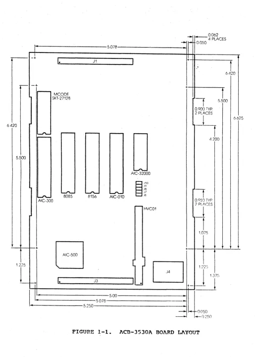
1.3 ACR-3530A CONTROLLER BOARD LAYOUT
The dimensions and component layout of the ACB-3530A is shown in
Figure 1~1. This diaqram is referred to later in the manual for
the location of the interface connectors, bus terminators, and configuration jumpers.
....
0062-iPLACES
---
I- 0.050I~ 5.078
1
-+
I.
I
+T
J1.
64.:.0
-
-+ -+1
MeODE
SKT-27128
-r
5.500
0.900 iYP 2 PIJ,CES
6.4
--~
6.62
20
--"'- I " ' - - r - - -
-5
tl200
5.500
l....n-AIC-32000
~"o
.19JH
f
~ ~ L..J"\..- ,J7
- " - 8085 8156 AIC-010 Jc
Ale-300 0.950 TYP.
t - -HVCQ1
? PLACES
_t
!
1.075
+
B
-+!
J
1.225
D
1:'2SL
1
137"I.
J3I
1--+ I--!
+-
J~
..
5.00..
.5 078
...
4 5.250 -
...
-
~ I-OOSO-
-()250FIGURE 1-1. ACD-3530A BOARD LAYOUT
[image:10.613.33.548.31.752.2]1.4 PRODUCT SPECIFICATION
The ACB-3530A contro11eris designed to function under normal
operatinq conditions for electronic components. The form factor
is'such' that the controller can be mounted with the drive in most systems.
1.4.1 PHYSICAL DIMENSIONS
Length: 8.00 inches (18.1 em)
Width: 5.50 inches (14.6 cm)
Height: 0.75 inches ( 1.9 cm)
1.4.2 POWER REQUIREMENTS
+5 VCD + 5% at 1.8 Amps (max)
+12 VDC-+ 10% at 100 mAmp (max)
1.4.3 ENVIRONMENTAL REQUIREMENTS
Temperature (F/C):
Humidity (non-cond): Altitude:
OPERATING
32% ° to 131°/55°
10% to 95%
o
to 10,000 MSLSTORAGE
-40°/-40° to 167°/75°
10% to 95%
o
to 10,OOOMSLExhaust air flow may be required to keep the airon both sirles of
the board at or below the maximum operatinq temperature.
2.0 THEORY OF OPERATION
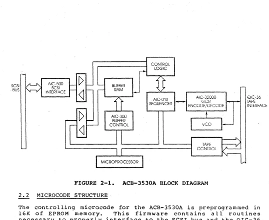
The ACB-3530A architecture
is
designed around the Adaptec controller chips~ the AIC-OIO and AIC-300. This architecture divides the controller into two basic components,~la data path and a control path. A block diagram of the ACB-3530A is shown in Figure 2-1.2.1 ACB-35!OA ARCHITECTURE
The ACB-3530A data path carries data to and from the attached Q·IC-36 tape drive and host. Data is transferred in an asynchronous fashion from the host to/from the controller BK-dual-ported buffer RAM. The buffer dual-port addressing and port handshaking is controlled by the AIC-300. Odd bus parity is checked on data tranoferred into the buffer and generated on data trans ferred onto the SCS I bus. The dua l-ported bu f fer is designed to allow data to be written into one port (i.e., from the host) as i t is being read out from the other (i.e., to the tape) in a FIFO fashion.
Data is transferred between the RAM buffer and the AIC-OIO
sequencer using synchronous timing to assure streaming operation. Data is converted into a serial NRZ data stream in the OIC-24 for mat by the A Ie - 010. . Th e Q I C - 24 I Dan d d a t a fie 1 d s are the n appended with CRC information. This NRZ data stream is encoded into the GCR encoding scheme and written onto the tape. As data is being written, the ACB-3530 is also performing a eRC check on the data and will rewrite blOCKS if any errors are detected.
An eight-bit microprocessor is used to initialize and monitor the status of the data path and serves as the main component of the control path. The microprocessor drives the SCSI control lines to sequence through the various bus phases and decodes a 11 SCSI
commands. The microprocessor is further used in the SCSI
interface to report
all
errors encountered and to transfer messages to the host.The microprocessor also performs the main controlling functions on the QIC-36 interface. These include trac'}{ select, motion control, and cartridge status (in or out).
SCSI BUS
AIC-500 SCSI INTERF.'\CE
AIe-·30G BUFFEI< CONTr"oL
CONTr<OL LOGIC
. AIC-010 SEQUENCER
AIC-32000 ...-. GCR
ENCODE/OECODE
[image:13.620.34.573.56.497.2]TAPE CONTr<OL
FIGURE 2-1. ACB-3530A BLOCK DIAGRAM 2.2 MICROCODE STRUCTURE·
QIC-36 rAPE IN1ERFACE
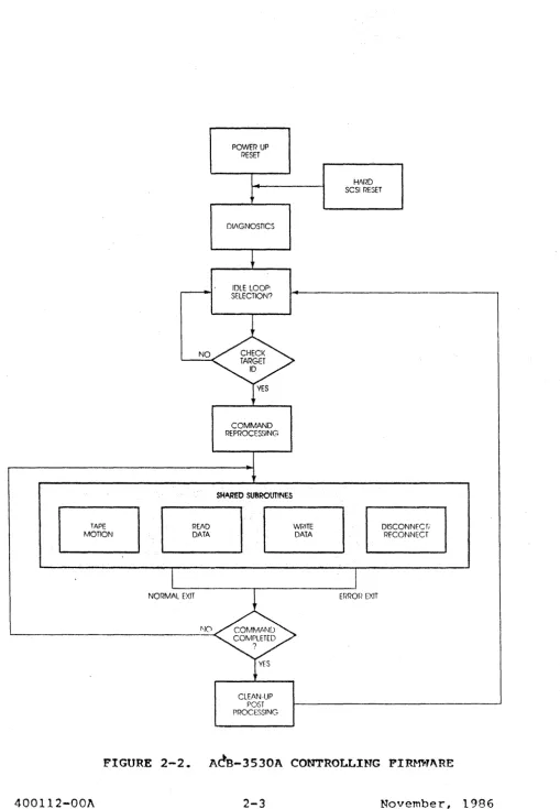
The controlling microcode for the ACB-3530A is preprograrnmed in
16K of EPROM memory. This firmware contains a 11 routines
necessary to properly interface to the SCSI bus and the QIC-36 interface and to control the tape data path. Figure 2-2 shows a basic flow chart for the controller firmware.
POWER UP RESET
HI\I<D
SCSI RESET
~
DIAGNOSTICS
---
IDLE lOOP:•
SElECTION?
NO CHECK TARGET 10
YES
COMMAND REPROCESSING
r
SHARED SU8ROUTlNES
TAPE
~
WPITE DISCONNEC r,.MOTION DATA . DATA RECONNECT
I
I
NORMAL EXIT mROP EXIT
~'J0 COMr-.l1r·ND COMPLETED
?
YES
CLEAN-UP POST PROCESSING
FIGURE 2-2. A~B-3530A CONTROLLING FIRMWARE
[image:14.618.57.567.41.777.2]2.3 SELF TEST
-The self test function is automatically executed on the ACB-3530A
upon power-up or after an SCSI reset. The self test executes in
300 ms, and during this time the controller will not respond to
any selection requests from the SCSI bus. During the test, the
red LED on the front of the board will be illuminated. If the
self test is failed, the LED will blink rapidly, at a rate of
approximately 4 Hz.
The loop-an-self test feature is invoked on the ACB-3530A by
holding SCSI ACK true while SCSI BSY is floating (false). During
this condition, the self test function will loop on itself.
3.0 INSTALLATION OF THE ACB-3530A
The ACB-3530A is designed to provide the performance and
"
flexibi lity required to reliably operate a QIC-36 1/4'" tape dri ve
for streaming backup of system data. Some basic installation
steps are required to assure proper board operation.
3.1 UNPACKING
The ACB-3530A is shipped in a protective carton with shock-absorbing and static protection material completely surroundinq
the ca rd. The ca rton shou ld be exa mined for externa 1 da mage as
i t is opened. The cards are physically inspected prior to
packaging, any damage noted should be reported immediately.
CAUTION: ALL CIRCUIT BOARDS CONTAININGVLSI CIRCUITRY HAVE SOME
SENSITIVITY TO ELECTROSTATIC DISCHARGE. THE ACB-3530A IS NO
EXCEPTION. PROPER HANDLING PRECAUTIONS. INCLUDING PERSONNEL AND
WORK SURFACE GROUNDING, SHOULD
BE
TAKEN TO PREVENT CIRCUIT STRESSWHICH CAN CAUSE COMPONENT F~ILURE.
3.2 PREPARATION OF INSTALLATION AREA
The ACB-3530A is generally designed into the physical host system
or a peripheral subsystem. Proper attention should be given to
the location of the ACB-3530A to assure that necessary
ventilation, ~nstallation clearances, and cabling paths are
provided.
3.2.1 MOUNTING CONSIDEP~TIONS
The ACB-3530A can be physica lly mounted using the four mounting
holes. These holes are in locations compatible with standard
5-1/4" Form Factor for.mounting onto the drive. The controller can
also be mounted onto custom designed brackets for alternate
mechan i ca 1 requi rements. Ca re must be ta ken, however, to
consider the physical forces the system will be subject to. No
conductive material should come in contact with the ACB-3530A PC
card.
3.2.2 RF CONSIDERATIONS
The J~CB-3530A and all other partially shielded electronic devices are sensititve to high power, high frequency or magnetic sources.
The con t ro lle r shou Id, be protected from such so~rces,:. In
particular, unshie lded switching, power supplies should be
ph Y sic a l l y i sola ted from a 11 e 1 e c t ron i c boa r d 5 and
interconnecting cables. Additional cable shieldinq may be
required' in some environments.
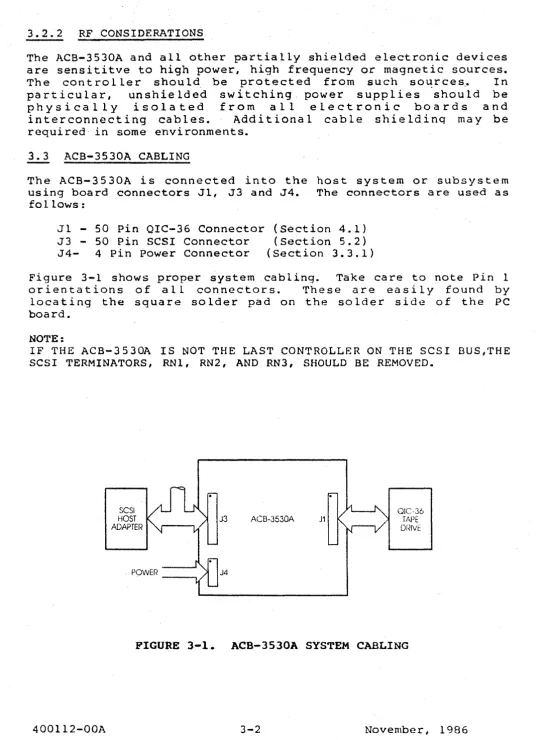
3.3 ACB-3530A CABLING
The ACB-3530A is connected into the host system or subsystem
using board connectors Jl, J3 and J4. The connectors are used as
follows:
Jl - 50 Pin QIC-36 Connector (Section 4.1)
J3 - 50 Pin SCSI Connector (Section 5.2)
[image:17.615.38.585.33.773.2]J4- 4 Pin Power Connector (Section 3.3.1)
Figure 3-1 shows proper system cabling. Take care to note Pin 1
orientations of all connectors. These are easily found by
locating the square solder pad on the solder side of the PC board.
NOTE:
IF THE ACB-3530A IS NOT THE LAST CONTROLLER ON THE SCSI BUS,THE SCSI TERMINATORS, RN1, RN2, AND RN3, SHOULD BE REMOVED.
400112-00A
SCSI
HOST
ADAPTEI< J3
J4
J1 QIC-36 TAPE
Df<IVt:
FIGURE 3-1. ACB-3530A SYSTEM CABLING
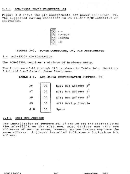
3.3.1 ACB-3530A POWiR' CONNECTORj J4
Figure 3-2 shows the pin assignments for power connector, J4.
The suggested mating connector to J4 is AMP P/Nl-480424-0 or
equivalent.
+12'1
+12'1 RETURN
+5V RETURN
+5V
FIGURE 3-2. POWER CO~mECTOR. J4, PIN ASSIGNMENTS
3.4 ACn-3530A CONFIGURATION
The ACB-3530A requires a minimum of hardware setup.
The function of J6 through ,,110 is shown in Table 3-1. Sections
3.4.1 and 3.4.2 detail these functions.
TABLE 3-1. ACB-3530A CONFIGURATION JUMPERS, J6
J6 00 SCSI Bus Address 2°
J7 00 SCSI Bus Address 21
J8 00 SCSI Bus Address 22
J9 00 SCSI Parity Disable
JIO 00 Spare
3.4.1 SCSI BUS ADDRESS
The in s t a 11 a t ion 0 f j u m per s J 6, J 7 and J 8 set the add res sID 0 f
,the ACB-3530A on the SCSI bus. SCSI devices can have bus
addresses of zero to seven, however, no two devices m~y have th~
same address. A jumper installed indicates a logicalone bit
address.
[image:18.618.32.575.34.761.2]3.4.2 SCSI BUS PARITY DISABLE
The installation of jumper J9 will disable the ACB-3530A odd bus
parity check on all data transferred from the host. If the
attached host dbes not ~enerate parity, parity must be disabled.
The ACB-3530A will always, generate odd parity on data transferred to the, host.
3.4.3 SCSI BUS PARITY OPERATION
The ACB-3530A incorporates full SCSI bus parity generation and
verification. The handling of parity errors by the controller is
detailed below.
Parity error on LD Message or Command Byte
A parity error on either an 10 message to the controller 6r on
the transfer of command bytes to the controller will result in
the command terminating after transmission of all six command
bytes with a Sense Key of 04h (Hardware Error) and Sense Byte 08,
bit 2 set.
Parity Error on Data to Controller During WRITE DATA
A parity error on data ,out to the controller during a WRITE DATA
command is latched and checked at the end 'of the transfer of each
blocK from the host. Detection of a parity error will result in
the command being terminated with a Sense Key of 04h and bit 2,
sense byte 09 set. The block which resulted in a parity error
will NOT be written onto the tape. The residue count will, as
usua 1, show the number of blocks remaining to be transferred to
the tape.
Parity Error on Message to Controller
On any Message Out to the controller, a parity error will cause the command in progress to be terminated with a Sense Key of 04h
and bit 2, sense byte 09 set. The message itself will be
ignored. This situation is always followed by a Status Out phase
(status
=
2), then by a Message Out phase, which terminates theconunand.
-~-.~.... .~: .::-...
--
~ ... ---.\lr,i't.l.at.or ~~t.ect:.e6 Errorj. In ai.;.. Cc.'s:::5. _ .. _~ ... :.' __ ::.:.:..~.": . . "
the command in progress terminating with 0. s::: :-.;::.~ !':: ; . : . : : .. : .:
(command aborted). For Read and Write commands, t:.~2-:~~:~_~
count will be valid.
For Read commands, any dat~ and/or status which resulted from "Lying Read" type operations (i.e., from the tape process being
ahead
at
the SCSI process) will be disregarded. The tape willthen be positioned at the end of the last record transferred to the host before the I n i t i a t o r Detected Error message was
received. ThUS, the host will be able to retry the operation by
backspacing the tape and rereading.
While transferring Data Out during a Read comma~d, the ATTN will
be checked between blocks to allow the host to notify the
controller of a parity error on Data In. It should be noted that
i f the host waits more than 128 blocks between the time i t detects a parity error on Data In and the time i t notifies the controller of this fact by raising ATTN and sending an Initiator Detected Error message, backspacing to recover from the error
will not be possible (as per current QIC-36 specification,
Reverse Space commando are limited to 128 blocks).
3.4.4 SCSI RECONNECT
When at tempting to reconnect after havi ng disconnected, the 3530A will wait 250 ms for the host to assertBSY after the
ACB-3530A has won arbitration for the bus. If the host does not
respond before the 250 ms expires, i t will clear the data bus and
check once more for BSY. If the host s t i l l has not responded,
the I/O operation is immediately terminated and no further attempts to communicate with the host will be tried without
rearbitration. See pages 5-6 and 5-12 in this manual for more
information on this feature.
3.5 POWERING ON THE ACB-3530A
The ACB-3530A, once properly cabled and configured, can be
powered-on. Power should not be applied to the controller i f
activity is present on the attached SCSI bus. The electrical
nature of the components typically used to drive this interface could interrupt bus activity.
If a cartridge is installed in the attached drive at power-on, the controller will rewind i t to BOT to prepare for read and write accesses.
If a cartridge is installed some time after power-on, i t will be rewound by the controller upon insertion.
The controller will present a Busy status to any access attempts made during the power-on cartridge insertion tape rewind.
4.0 QIC-36 1/4" STRE.1\MING TAPE INTERFACE
The QIC-36 interface provides a low-cost, high-performance,
standard interface for attaching a 1/4" stream1:,nq tape ·drive to intelligent controller/formatters. This section describes the interface between the ACB-3530A and a QIC-36 tape drive.
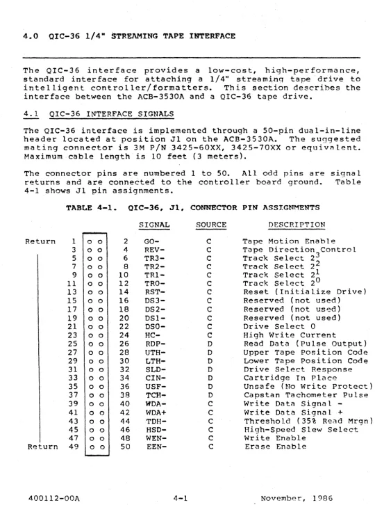
4.1 QIC-36 INTERFACE SIGNALS
The QIC-36 interface is implemented through a 50-pin dual-in-line header located at position J1 on the ACB-3530A. The suggested mating connector is 3M pIN 3425-60XX, 3425-70XX or equiv~lent.
Maximum cable length is 10 feet (3 meters).
The connector pins are numbered 1 to 50. All odd pins are signal returns and are connected to the controller board ground. Table
4-1 shows Jl pin assignments.
TABLE 4-1. OIC-36, Jl, CONNECTOR PIN ASSIGNMENTS
Return 1 0 0 3 0 0 5 0 0 7 0 0
9 0 0
11 0 0
13 0 0
15 0 0
17 0 0
19 0 0
21 0 0
23 0 0
25 0 0
27 0 0
29 0 0
31 0 0
33 0 0
35 0 0
37 0 0
39 0 0
41 0 0
43 0 0
45 0 0
47 0 0
Return 49 0 0
400112-00A 2 4 6 8 10 12 14 16 18 20 22 24 26 28 30 32 34 36 38 40 42 44 46 48 50 SIGNAL GO- REV- TR3- TR2- TR1- TRO- R8T- OS3- 082- 081- D80- HC- RDP- UTH- LTH- 8LD- CIN- U8F- TCH- WOA-WOA+ TDH- H8D- WEN- EEN-4-1 SOURCE
c
C C C C C C C C C C C D D Do
o
D D C C C C C C DESCRIPTIONTape Motion Enable Tape Direction Control Track Select 2~
Track Select 2
Track Select 21
Track SE! lect 2 0
Reset (Initialize Drive)
Reserved (not used)
Reserved (not us~d)
Reserved (not used)
Drive Select 0
High Write Current
Read Data (Pulse Output)
Upper Tape position Code
Lower Tape position Code
Drive Select Response
Cartridge In Place
Unsafe (No Write Protect)
Capstan Tachometer Pulse
write Data Signal
-Write Data Signal +
Threshold (35% Read Mrgn)
High-Speed Slew Select
Write Enable
Erase Enable
[image:21.620.44.585.52.779.2]A detail of the QIC-36 interface signals follows:
Go (GO-): Assertion of GO- causes a start tape motion sequence in
the direction specified by the state of REV-.
Reverse (REV-): Assertion of REV- will cause tape motion in the
reverse direction i f GO- is asserted. Deassertion of REV- wi 11
cause tape motion in the forward direction.
Track Select (TRO-. TRI-. TR2-. TR3-): Assertion of the track
select signals will result in the selection of track 0 through 3,
on a four-track drive, or 0 through 8, on a nine-track drive.
Track selection is made through binary assertion of these lines
with TRO- the least signifi~ant.
Reset (RST-): Assertion RST- will cause the tape drive to
reinitialize. This sequence differs between drive vendors.
Drive Select (DSO-)/Drive Selected (SLD-): The assertion of OSO-selects the attached tape drive to allow all tape operations to
proceed. The drive selected signal (SLD-) will be asserted by the
drive in response to selection.
High Current (HC-): Assertion of HC- enables the tape drive to use a higher write current when writing to the drive.
Read Data Pulses (RDP-): Serial read data is passed to the
controller as a pulse for every flux change. Since no read enable
is required, Read Data Pulses will be present any time data passes
under the tape read head and DSO- is asserted.
Upper Tape Hole (UTH-)/Lower Tape Hole (LTH-): The UTH- and
LTH-signals are generated by the drive to indicate some media status.
The BOT, Load Point, Early Warning, and EOT tape holes are encoded
to produce an output code indicating specific positions of the
tape. .
Cartridge In (CIN-): The CIN- signal is asserted by the drive
when a cartridge tape is fully installed and 050- is asserted.
The line is deasserted when the cartridge is removed.
Un sage (USF-): The USF- signal is asserted by the drive to
indicate that the installed cartridge is 'not write protected.
This signal will be asserted when the write protect plug is in the
unsafe position and DSO- is asserted •
.
,.'
Tachometer Pulses (TCH-): The tachometer pulses generated by the
rotation of the capstan motor inform the controller when the tape
is in motion and how fast. DSO- must be asserted for this signal
to be valid.
Write Data (WDA+, WDA-): WDA lines are differentia lly driven and
contain tape write data from the controller. WEN- must be
asserted prior to writing to the tape.
Threshold (THD-): Assertion of THD- invokes a 35% qualifying
amplitude for the read signal. This is typically used to
eliminate marginal tape recording areas.
High-Speed (HSD-): Assertion of HSD- causes 30 ips tape drive to
operate at 90 ips speed.
Write Enable (WEN-):
written to the tape.
Erase Enable (EEN-):
the full tape width asserted.
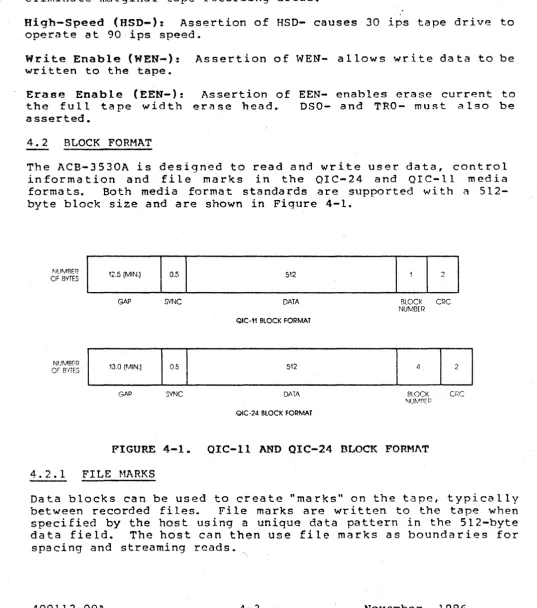
4.2 BLOCK FORMAT
Assertion of WEN- allows write data to be
Assertion of EEN- enables erase current to
err.! se head. 080- and TRO- mu~t a Iso be
The ACB-3530A is designed to read and write user data, control
information and file marks in the OIC-24 and orC-11 media
formats. Both media format standards are supported with a
512-byte block size and are shown in Figure 4-1.
BLOCK CRC NUMBER
BLOCK cr·:c
NU~}Pr:r~
FIGURE 4-1. OIC-II AND OIC-24 BLOCK FOR~mT
4.2.1 FILE MARKS
Data blocks can be used to create "marks" on the t.:\pe, typically
between recorded files. File marks are written to the tape when
specified by the host using a unique data pattern in the 5l2-byte
data field. The host can then use file marks as boundaries for
spacing and streaming reads.
' \
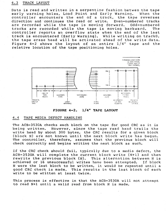
[image:23.615.34.571.157.765.2]4.3 TRACK LAYOUT
Data is read and written in a serpentine fashion betwen the tape
early warning holes, Load Point and Early Warning. When the
controller encounters the end of a track, the tape reverses
direction' and "continues the read or write. Even-numbered tracks
are recorded while the tape is moving forward. Odd-numbered
tracks are recorded while the tape is moving backward. The
controller reports an overflow state when the end of the last
track is encountered (Early Warning). While writing on trackO,
[image:24.615.34.583.54.751.2]the tape erase head will be activated ahead of the write data.
Figure 4-2 shows the layout of an entire 1/4" tape and the
relative location of the tape positioning holes.
fOf<WAf<U [)tl~fCfiON
ui f,\J'( Ifli,v'[l «().(ID( CiliA: GF
IN'I ShOWN j
rr<K5
-~.--4r--.-1
7 J .1
D
(,
2
-~--+-4r---=t===-' If,"b
-'4r-.4---$--f'HYSICf,L
lND 01 IAP[
· . ) l l " - I -.. - - - 4 S O ' - - - · - Y / ' - .... 1W·-._·lt!"'--wAf{NING
?ONl
I
lAr~LYWArmiNG
HI (~Ir,~ IIII( ~
FiECOflDINC 'lJ1~,~JINC (., 1,,1'1
ZOOt ,(A4f fIULl:.,
I
I (),'C'
f>(liNI
I
lJ,UNI\!lf-JC
<.A ".J-!
l'U;,lllnr'J
i·'H,·:A(>.1 LIt 'Jlf' ,I JIf ~(.,
Uf I ",d,
FIGURE 4-2. 1/4" TAPE LAYOUT
4.4 TAPE MEDIA DEFECT HANDLING
The ACB-3530A checks each block on the tape for good eRC as it is
being written. However, since the tape read head trails the
write head by about 300 bytes, the CRe results for a given block
(block N) are not known until. the next block write has begun.
The controller, therefore, assumes that the previous block wi 11
check correctly and begins writing the next block as such.
If the CRC check should fail, typically due to a media defect, the
ACB-3530A will complete the current block write (N+l) and then
rewrite the previous block (N). This alternation between N is
achieved or 16 unsu6cessful writes have been attempted. If block
N were the last block to be written, it would be repeated until a
good CRe check is made. This results in the last block of each
write to be written at least twice.
This process is effective in that the ACB-3530A will not attempt
to read N+l until a valid read from block N is made.
5.0 SCSI INTERFACE DESCRIPTION
This section briefly describes the SCSI protocol implemented by
th~ ACB-3530A. The SCSI protocols are further defined in the
ANSI X3.33l - 1986 specification.
5.1 GENERAL DESCRIPTION OF SCSI
~he SCSI is a device-independent method of interfacing up to
eight host computers and peripheral devices. Device independence
relates to the ability to communicate with a number of peripheral types without regard to the physical characteristics of the device (i.e., number of tracks, tape capacity, etc.).
The SCSI interface, based on the IBM block multiplexer I/O
channel, provides optimum performance in to-host and
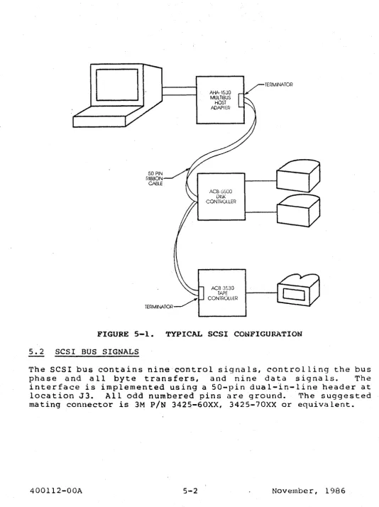
host-to-periphera 1 communication. . The SCSI is implemented through a 50-pin ribbon cable that is daisy chained to all attached hosts
and peripheral controllers. The SCSI can support up to eight
devices. A single device, such as a disk controller, can support
a number of peripherals. The daisy chained SCSI cable must be
terminated at both ends. Figure 5-1 shows the ACB-3530A in a
typical SCSI configuration.
Communication occur~ across the bus in a Request/AcknQwledge,
asynchronous fashion. The asynchronous bandwidth of the SCSI bus
is 1.5 Mbyte/sec maximum. When two devices communicate across
the bus, the device initiating "the command assumes an INITIATOR
role, the other device required to execute the command is
designated as the TARGET. Host computers are almost always
INITIATOR's, controllers are transferred and executed acrORS the
bus u sin 9 a n u m be r 0 f bus It ph a s e s. .. Th e ph a 5 e s d e t e r min e w hat
type of information (command, data, status, etc.) is being
transferred at any given time.
In order to execute a command, the INITIATOR (host) must first
gain control of the SCSI bus, this is accomplished through
arbitration. The host then selects the required controller.
From this point on, the controller determines all bus phases and
byte transfer~ The host interface must make no assumption
regarding the sequence of bus phases, as error conditions can
cause the controller to change the bus stat~ in the middle of
command and data transfers.
o·
50 PIN
f~IBBON
CABLE
AHA-15JO MULTIBUS
HOST ADAPIW
ACB·::i500
DI~K CONTf~Ol.LER
ACB3.530 TAPE
CONTr~OLLEr<
TERMINATOR
FIGURE 5-1. TYPICAL SCSI CONFIGURATION
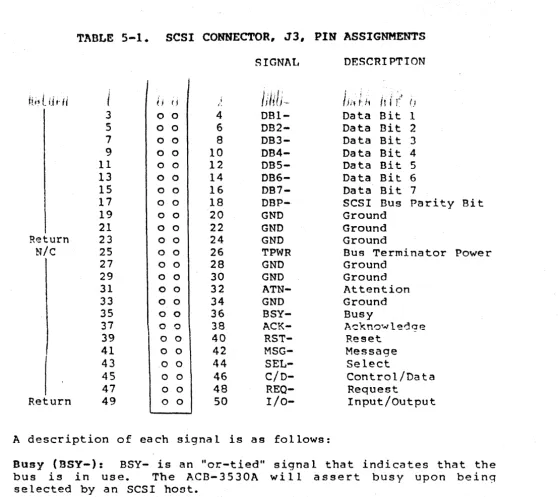
5.2 SCSI BUS SIGNALS
The SCSI bus contains nine control signals, controlling the bus
phase and all byte transfers, and nine data signals. The
interface is implemented using a 50-pin dual-in-1ine header at
location J3. All odd numbered pins are ground. The suggested
mating connector is 3M PiN 3425-60XX, 3425-70XX or equivalent.
[image:26.617.44.579.37.752.2]TABLE
5-1.
SCSI
CONNECTOR, J3,PIN
ASSIGNMENTS
SIGNAl,
DESCRIPTION
(J,I;
I 'Hi;
t
U
f-fi
11;,
I~ 1i; ; ,I
~ ,j ( j I ili(j,··, Hlf (I
i:.
3 0 0 4 DB1- Data Bit 1
5 0 0 6 OB2- Data Bit 2
7 o 0 8 DB3- Data Bit 3
9 0 0 10 OB4- Data Bit 4
11 0 0 12 DB5- Data Bit 5
13
0 0 14OB6-
DataBit
6 15 0 0 16 OB7- Data Bit 717 0 0 18 DBP- SCSI Bus Parity Bit
19 0 0 20 GND Ground
21 0 0 22 GNO Ground
~eturn 23 o 0 24 GND Ground
N/c
25 0 0 26 TPWR Bus Terminator Power 27 0 0 28 GND Ground29 0 0 30 GND Ground
31 o 0 32 ATN- Attention 33 0 0 34 GND Ground
35 o 0 36 BSY- Busy
37 0 0 38 ACK- Acknowl~dge
39 0 0 40
RST-
Reset41 0 0 42 MSG- Message
43 0 0
44
SEL-
Select45 0 0 46 C/O- Control/Data
47 0 0 48
REO-
RequestReturn 49 0 0 50 1/0- Input/Output
A description of each signal is as follows:
Busy (BSY-): BSY- is an "or-tied" signal that indicates that the bus i s i n use. Th e A C B ... 3 5 30 A wi 1 l a s s e r t bus y up 0 n be i n 9
selected by an SCSI host.
Select (SEL-): SEL- is an "or-tied signal that is used to select an SCSI device. The SEL- line can be used by a host to select a controller to initiate a command or by a controller to reselect a
host to complete a command (see section 5.3).
Input/Output (1/0-): I/O is driven by the controller to indicate
the direction of information transfers on the SCSI bus relative to the host. Assertion of this signal, In, indicates a
controller-to-host transfer. Out indicates a'host-to-controller trans fer.
[image:27.618.34.593.69.566.2]Control/Data (C/D-): C/O- is driven by the controller to
indicate whether a control or data byte is being transferred
across the bus. The type of control information is indicated by
the I/O line. Inbound, controller to INITIATOR, control
information is status. Outbound control information is commands.
I/O also indicates the direction of data transfers.
Message (MSG-): MSG is given by the controller to indicate a
request to send or receive an SCSI message. This signal will be
asserted when the controller desires to send a message, or, in
res po n se to t he h 0 s t as s e r tin 9 A TN - , in die a tin 9 a h 0 s t r e que 5 t
to send a message.
Attention (ATN-): ATN- is driven by the host to indicate a
request to transfer a message to the selected controller.
Request (REQ-): REQ- is driven by the controller to initiate the
REQ/ACK asynchronous handshake of a byte of information to or
from the host. The type of information is indicated by the C/D-,
1/0-, and MSG- signals.
Acknowledge (ACK-): ACK- is driven by the host to complete the
REQ/ACK asynchronous handshake of a byte of information to or from the host.
Data Bits and parity (DBO- to OB7-, DBP-):
eight-bit para llel bus, plus odd parity. significant.
The SCSI contains an
D80- is the least
5.3 SCSI BUS PHASES
The SCSI bus has eight distinct operational phases that are
controlled by the ACB-3530A by the assertion of one or more of:
C/O, I/O, MSG, SEL, and BSY. The eight phases are:
..
Bus Free•
Command*4W/ Arbitration
..
Data~•
Selection•
Status"•
Reselection u Message**Information transfer phases.
In execution of ~CSI operations, the bus will sequence through a
number of these ~hases. When the bus is between phases, the BSY,
SEL, REO, and ACK signals may not change. The C/O, I/O, MSG and
data lines may change.
The following sections describe the sequence of events contained within each bus phase, refer to Fiqure 5-2 and Section 5.5 for relative bus timing.
5.3.1 BUS FREE PHASE
The Bus Free phase, indicating that the bus is free and avail~ble
for use is entered by the deassertion and passiv~ release of all
bus signals. At the completion of an SCSI operation, the active
device(s) must deassert all bus signals within 800 ns of release BSY.
SCSI devices sense the Bus Free phase when SEL and BSY are deasserted and the Reset condition is not active.
5.3.2 ARBITRATION PHASE
The Arbitration phase allows one SCSI device to gain control of the bus in systems where more than one device may require the use
o f t he bus. Sy s t ems wit h on e h 0 s tan d S C SId e vice s t hat don 0 t
support reconnection may skip this phase by entering the Selection phase directly from Bus Free.
The sequence of arbitrating for the "bus is as follows:
1. Wait for Bus Free phase: deasserting of both SEL and BSY.
2. After Bus Free is detected, the arbitration device waits a
minimum of 800 ns (bus free delay) to assert BSY and the data bit corresponding to the device's SCSI address ID.
3. The arbitration device then looks on the data bus for an ID
of higher priority. If no higher priority ID's are present,
the device has won control of the bus. If higher priority
ID's exist the device returns to step 1.
4. After winning arbitration, the device asserts SEL and enters
the Selection or Reselection phase.
5.3.3 SELECTION PHASE
The Selection phase allows an INITIATOR (hosi) with control of the bus to select a TARGET (controller) to initiate an SCSI command.
The sequence for a host to select a controller is as follows:
1. To select a device in nonarbitrating systems, the host asserts the controller 10 address bit and optionally asserts i t ' s own 10.
When selecting a device from the Arbitration phase, the host already has SEL asserted (along with· BSY). The host asserts the controller ID and its own ID and then deasserts BSY.
2. On detecting the simultaneous condition of SEL and its own 10 asserted, and I/O and BSY not asserted, the selected controller examines the data bus for the host ID and responds
by asserting BSY.
3. The host then deasserts SEL and ID address data bits.
5.3.4 RESELECTION PHASE
The Reselection phase is used to re-establish a connection between a host and controller in order to continue a disconnected operation. This phase is entered from the Arbitration phase. Like the Selection phase, the SCSI device with control of the bus has both SEL and BSY asserted. The Reselection phase differs from the Selection phase by the assertion of I/O.
The sequence for a controller to reselect a host is as follows:
1. The controller asserts I/O and the data bits corresponding to its own In address and the desired host IO address. The controller then deasserts BSY.
2. On detecting the simultaneous condition of SEL, I/O and its own ID asserted and BSY not asserted, the reselected host examines the data bus for the controller ID and responds by asserting BSY.
3. After detecting the assertion of BSY, the controller also drives BSY and then releases SEL' and the ID address bits.
4. The host then deasserts BSY leaving the bus in the same state as at the completion of the Selection phase.
5.3.5 INFORMATION TRANSFER PHASE
The Command, Data, Status, and Message phases are used to transfer dat~~or control information across the data bus.
Th e C/O, I/O, and M S G s i 9 n a 1 s are use d to d i f f ere n t i ate the
various information transfer phases~ These signals are not considered valid unless REO is asserted. Table 5-1 shows the bus phases related to the C/O, I/O, and MSG signals.
TABLE 5-2 •. INFORMATION TRANSFER PHAS'f:S
SIGNAL
DIRECTION OF
MSG C/O I/O PHASE INFORMATION XFER
0 0 0 Data Out Phase Host to ACB-3530A
0 0 1 Data In Phase ACB-3530A to Host
0 1 0 Command Phase Ho~t to ACB-3530A
0 1 1 Status Phase ACB-3530A to Host
1 0 0 - Not Used
1 0 1 - Not Used
1 1 0 Message Out Phase Host to ACB-3530A
1 1 1 Message In Phase ACR-3530A to Host
NOTE:
"l" INDICATES SIGNAL ASSERTION (SCSI BUS SIGNALR ARE NEGATIVE
TRUE) •
The information Transfer Phases use the REO/ACK handshake to
control data transfers. Each REQ/ACK allows the transfer of one
byte of data. The handshake starts with the controller asserting
the REQsignal, requesting a byte transfer. The host responds by
reading or writing a byte of data from/to the bus and as~erts
ACK. The controller then deasserts REO, causing the host to
deassert ACK. See Figure 5-2.
A controller to host data transfer (I/O asserted) occurs with
the ACB-3530A placing data on the bus, assuring i t is valid at
the host interface, and asserting REO. The host then reads the
data and asserts ACK.
A host to controller transfer
(r/o
deasserted) occurs with thecontroller asserting REO, requesting a byte of data from the
host. The host places data on the bus, assuring i t is valid at
the controller interface, and asserts ACK.
The BSY signal remains asserted throughout the Information
Transfer Phases.
CON rROLLEI< l~lQ
h'--
CONIROLLER pr<ESENlS DATA\
/
0;-HOST ACK
t_
HOST TAKES DATA
\
0
COf\JTROLLER DATA
---(
>---\
ACB-3530 TO HOSr TRANSFERCONmOLLER REQ
/
CONrr~OLLER
TAKES
DATA~\
/
0
I
HOST ACK
~
HO~1 pr~bU\jTS
[)AIA
\
0HOSl DATA
- - - -
-<'---')-~
- - - -
-<----HOST TO ACB-3530 TRANSfER1 ~. SIGNAL ASSEI<TED o ,-SIGNAL DEASSmT[{)
FIGURE 5-2. REQ/ACK HANDSliAKE
5.3.5.1 COMMAND PHASE
The Command phase is used by the ACB-3530A to obtain Command
Descriptor Blocks (COB) from the host. The sequence for a
command transfer is as follows:
1. A host, in order to execute a command,· arbitrates for the bus
(if arbitrating system) and selects the ACB-3530A.
2. The ACB-3530A becomes selected and places the bus in a
Command phase with REO asserted. -.,
..
.
'3.. The command is passed, in a 6-byte block, to the ACB-3530A
using the REQ/ACK handshake and begins execution.
Section 5 .. 6 details the content of a SCSI Command Descriptor Block ..
5.3.5.2 DATA PHASE
The D~ta phase includes both Data In and Data Out. The Data In
ph a s e i 5 use d by t· he A C B-3 5 30A t o t ran s fer tap e d a tao r con t r 0 1
information (i.e., error codes or configuration data) to the
host. The Data Out phase is used by the host to transfer tape
write data or control information to the ACB-3530A.
The Data phase is typically entered after the Command phase and like command transfers, data is transferred using a RF:Q/ACK handshaking.
5.3.5.3 STATUS PHASE
The Status phase is used by the ACB-3530A to inform thehost of
the state in which the last command completed. The controller
can enter the Status phase at any time to indicate a detected
error. If an error is detected during the six-byte command
transfer, the ACB-3530A will transfer all six bytes and then
enter the status phase. The' controller wi 11 . immediate ly invoke
the Status phase if an error is encountered during a data
transfer. Status information is transferred in single byte from
the controller to host. Section 5.7 details the SCSI status
information.
5.3~5.4 MESSAGE PHASE
The Message phase includes both Message In and Message Out. The
Message In phase is used by the ACB-3530A to transfer acontrol
me s sag e t 0 the h 0 s t (i. e ., pre par e to dis con n e c t ) • Th e Me s sag e
Out phase is used by the hot to transfer a control messg~ to the
controller (i.e., abort operation). In order to enter the
Message Out phase the host must assert the ATN lin'e which causes
the controller to accept the message. Section 5.8 details the
messages supported by the ACB-3530A.
5.3.6 SCSI BUS PHASE SEQUENCING
The execution of commands typically consists of a number of SCSI
bus phases. Figure 5-3 shows a typical sequence of bus phases.
bUS FREE PHASE
~
ARBITRATION PHASE: HOST ARBITRATES AND GAINS CONTROL
OF BUS.
~
!F· DISCONNECT 1$ SUPPORTED; ATTENTION MESSAGE PHA::'E: HOST SELECTION PHASE: HOST INFORlvlS CONmOLLW OF
SELECTS CONTI<OLLER. • ;\BiLlTY 10 DISCONI'JECI. --ICENTlt=y
~
1ERROR COMMAND PHASE: HOST TiMNSI:ERS 6 BYTE MESSAGE PHASE: CONmOLLtr<
-... INIOI<MS HOST OF DI:::CONNECIION. COMMAND TO CONTROLLER -·SfWE D/\T/l., POINTEr?S
WITH [<EQ/ACK I-W-lDSHAKE.
----
.- DI$CONN[ CT~
!
BUS FREE PHASE mr<OR DATA PHASE: DATA
1RANSFEI<RED TO OR FROM
1
THE HOST.
ARBITRAfiON PHASE: CONmOLLm
~
A[~bllr~rtS TO r~fCONI·-.jECT ;'\NuGt,lNS CONTj~OL or Ti it: BUS
l
STATUS PHASE: CONTROLLER
-REPOf<IS STATUS 10 HOST.RESElECTlON PHASE:
CONlr<OLU:'!~ 1<[CONNEC1S TO HOST
~
!
MESSAGE PHASE: COMPLETION
._--
MESSAGE PHASE: CONTI<OllEr< MESSAGE DOH TRANSFER1<tD IDENIIFI[S r~f:CONNlCIlNG LuN.·--IL'[]o,jlifi TO HOST.
-- m::sror,E DATA POINTERS
~
...
"
BUS FREE PHASE
FIGURE 5-3. SCSI BUS PHASE SEQUENCING
5.4 BUS CONDITIONS
The SCSI bus has two conditions that can interrupt normal phase
sequencinq and initiate certa in device acti vi ty. These are the
Attention and Reset Conditions.
5.4.1 ATTENTION CONDITION
The Attention condition allows the host to signa~ the ACB-3530A
of a waiting message. The ACB-3530A accesses the messaqe by
invoking a Message Out phase and handshaking the message from the
host.
The host may create the Attention condition by asserting ATN at
any time except the Arbitration and Bus Free phase. When the
message byte is to be transferred the host deasserts the ATN signal once the Messaqe Out phase is entered.
The ACB-3530 A may not be abie to respond to the Attention
condition immediately so the host must continue to support the other bus phases while ATN is asserted.
5.4.2 RESET CONDITION AND ABORT MESSAGES
Th e Re set co n d i t ion i sus e d by the h 0 S t toe lea r all de vic e s fro m
the SCSI bus. This condition is created by asserting the RST
si~nal.
Reset can ccc~r at sny ~ime an~ ta~es preced~nce over all ot~er
bus phases and conditions.. On reset, all devices immediately
deassert and passively release all bus signals, thus entering a
Bus Free phase.
Th e R S T s i 9 n a 1 m us t s t a y ass e r ted for a t I e a s t 2 5 uS, w h i 1 e
asserted, no other bus signals can be assumed valid.
The ACB-3530A supports the SCSI "hard" reset mode. Upon reset,
the ACB-3530A releases all bus signals and immediately clears any
commands in process. The ACB-3530A will also rewind the tape to
BOT.
The next command to the ACB-3530A after reset will result in a
ChecK status. The Request Sense
(ISh)
commandwill
return asense key Unit Attention (6).
The ACB-3530A will respond identically to Abort Messages and SCSI
Reset Messages. The response will be a full reset of the
controller, exactly as an SCSI hardware reset.
5.S
SCSI BUS TIMING
SCSI bus timing is shown in Figure 5-4. The SCSI specification
can provide further timing detail if required.
f
"fll.1 '!lus ;CI Js~en")11 OCla, 01 IlSY" .,,,1 III;', lillie 110111 IlJ (1 H "S) ~Ii"," 01 "Du) Iitt IIlSV , do Sf.LI. r,ul l"""'I.':1"UuS 11tt Ol!iJ)' ¥. min t.Ine IhJ) IIl\j~( bt :t:1I tit!! ttiUli !Iii
Uu!; I..:CJI Ih:I;IV IUIIt! hi (:(:,11 tllllll l'li::' '11f1~1 tJllIil 1,1 'W;""" 1111 fj',~. Ifl;,: IJi,,,',l!
,:u .. :a~tl:llliJ (II !:.tL ItJj ... ILHI..tl.~u P:I<J)I; tJy l/iu..:r U'~h.t:. \(j(:I.J 11'..1
'A.b.lI.llyn 1II>Iay' fllin 111"8 110111 ;" •• 11""1 r~)'1
IG i,.iliH.~ ,t iClJllld1l0n i'i NUll l~ ~ .I~'
I
1.'IlU'
S.III~ ~.I; .. ( (4011 '''J~~~~---~----~~~
---,
J
(Ousy) -t-uSY \l---r...,...----t
(Stille!) "GEL
(Control/Data) -t-CiD (lnpuI:Oulpul) thO
(Request) ... P,EQ (Acknowleuyc) ,ACK
iAtttlfltlOIl) ,AlN
(Message) + M~G
(Rtset) ; nST
(D<lla Oil)
l
/
/
, DB (7-0, P) _....,... _ _ -Jir--___ ..;.;.;A',;;.bl;..;II.;..;lllJ,;;.'l .. I;;..() ',;;.' -+ __ -1" _ _ _ .. "...;"'..,;;',,1.;;.0;...;1,;;.[; __ "...;IJ;;..":..:"I...;I.;..Il _ _ _ r~'-_
/
/'
L
NoleUUI?I: ~1~~~,Jt;'tg~~'~~~;\'~II\\'lOI .I' U,II .. I,ua NOle
1111,1'1' ();.I,) ~J"ly 10,\(11 Pcully l~, ntll \fdluJ
dUfllltj ",tUffiltllUI
Trw U," oj ~.""~,, d
sy~lelll UVIIIlIi N,IIe
In;, IYIJlt:;11 ~j','jl~UI .Il't)/ilpuici ~
HuSI allal,t"1 'HIli d,:1 ,I> lIle "lflltlalor . ,illd.U11/Q
de\iICe ~ (oIIIIIlI unit WIlt ad
.o~ tnt! tJI(J"'
11 .. 1 •• 111,,111(:':.)
10 'lei bt,s
yt-
AkllllflAIIUN---l\..!
i\r-
t'11.\SE--v'
~
Aile. IIlIl'dlur~ci!~
l
J~~e'I,:JIII :h;;~~"&'SJltC ,"~ .. ,lob a 11,,1Ifhn til' lIu~ l't'l;
(Jtl:~;~\~I:'I'J~tl~U:~~II(~·lf
clS'le.I:. ts~y ,llId II~I
0/,11 10 Oil III" Ii.tld
Ou~
Alter 'lie ",0,11"1,,'11
l
'lCld V 11l."""JIOI~lIei:'s the d~I;1 lll" aurf rll:,1f~ tbt'lf "ulll
'" hili dhtlll " J Il:qher
I::;;g;~~/?, I~),~l::;~ 'Oil' .
II "~El.'
I.
"'''"''"~l
dunllY JIlUItlCC MOIIlJl'~1l o.e~".t!. tht' by'HltlalUf 'blil UllmetJ,· JlclY clea, ,I5cllll0111 , "rO,II;'(,uII ,,,,,!tun
_ Ilb:::e
~:~,~:,,~:I"~Jt'lI~:ltl
flHlH'S tt\.I1II"IJ~1I III
, .. Hit: ftlljlh:~l ,I'!\t,!IIt:11
then
I'
m.t .. lIul Lthlli~tJ .\HOY hilt'') lontll Jilt:' "".t.hlh) (1,\\) ~~I:- ~l'~aCtldJ'¥' I
5-12
11I1I1~t:;H II.)', IHJ~ ,HILI
:,t:lect~ l..l";!!t
1;L----IJtiI~~~pg~rll ~
L
~ I'ltA~t--V
IrUlidlh( "~~tllb ctJld bu',
- Willi lh::"IIIt!U tdillel ~ IU 6.
L
11""""(""",11",,10 11;0' Hl:;lll C II11N, I U ,~ J!>Oa".rt.d I
1\II~r 1"/1 'Clt:"ktN tlt!ltIY~
L
Un"'ItIII,dOI thn.,', B~;'I "II~ "tit'!' It!'tl IJI yl'l ... ~t~~ 1I!l~ flillddlllil 'JI B~d 11111l
,1',')l',h.:t!"tt,lI,lc ,0.1'" .O'",,',lell II,,, 1011'1,1 Sll & d~11{3?)~IIH.b (IY J')~t:t lllhl
AIIt'f t"AI" 11t.'~)jo.b'" (1t'I,.,,!
UlI' lal.kll.iI (llIlW ~)ll
L
dlHI m~\y Ch.l",j~ lilt: ,1.1i.1hliC;)
NlHe ,'\lIt'1 J.llllui.J1 ,:'t.tJ:'
~.t l II '" ~ 1\\" ".d, :'l/ ~
l
th".I{t'f',.tl.,IiL.l"l:,111.\It\ ,11t.1 J\IN I.tI'cllht' d.tl.1 tlla'\ If I i) I'. :.',if
.,,,,,"k,,,,,',I ... ,, .. ,.;,,,,,
IJltt IIUIII 111111,11\11 t
~".h·
l
J;H .;• •• .:" ::,'~ 01 ~ , ! \ ,I,. I ,
N·!\I:" I·, ~. ·,t, . ',.; ~"'",~r: ' • i : ,'.~ ... I "
1\1' ,"(_ .,,1 ,h,.: " ' t , ,. ,. ,LL I :.:.. .~(;:. ',:~"\ • _.
~S, \ ':,Lt 1,-.:, .J it. , : ~ ~ •• " ... Co '.IIt: \1 t: ,1, ' ~.: t" " " .\! ... , ~ .... ' .•• ' ! '
J. : r ; t'.:: .:.~ , ; ~ .!:.:. ~'; I )
':" ; ... :~ ,":;. h~ .. ~
.~- t L .,::;,' : ... ~ •.•• ,. 1"
~::.t 1 • '''c ".l.: .: _'. ~:. ..
• .. .,~.Io : . . : '
(Busy) +BSY
(Sp.ll!ct) I SEL
(Cnntrnl:Oata) ·r::o
(Input OutPIlt) "'110
(R~.qup.st) +REQ
(ACkr1I)wli'!dqe) , ACK
(Attention) .ATN (Messagp,) ~ MSG
(nesell I·AST
(O~la Bit! +00 (7-0.P)
400112-00A
"Bus sent .. rlplay" (~OO "51
----~+_---f~---_4---~---_{,J~---+---J-+---~rF---4-- - - ,
/ '
r',,1 eMO h-It.
r 11 fftf' I lI~qH"':f"
r (lfll/nalll! hom H1tIt,1tor
K:===
rOVMMII)PHASF~
L
Trl,qel~~<.'I~
L
,1~''-;'''1'f Ct(),IIHIIf,,'·f'.n()! ItO Ii'J,u:.(j
J\:t~t ;1 "hI!') ".·tlll'(jl'l,lV'rlf
1_
:I,:',II~::::"I:~'I,nr'~
!tll") fl,tlmm;lllt1, n"
L
1t,"h"'_O-"l_'-"",I'. .'('"kIM']f'1 w.HI', I
I
. ,"· ..
~,\N rtn.,y l.jI •. ~ .. 1t1f' J,Jt,1 ,\
-
~I~'::.'I:::I:~\,~,~I:,,!
MOr.'I"III."'!',"1..,. '1IItl,lIp, (h.-mlf, (1," ~f'W :h,.. flat' 1-"":11'11 r!rr:n~
r:r,; ,~.I.'-_,
~
nAIA.pl'~Sr
b
Pr,u'llrfll,h',' <I! ,h'v'rI'L_ l.U{f'" .v:-;,.Ttr; 1.'0' .Hut ,"1fI", 11'" :".,:,'r' r '0 Ilf
Ml.!,fj f;'1I\)I'tU',./lW;II' .... I(h·t',I,1 hI!' t'Ol!'
l
drl;ly 111'1",", ""rrtlfm'11f)_ Tarq,., ill~1) llutt; Ita',l nil IllP hll'-lt ,1t If';l'~t
L
In'h,lIOI rlf'\w,'"" I~;.'''; '~:lt.l_ln~ (:I!LI¥ t\,·llIff'1l1l',1'·51'!t1i"1~d "":'1,,1', A.GK .!fOL
O;JliI ,Ut' 0(1101111'" '!1I.t/.wlt',,'1 \.'~I!tdLl.ll~rl'I"'''' IHI)
L 1,,,,,,101 ~IO"~ \C~
1=
'tlflloIH"If"W'.li>l,'vII."L l.'rrF'I.1<;(f'rl~. nt 11 .1tHI !!OP", flO! .I~;'I·I'
L
- hlll1.11f1l .l,,·,Pllt, 1:()I;:1l ~, M~;(; ,'\c,( ,-, rU'",L 1.1f~1P' WIlII'i.1 drt;~,.w dl'1.1V t~"r1 I.nu· ... ,h,' ,1:11;0" nll'II ,lfnp', AI'l
L
[1"1,, ,liP 'II' 1""0'" "",., ,11'1"'-0 1.11111L hl.tl.ltmOHIJ'''' AC'C:
FIGURE 5-4. SCSI BUS TIMING (CON'T)