Periodically fighting shake, rattle and roll
M. Brun
1, A.B. Movchan
2∗, I.S. Jones
31 Department of Structural Engineering, University of Cagliari, Cagliari I-09123, Italy 2 Department of Mathematical Sciences, University of Liverpool,
Peach Street, Liverpool, L69 3BX, UK
3 School of Engineering, John Moores University, Liverpool L3 3AF, UK
∗To whom correspondence should be addressed; E-mail: abm@liv.ac.uk
How easy is it to suppress shake, rattle and roll in a long bridge or a skyscraper?
Most practical structures are designed so that long wave resonance vibrations
can be avoided. However, there are recent examples, such as the Millennium
Bridge in London or the Volga Bridge in Volgograd, which show that
unex-pected external forces may result in large scale unwanted shake and rattle.
Full scale alteration of a bridge (or a skyscraper) would not be considered as
an acceptable option, unless the structure has collapsed.
Can we fix this by examining a representative part of the structure only and
making small lightweight changes? We will do it here and illustrate an idea
linking the engineering analysis to elastic waveguides.
Background of the problem. Figs. 1A and 1B show the troubled automobile bridge across
the river Volga in Volgograd. The large deformation of the upper deck was completely
unex-pected. As described in the Daily Mail (see [1]) and in IMechanica professional discussion
forum [2], large vibrations have been invoked by relatively small external forces. The bridge
was inaugurated in October 2009, and in May 2010 a long wave resonance vibration caused
sections of the bridge to bend as shown in Figs. 1B and 1C. A fundamental alteration of the
bridge on its foundation appears to be problematic and no efficient technical solutions have
been proposed to date. The model illustrated here gives a solution of this challenging problem
and, being generic, also leads to design methodologies for vibrating slender structures such as skyscrapers and earthquake-resistant systems. The analysis complements the models of lateral
vibration induced by “crowd-synchronization” and “balancing pedestrians” for the Millennium
Bridge discussed in [3, 4, 5].
Although the general theory of waves in periodic structures is a classical topic described in
many textbooks (see, for example, [6] and [7]), until recently the bulk of the work was related
to problems of electromagnetism and acoustics as confirmed by the extensive bibliography on
photonic band gap structures [8] compiled in 2008 by J.P. Dowling.
( )a ( )b
[image:2.612.77.531.402.620.2]( )c ( )d
In the recent years, the theory of elastic waves in periodic systems has received
increas-ing attention, with applications rangincreas-ing from the design of elastic filters and polarisers to the
modelling of earthquake-resistant structures. Analytical models for phononic crystals, having
periodic structures, have been developed in [9, 10, 11, 12, 13]. Transmission problems for
ar-rays of elastic structured stacks were studied in [14, 15, 16]. These incorporate the comparative analysis of the filtering properties of elastic waves in doubly periodic media and the
transmis-sion properties for the corresponding singly periodic stack structure. Propagation and dispertransmis-sion
of waves in plate structures have been analysed in [17, 18, 19, 20]; in particular, Green’s
func-tions and localised vibration modes within plate structures are included in [18]. Heterogeneous
lattices were used in [30, 31] to build models of structured interfaces, which possess specially
designed transmission properties. These models also included the means of controlling
dis-persion properties. Effects of disorder on propagation of waves in structured media as well as localisation have been addressed in [16, 18], where the multipole Rayleigh method and a novel
recurrence algorithm were used to obtain the transmission characteristics of a composite stack
incorporating multiple arrays of circular inclusions/voids.
Smart composite structures have been designed and built for a range of applications in
op-tics and problems of electromagnetism to encompass phenomena such as negative refraction
and the cloaking of finite sized objects. Complex models have been constructed in [21, 22, 23].
The theoretical findings have also been verified experimentally [24, 25, 26, 27]. Specially
de-signed composite structures, referred to as metamaterials, may channel waves around finite sized obstacles (cloaking) or create the effect of negative refraction which can be further used
in focussing of electromagnetic waves by flat interfaces. Analysis of the geometrical transforms
used in modelling of such materials is presented in [28]. Modelling of elastic waves brings new
challenging questions in the design of metamaterials. In particular, a geometric transform was
In this paper, we consider a problem where elastic waves have to be channeled around some
part of an engineering structure, for example the main deck of a bridge. The background
work of the authors, which addresses analysis of waves interacting with structured interfaces,
is included in [29, 20, 30]. Although, the problem is very different from the formulations
of electromagnetism, there is a direct link with the design of metamaterial structures in [27]. Physically, the interpretation of the model can be thought of in terms of a “by-pass” for the
undesired elastic waves. The method of design is non-trivial, and the analysis presented here is
original. Our approach provides accurate estimates for frequencies of standing waves within
the elastic structure and the design for the by-pass of elastic waves, so that shake, rattle and roll
is no more.
Physical model for a periodic waveguide. Instead of looking into resonance modes of a
finite slender body such as a bridge or a tall building, we consider a periodic waveguide and
then analyse dispersion properties of Bloch-Floquet elastic waves. A typical span of the bridge
between two neighboring pillars is shown in Fig. 1C and will be used as an elementary cell of
the periodic structure.
The geometrical notationsare introduced as follows. We denote byΩthe domain occupied
by the elementary cell of the periodic waveguide. The boundary of Ω is divided into the
constrained part∂Ωu, which is in contact with the supporting pillars, the traction free part∂Ωσ
and the contact region between consecutive unit cells∂Ωp. These notations are shown in Fig.
1C, Fig. 2A and Fig. 6H.
The elastic displacement is assumed to be time-harmonic of angular frequency ω, and its
amplitudeusatisfies the Lam´e equation
µ∆u+ (λ+µ)∇∇ ·u+ρω2u= 0 inΩ, (1)
are
u= 0, on ∂Ωu, (2)
representing the fixed part of the boundary, and on the remaining boundary subjected to the
traction boundary conditions we set
t(n)(u) = 0, on ∂Ωσ, (3)
where t(n)(u) is the vector of tractions. A Bloch-Floquet wave, characterised by the wave numberk, would also satisfy the quasi-periodicity condition within the elementary cell
u(x+de(1)) =u(x)eikd, (4)
wheredis the period of the structure. Subject to modification of boundary conditions, a similar
formulation can be used to describe a time-harmonic vibration of a tall building. Analysis of
dispersion properties of elastic waves characterizes the group velocity for different values of
the frequencyω. In the low frequency range, this analysis also provides information about stop
bands, defined as intervals of frequencies where no waves can propagate through the structured
waveguide. One would also learn about standing waves, which may exist within the slender
engineering structure and, in turn, one would be able to suppress undesired vibrations or channel waves around some parts of the structure such as the upper deck of a long bridge.
Two-dimensional implementation. Firstly, we provide an illustration of a periodic
waveg-uide for a two-dimensional analogue of the model of the upper deck shown in Fig. 1C, which
is given as a periodically constrained slender elastic solid, that can be approximated in the low frequency range as an elastic beam. We refer to [32] for technical details of the asymptotic
analysis, which leads to the lower-dimensional beam typeapproximations of solutions of the problem (1)–(4) for the Lam´e system in the desired range of frequencies. Within the
modes. We show with a simple representative example (see Fig. 2), that such flexural modes
can be suppressed by the addition of a lightweight periodic system of resonators. The analysis
of dispersion properties of elastic waves enables one to tune the system accurately and to choose
the correct design.
elementary cell
γ1
γ γ γ γ
u(1) u(2)
original structure
resonating structure
( )a
( )b
[image:6.612.147.459.206.369.2]x1 x2
Figure 2: Two-dimensional elementary cell with the system of resonators. (A) The first eigen-mode. (B) Truss model used for the analytical estimates of the eigenfrequencies: each mass
Mi undergoes the horizontal and vertical displacementsu (i) 1 andu
(i)
2 , respectively, withi= 1,2. Parameter values are: d = 4m; the thickness s = 0.2m; the radii of the disks are 0.1 m and
0.075 m; h1 = 2m, h2 = 1 m, β = π/6; the longitudinal stiffness coefficients areγ = 0.14 GPa, γ1 = 0.018 GPa; the main plate has mass density ρ = 7850 kg/m3 and shear modulus
µ= 80GPa; the disks and the elastic links have mass densityρM = 7850kg/m3 andργ = 200 kg/m3, respectively.
For flexural vibrations of the periodically constrained beam, the dispersion diagram,
pre-senting the normalised frequencyF = f d/v as a function ofkd, is shown in Fig. 3A (Here
f = ω/2π is the frequency,d is the period,v is the speed of the shear wave in the upper deck
of the bridge).
The flexural mode, that is similar to the one shown in Fig. 1C, corresponds toF = 0.0358.
Our aim is to use the data from the dispersion diagram to tune the elastic system so that the
above flexural mode is suppressed.
( )
b
k d
( )
a
k d
0.0358
0.0358 0.0359 0.0394 0.0834 0.1069
A= 0.1632
*= B= 0.1142
A= 0.1699
[image:7.612.107.504.113.413.2]B= 0.1226
Figure 3: Dispersion diagrams and corresponding eigenmodes for the 2D structured wave guide (finite element computations). (A) The original beam structure and the eigenmode to suppress.
FA andFB correspond to the analytical values given in eqn. (5)a. (B) The modified structure and the first several eigenmodes with corresponding normalized frequencies. FA andFB are finite element results for the analytical frequenciesFAandFB.
the long-wave flexural oscillations. Such a modification does not involve any major alteration
of the structure such as a change of the boundary conditions in the contact region between the
deck of the bridge and the supporting pillars or variation of the bending stiffness of the upper
deck.
For the two-dimensional configuration, the proposed design is shown in Fig. 2, where a connected system of lightweight resonators is attached to the main body of the bridge. The
cell of the structure. Also, this system has a relatively low stiffness (γ,γ1) of additional elastic links compared to the stiffness of the main deck of the bridge. In turn, the eigenfrequencies
of such a resonator system can be placed sufficiently close to the low eigenfrequencies of the
original macrostructure.
The new set of dispersion curves is shown in Fig. 3B, which contains stop bands, i.e. the frequency intervals where no propagating elastic waves exist. We note a narrow band gap
around the normalised frequencyF = 0.0359and a wider band gap at normalised frequencies
aroundF = 0.1699.
It is vital to pay attention to the vibration modes near the boundaries of the band gaps
mentioned and emphasise that they do not involve large flexural vibrations of the main body of
the bridge, as required in the proposed design.
It is important to be able to tune the system correctly to match the band gap frequency with the frequency of an unwanted vibration of the upper deck of the bridge. This task can be
achieved by using the analytical approximations described below.
Analytical tuning of the vibrating elastic system. Analytical estimates of the
eigenfrequen-cies for a class of standing waves provide a convenient design tool for the resonating structure
and are accompanied by a numerical finite element simulation for an elementary cell comprising
a computation of the eigenmodes and providing a dispersion diagram for elastic waves within
the structured waveguide.
The approximation scheme is illustrated for the configuration displayed in Fig. 2B, where
form
fA,B2 = 8π12
1 M1 +
1 M2
"
γ1+ 2γsin2β±
r γ2
1 + 4
M1−M2 M1+M2
2
γsin2β(γ1+γsin2β)
# ,
f2 C =
γ 2M1π2 cos
2β, f2 D =
γ 2M2π2 cos
2β, (5)
The frequenciesfA,B(fB < fA)correspond to horizontal translational motions of the
intercon-nected massesM1 andM2, whereas the frequenciesfC, fD describe the vertical motion of the massesM1 andM2, respectively. We use the notationf∗ = min{fB, fC, fD}, representing the quantity which serves as an upper bound for a cluster of frequencies corresponding to standing waves associated with rotational motion of the resonators and flexural vibration of the inertial
links. Some of these standing waves are shown to correspond to flat bands on the dispersion
diagram in Fig. 3B. For our particular choice of material parameters, we havef∗ = fB. We
also note thatfAgives an analytical estimate for the position of the second band gap displayed
in Fig. 3B.
A supplementary finite element computation for an elementary cell of the structure,
ad-dressed in Fig. 3B, allows for a full interaction between the elastic upper deck of the bridge
and the built-in resonator structure, which acts as the energy localizer and hence reduces signif-icantly the amplitude of vibration of the upper deck of the bridge, as shown in Fig. 2A.
Comparative analysis of the dispersion diagrams in Figs. 3A and 3B shows formation of
band gaps and a cluster of standing waves for the structure containing lightweight resonators.
It appears that some of the waves of sufficiently low group velocity, illustrated in Fig. 3B,
correspond to vibrations of low frequency near the boundaries of the band gaps. The change of
the inertial and stiffness properties of the high-contrast lightweight resonator structure would
alter the position of the stop bands and hence can be used as the means of control of propagating waves of other frequencies within the periodic elastic system.
γ1 of the horizontal bar. This would lead to an accurate match of a band gap frequency with the frequency of vibration of the upper deck of the unaltered bridge. In the proposed design,
vibrations of the upper deck of the bridge become negligibly small compared to the vibration of
the additional resonator structure, as shown in Fig. 2A, and this has been achieved without any
alterations of junction conditions between the bridge deck and supporting pillars or any change in the stiffness of the main deck. A full three-dimensional simulation is discussed in the text
below.
Three-dimensional simulation. We use the ideas described above to give the required design
solution for the “Volga bridge problem”, discussed in [1, 2]. In the three-dimensional
computa-tional model, we consider two cases: the original bridge structure, which possesses a standing
flexural wave as shown in Fig. 1C, and the new design including a system of lightweight
res-onators illustrated in Fig. 1D, where the flexural wave in question has been suppressed.
As above, instead of referring to a full scale finite length bridge, we consider a waveguide,
with emphasis on the dispersion properties of elastic waves within a periodic structure.
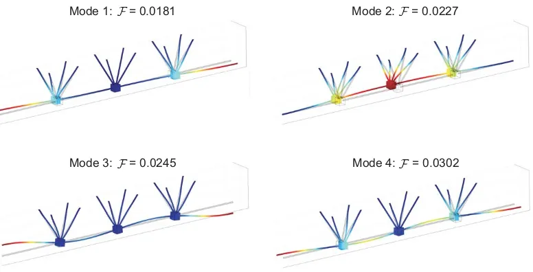
A simple analysis of the resonator structure on its own (as shown in Fig. 4), with the
assumption that the surfaces of contact with the bridge deck are fixed, gives an accurate estimate
of frequencies for a class of standing waves within the modified bridge after installation of the
periodic system of resonators. Fig. 4 also shows the four eigenmodes within the frequency
interval0 < F < 0.0303. The physical and stiffness parameters of the resonators are chosen
so that one of the eigenfrequencies of the lightweight resonator structure of Fig. 4 matches the
frequencyF = 0.0182of the standing wave of the unaltered bridge. When the two frequencies in question are sufficiently close to each other the combined structure will change its dynamic
response within the required low frequency range. Embedding of a periodic system of
Mode 1: = 0.0181 Mode 2: = 0.0227
[image:11.612.115.503.108.306.2]Mode 3: = 0.0245 Mode 4: = 0.0302
Figure 4: First four vibration modes of the resonant structure. The first mode, at normalised frequencyF = f d/v = 0.0181, is designed to eliminate the flexural vibration of the deck of the bridge. In the computationd= 4m andv =qµ/ρ = 3194m/s is the shear wave speed in the upper deck.
amplitude of vibration of the bridge deck becomes negligibly small. The proposed mechanical
system can be tuned to filter waves of desired frequencies and hence to eliminate vibration of the upper deck of the bridge within the specified frequency range.
The computation shows that for the unaltered bridge, the fundamental flexural mode
corre-sponds to the flexural vibrations of the upper deck of the bridge at a low normalised frequency
F = 0.0182. After embedding of the appropriately tuned lightweight structure of the resonators
the eigenfrequency in question has been slightly shifted, and the eigenmodes of vibration have
been dramatically changed.
In Fig. 5 we show a finite structure representing a sufficiently large section of the modified
bridge, where the left and the right boundaries of the deck of the bridge are simply supported. By analysing the vibration mode of the modified structure, we confirm that the motion of the
res-Figure 5: Modified bridge: the flexural vibration of the main body has been suppressed. The built-in resonators have taken on the vibrational motion.
onators. This gives the desired design, which eliminates the flexural vibration of the upper deck of the bridge without any major alteration of the structure in terms of mass, stiffness or
boundary conditions.
Suppression of lateral vibrations of a skyscraper. The generic method based on the
anal-ysis of waves in a periodic waveguide is now applied to such a system as a tall building, or
‘skyscraper’, composed of several copies of an elementary cell, as shown in Fig. 6 panel(2).
The displacement vector is assumed to be time-harmonic, with the radian frequencyωand the
amplitudeu, which satisfies the Lam´e system (1) and the boundary conditions (2) and (3) on
the fixed foundation and on the boundary, which is free of tractions, respectively.
We introduce a multi-scale resonator within every elementary cell, as shown in Fig. 6H, and
make use of the analysis of elastic waves within a periodic plain strain structure. The resonator
consists of a mass connected to the main frame of the elementary cell by a set of parallel thin
[image:12.612.108.503.108.325.2]( )d
2 ( )e ( )f
1
( )
g
k d
2 ( )b ( )c( )a
x
1d
x
2 [image:13.612.118.494.105.502.2]( )
h
As a design target, we would like to alter the flexural vibration modes of the original
struc-ture, within a predefined range of frequencies, to provide a set of vibration modes which do
not involve a large amplitude motion of the walls of the building. Moreover, the “thin-legged
resonators” may move and hence absorb the energy of the system. This is clearly a task of high
practical importance, which may appear in problems such as the design of earthquake-resistant structures.
The lowest translational and rotational eigenfrequencies of the thin-legged resonators can
be estimated analytically [20, 32] and the design of the resonators can be chosen to place these
eigenfrequencies within the required interval corresponding to the modes of the original
struc-ture in panel(2)of Fig. 6.
The dispersion diagram of Fig. 6G has been computed for the periodic system with the
unit cell given in Fig. 6H. This includes a group of flat bands corresponding to standing waves related to vibration of resonators within the periodic structure. We emphasize the connection
between the standing waves associated with vibrations of the thin-legged resonator and groups
or clusters of eigenmodes of the finite structure, some of which are shown in Fig. 6, panel(1).
For such frequencies, the motion of the sides of the skyscraper is negligibly small. We note
that an ad-hoc estimate of such frequencies is difficult for any realistic structure, and hence
the appropriate spectral analysis on a single unit cell is desirable, in particular, in the design
process.
The two low frequency modes of vibration of the “multi-storey” structure without built-in resonators in Fig. 6 panel(2)show that the whole macro-structure behaves like a homogenized
beam. It is noted that the building, without the system of resonators, will experience lateral
vibrations of significant amplitude and, in practical configurations, this may lead to an overall
structural failure. In Fig. 6 panel(2)we show the structure vibrating at normalised frequencies
interval containingF = 0.0225, which is the first eigenfrequency of the thin-legged resonator,
as shown in Fig. 6 panel(1).
The alteration of the vibration modes of panel (2) of Fig. 6 is achieved by introduction
of the resonators, as shown in Fig. 6 panel (1). This is fully consistent with the idea of the
modified design for the Volga Bridge discussed earlier.
We pay particular attention to clusters of normalised eigenfrequencies around the values
0.0225, 0.2254, 0.3936 and 0.4446, corresponding to standing waves. For such waves, the
exterior boundary of the elementary cell moved with very small amplitude compared to the
amplitude of vibrations of the thin-legged resonators. The four frequencies outlined above
correspond to lateral motion of the resonator, rotational mode of the resonator, localised
vi-brations of thin legs within the resonator and finally, the longitudinal translational mode of the
resonator, respectively. The associated eigenmodes are shown in Fig. 6 panel (1) where the color map corresponds to the total displacement. In Fig. 6A we have a mode dominated by
the lateral translational motion of the resonators; in Fig. 6B we observe the rotational motion
of the resonators; Fig. 6C gives an example from a large cluster of eigenmodes corresponding
to the case of localised vibrations of thin legs within the resonators. Finally, in Fig. 6D we
observe a localisation near the foundation of the structure (namely only one resonator located
at the ground level is moving, whereas the motion of the remaining structure has a
negligi-bly small amplitude). This last example shows an exponential localisation within a structured
waveguide; in this case, the skyscraper is treated as a waveguide and the embedded structure of resonators creates a stop band preventing the waves of certain frequencies from propagating
along such a waveguide. In all of these computations, the amplitude of vibration of the sides
of the large structure is very small compared to that of the individual resonators. Hence, if the
solid is subjected to an external impact, such resonance modes can be initiated and the energy
damage of the thin legs. Even though you may not be able to eat your lunch off the resonating
tables the building will survive the earthquake.
Dissipation of energy and final remarks In the re-designed bridge structure shown in Fig.
5 the waves have been channeled through the system of resonators, away from the upper deck
of the bridge. For the case of a skyscraper, inclusion of a system of resonators has led to suppression of low-frequency lateral vibrations. Although the models discussed above did not
incorporate energy dissipation, additional viscous dampers attached to the resonators can be
considered as a feasible development in a practical implementation.
The main emphasis of the paper is on the analysis of waves in a periodic system, rather
than resonance modes of a finite solid. It is shown that the analysis of the elementary cell
of the periodic waveguide provides insight and required numerical data for the design of the
full-scale engineering system. The ideas presented in this paper are generic, and the bridge problem in addition to the structural modification of a skyscraper, can be considered as possible
practical implementations. The proposed methods of analysis would equally apply to other
slender structures in civil engineering and problems of structural design.
Acknowledgments We would like to thank Professor Sir John Pendry and Professor Vladimir
Shalaev for reading the manuscript and for their support. The authors thank Dr. Anna Matveyeva
(Volgograd State University) for having given direct evidence of the structural problem of the
bridge and Professor Paglietti (University of Cagliari) for the stimulating discussions. We would
like to thank Professor R.C. McPhedran of the University of Sydney for valuable discussion and suggestions on the text of the article. The financial support of the Visiting Professorship
Pro-gram 2010 (ABM) of the Regione Autonoma della Sardegna as well as financial support of
Research Centre in Mathematics and Modelling (MB) of the University of Liverpool are
References and Notes
[1]
http://www.dailymail.co.uk/news/worldnews/article-1280919/Russian-bridge-bounces-feet-Volga-River.html
[2] http://imechanica.org/node/8280
[3] S. H. Strogatz, D. M. Abrams, A. McRobie, B. Eckhardt and E. Ott, Nature, 438, 43-44, (2005)
[4] K. Sanderson,Nature, doi:10.1038/news.2008.1311, (2008).
[5] J. H. G. McDonald,Proc. R. Soc. A,465, 10551073, (2009).
[6] L. Brillouin,Wave propagation in periodic structures: electric filters and crystal lattices, (Dover, New York, 1953).
[7] C. Kittel,Introduction to solid state physics, (J. Wiley & Sons, New York, 1953).
[8] The Photonic and Sonic Band Gap Metamaterial Bibliography, 2008 available from:
http://phys.lsu.edu/∼jdowling/pbgbib.html
[9] A. B. Movchan, N. A. Nicorovici and R. C. McPhedran, Proc. R. Soc. A,453, 1958, 643-662, (1997).
[10] C. G. Poulton, A. B. Movchan, R. C. McPhedran, N. A. Nicorovici and Y. A. Antipov,
Proc. R. Soc. A,456, 2002, 2543-2559, (2000).
[11] V. V. Zalipaev, A. B. Movchan, C. G. Poulton and R. C. McPhedran,Proc. R. Soc. A,458, 2026, 2327-2347, (2002).
[13] A. B. Movchan, N. V. Movchan, S. Guenneau and R. C. McPhedran,Proc. R. Soc. A,463, 2080, 1045-1067, (2007).
[14] S. B. Platts, N. V. Movchan, R. C. McPhedran and A. B. Movchan,Proc. R. Soc. A,458, 2024, 1887-1912, (2002).
[15] S. B. Platts, N. V. Movchan, R. C. McPhedran and A. B. Movchan,J. Eng. Mater. Technol.,
125, 1, 2-6, (2003).
[16] S. B. Platts, N. V. Movchan, R. C. McPhedran and A. B. Movchan,Proc. R. Soc. A,459, 2029, 221-240, (2003).
[17] A. B. Movchan, N. V. Movchan and R. C. Mcphedran,Proc. R. Soc. A,463, 2086, 2505-2518, (2007).
[18] R. C. McPhedran, A. B. Movchan and N. V. Movchan,Mech. Mat.,41, 4, 356-363, (2009).
[19] N. V. Movchan, R. C. McPhedran, A. B. Movchan and C. G. Poulton, Proc. R. Soc. A,
465, 2111, 3383-3400, (2009).
[20] I. S. Jones, A. B. Movchan and M. Gei,Proc. R. Soc. A, doi: 10.1098/rspa.2010.0319.
[21] J. B. Pendry,Science,285, 5434, 1687-1688, (1999)
[22] D. R. Smith,Science,308, 5721, 502-503, (2005)
[23] J. B. Pendry, D. Schurig and D. R. Smith,Science,312, 5781, 1780-1782, (2006)
[24] R. A. Shelby, D. R. Smith and S. Schultz,Science,292, 5514, 77-79, (2001)
[26] D. Schurig, J. J. Mock, B. J. Justice, S. A. Cummer, J. B. Pendry, A. F. Starr and D. R.
SmithScience,314, 5801, 977-980, (2006)
[27] T. Ergin, N. Stenger, P. Brenner, J. B. Pendry and M. Wegener,Science, 328, 5976, 337-339, (2010)
[28] A. Nicolet and F. Zolla,Science,323, 5910, 46-47, (2009)
[29] M. Brun, S. Guenneau and A. B. Movchan,Appl. Phys. Lett.,94, 6, 061903, (2009).
[30] M. Brun, S. Guenneau, A. B. Movchan and D. Bigoni,J. Mech. Phys. Solids,58, 9, 1212-1224, (2010).
[31] M. Brun, A. B. Movchan and N. V. Movchan,Cont. Mech. Therm., doi:10.1007/s00161-010-0143-z, (2010).
[32] V. Kozlov, V. Maz’ya, A. Movchan, Asymptotic Analysis of Fields in Multi-structures.