A Fully Implicit, Lower Bound, Multi-axial Solution Strategy for Direct Ratchet Boundary Evaluation: Implementation and Comparison
Alan Jappy University of Strathclyde Glasgow, United Kingdom Email: [email protected]
Donald Mackenzie University of Strathclyde Glasgow, United Kingdom Email: [email protected]
Haofeng Chen University of Strathclyde Glasgow, United Kingdom Email: [email protected]
ABSTRACT
Ensuring sufficient safety against ratcheting is a fundamental requirement in pressure vessel design. However,
determining the ratchet boundary using a full elastic plastic finite element analysis can be problematic and a number of
direct methods have been proposed to overcome difficulties associated with ratchet boundary evaluation. This paper
proposes a new lower bound ratchet analysis approach, similar to the previously proposed Hybrid method but based on
fully implicit elastic-plastic solution strategies. The method utilizes superimposed elastic stresses and modified radial
return integration to converge on the residual state throughout, resulting in one Finite Element model suitable for solving
the cyclic stresses (Stage 1) and performing the augmented limit analysis to determine the ratchet boundary (Stage 2). The
modified radial return methods for both stages of the analysis are presented, with the corresponding stress update
algorithm and resulting consistent tangent moduli. Comparisons with other direct methods for selected benchmark
problems are presented. It is shown that the proposed method evaluates a consistent lower bound estimate of the ratchet
boundary, which has not previously been clearly demonstrated for other lower bound approaches. Limitations in the
description of plastic strains and compatibility during the ratchet analysis are identified as being a cause for the
NOMENCLATURE
a Used for calculating X
b Used for calculating X
c Used for calculating X
Elastic constitutive matrix
E Elastic Modulus
f Yield function
Plastic strain normal directions
X Used to scale the constant stress for limit analysis
δ Partial derivative
Residual stress from constant load
̅ Constant cyclic residual stress
Varying cyclic residual stress
̂ Elastic cyclic stress in equilibrium with the cyclic loads at a given point in the load cycle
̂ Elastic constant stress in equilibrium with the constant load
Stress at loaded state during Stage 2
Equivalent yield stress
Equivalent yield stress used in Stage 2 limit analysis
μ Shear modulus
Total mechanical strain Elastic strain
Plastic strain
λ Lame’s constant
γ Equivalent plastic strain
Indices:
i,j,k,l,
o,p,q,r Possible values are 1,2,and 3
Superscripts:
' Deviatoric component
m Cyclic load extreme
1 INTRODUCTION
An engineering structure subject to a load cycle, in which the loads have differing frequencies and there is at least one
primary load, may experience failure through a ratcheting mechanism. This has been demonstrated analytically for a
pressurized cylinder by Bree in [1]. For a load cycle with two loads applied at different frequencies, in which the lower
frequency load may be considered to be constant,he higher frequency load is referred to as the cyclic load. If the structure
does not experience immediate collapse on initial loading, three distinct possible cyclic responses may occur on applying
the cyclic load:
1. The initial loading may or may not result in plastic strains in the structure but all subsequent loading results in
varying elastic strain only: i.e. the stress everywhere in the structure at every point on the load cycle is less than
the yield strength of the material. This response is referred to as elastic shakedown.
2. The initial loading results in plastic strain in the structure and further cyclic loading results in a fully reversed
plastic strain cycle in some parts of the structure. This is referred to as plastic shakedown.
3. The initial loading results in plastic strains in the structure and all subsequent cycles result in a net increase in
plastic strain in some parts of the structure. The net increase in plastic strain per cycle is referred to as the ratchet
mechanism, which can ultimately result in global failure of the component.
Several analysis methods have been proposed for determining or approximating the shakedown boundary, for
example [2-6]. Most of these methods predict the boundary between elastic and plastic shakedown with reasonable
accuracy, however the ratchet boundary has proved more difficult to establish. In this paper discussion is limited to direct
ratchet methods. ‘Direct’ is used here to mean those methods that are based on augmented limit analysis, however it is
recognized that other methods based on linear and non-linear programing methods are available. Of the methods
discussed here, upper bound methods, such as the Linear Matching Method [7], have been shown to be effective in
calculating the ratchet boundary. The approach presented here is aimed at furthering understanding of the requirements of
evaluating lower bounds. The proposed method uses the lower bound conditions given in [8] to develop stress update
algorithms, which allow convergence on the cyclic residual stress state, and on an estimate of the constant residual stress
state that results at the ratchet boundary due to the application of the constant load. ‘Cyclic stresses’ are the stabilized
stresses which results due to the repeated application of the cyclic loads only and which result in a close strain history. In
this method there is no need for simplification in the description of the cyclic loads and an arbitrary cyclic load case may
be used, which includes both primary and secondary stresses.
2 UPPER AND LOWER BOUND RATCHET METHODS
Direct ratchet boundary methods can be divided into two main groups: lower bound and upper bound methods. Lower
bound methods satisfy Melan’s lower bound theorem [9], which is concerned with finding a stress conditions that satisfies
equilibrium and yield at each point in the load cycle. Upper bound methods establish kinematically admissible strain
methods calculate an estimate of the cyclic stress condition that is used in an augmented limit analysis, adopting either the
upper or lower bound approach. An exception to this is the recently proposed method by Ponter [11] in which the cyclic
stresses are not found independently of the constant stresses.
The upper bound Linear Matching method (LMM) and the more recently proposed lower bound non-cyclic method,
work in a similar manner. In the LMM, the cyclic response is found by using the method proposed by Chen and Ponter in
[12]. The non-cyclic method utilizes the method presented in [13]. Both then use the cyclic stress field in a modulus
reduction analysis to find the kinematically admissible strain condition that satisfies Koiter’s upper bound theorem [10].
In these analyses, incompressibility in the strain field is maintained through assuming a Poisson’s ratio of approximately
0.5. The plastic strains however do not necessarily conform to the normality condition assumed for associative plastic
flow. This allows the structure to strain in a manner not consistent with plasticity theory. The modulus reduction
technique requires the reduced modulus from a previous iteration. If the method is to be multi-core processed it requires
the use of specialist memory types/procedures, or an additional increment to be used to store the reduced modulus in state
variable arrays. Consequently, the linear matching method is yet to be multi-core processed.
Current lower bound ratchet methods also include the Hybrid method [14], the lower bound extension to the LMM
[15], the Uniform Modified Yield (UMY) and Load Dependent Yield Modification (LDYM) methods [16] and the new
methods proposed here. The lower bound extension to the LMM [15] uses the stress fields generated by the upper bound
LMM and scales the stresses until the they satisfy the lower bound Melan theorem. Despite using a well-developed upper
bound procedure, the lower bound can take a relatively large number of iterations to achieve strict convergence The
Hybrid method generates an estimate for the cyclic stresses through the use of the direct cyclic analysis [17] currently
available in ABAQUS [18]. The stresses at the limiting points in the cycle are then read into a modified limit analysis
[14]. In the Hybrid method the modified yield surface used in the ratchet boundary evaluation is calculated based on
initial conditions. This leads to the possibility that the stresses on the ratchet boundary, as calculate by the Hybrid method,
could violate Melan’s theorem if sufficient redistribution in the stress field occurs, as demonstrated in [14]. Hybrid
method ratchet analysis is also subject to many of the same sources of instability and error as the methods presented here.
The UMY and LDYM methods [16] use the simplified description of the cyclic stresses proposed by Gokhfeld in [19].
The results for the LDYM method presented in [16] show that the LDYM method can result in ratchet boundaries above
that of the upper bound LMM, thus it is currently unclear whether these methods represent a strict lower bound.
The methods proposed here use elastic plastic finite element analysis to converge on the residual cyclic stresses. This
model is then used in an augmented limit analysis similar to that proposed by Gokhfeld in [19] and used in [14] and [16].
The modified yield strength is based on the stabilized cyclic stresses [8], as suggested in [20], to determine the ratchet
boundary. The use of stabilized cyclic stresses represents a departure from the method proposed by Gokhfled in [19] and
used in the non-cyclic method [13] and UMY and LYDM methods [16], as no simplification in the description of the
cyclic loads and stresses is applied. The methods presented here are closely linked to the Hybrid method in the use of the
stabilized cyclic stresses suggested in [20]. The modified yield strength is updated throughout the analysis, either
redistribution in the stress field. Therefore the stresses at the ratchet boundary, as identified by these methods, will satisfy
Melan’s theorem.
In the methods proposed here and in the Hybrid method, the analysis techniques make use of fully implicit solution
methods. This makes them amenable to multi-core processing using standard programing techniques, as results from
previous iterations are not required. However despite being able to multi-process the lower bound methods, shorter
solution times than the upper bound methods cannot be guaranteed for small numbers of extra cores. This is due to the
fact that non-linear analyses require additional iterations to find a stress condition which satisfy equilibrium. Under certain
conditions the Hybrid method and the proposed methods can require very small time increments in the solution procedure,
further increasing the number of iterations required over the upper bound methods.
3 PROPOSED LOWER BOUND METHOD
The proposed method is based on the following assumptions:.
Assumption 1: The load history can be decomposed into constant and cyclic parts.
Assumption 2: The cyclic loads lie within the ratchet boundary.
Assumption 3: The constant load is applied under load control.
Assumption 4: Perfect plasticity is assumed throughout.
Assumption 5: Material properties are temperature independent.
The necessary constitutive models allowing calculation of a stress condition to satisfy the conditions to prevent
ratchet and the elastic-plastic constitutive theorems have been developed in a companion paper [8]. Here the stress update
algorithms resulting from integration of the plastic strain increment over a load increment in a global Newton-Raphson
solution procedure is presented. The global Newton-Raphson solution procedure requires use of a consistent or
algorithmic tangent modulus. This gives the linearized form of the rate of change of stress with respect to the total
mechanical strain, to conserve the quadratic rate of convergence of the global Newton-Raphson scheme [21]. The
consistent tangent moduli for the numerical schemes presented here are given without derivation.
3.1 NUMERICAL SCHEME
The proposed method is based on the assumption that the load history can be decomposed into cyclic and constant
parts. This allows consideration of the cyclic loads in the absence of constant loads [19].
Stage 1 of the methods considers the cyclic loads only and, if assumption 2 is valid, finds the cyclic stresses which
resulting at the shakedown condition for cyclic loads only. Stage 1 does this by performing incremental elastic-plastic
analysis for several applications of the cyclic loads only, until the residual stresses and plastic strains converge from one
cycle to the next. Here the cyclic loads are assumed to have extremes that suitably describe the limiting points on the
Indicial notation is adopted, with the indices and their possible values given in the nomenclature section. Where
indices are repeated Einstein summation is implied.
3.2 STAGE 1 NUMERICAL SCHEME
It is assumed that the material properties are temperature independent but the method is generalized to a
multi-extreme load cycle. The necessary lower bound, conditions for shakedown are presented in [8] and the required models
summarized as:
The stresses at the point on the load cycle are given by:
̅ ̂
where is a point on the load cycle corresponds to the point on the load cycle which is unloaded w.r.t. cyclic loads i.e.:
̅
From the constitutive models formulated in [9], the residual stresses and associated strains must satisfy the condition:
̅ ( )
The equivalent von Mises stress is assumed to describe the yielding behavior such that:
| | √ ( ̅ ̂ ) ( ̅
̂ )
with, assuming associative plastic flow at the loaded state:
√
In addition, perfect plasticity is assumed throughout such that is constant, giving the equivalent plastic strain
increment:
The problem then reduces to the choice of integration scheme used to find over the increment. As it has been assumed that the plasticity is described by the von Mises yield function and that the flow is associative, it is possible to
use J2 plasticity, radial return method to fully implicitly integrate the plastic strain increment. The integration method is
defined in detail in [19]. For the case presented here, where the plasticity is assumed to be perfect, the plastic strain
The numerical scheme starts at m=1 and on converging on a residual stress condition cycles through the load cycle, using
incremental finite element analysis, until the constant residual converges:
̅ ( ) ( ) ( ̅ ) ( ) √ ( ̅ ̂ ) ( ̅ ̂ )
If then:
̅ ̅ ̅ ( ̅ ) ( ̅ ) Else (plastic): ( ̅ ̂ ) ( ̅ ) ( ̅ ) ̅ ( ̅ ) ( ̅ )
The consistent tangent modulus is:
If then check convergence on ̅
̅ ̅
Endif
If stress state converges , go to next global increment
BOX 1: STAGE 1 ALGORITHIM
3.3 STAGE 2 NUMERICALSCHEME
After the stabilized cycle has been found during Stage 1, the magnitude of constant load which can act in addition to
the cyclic loads without causing the structure to ratchet is established.
The necessary constitutive model which determines the magnitude of constant load, that can be added to the structure
without causing ratchet is formulated in [8] and summarized below, in terms of the residual stress:
( )
The equivalent von Mises stress is assumed to describe the yielding behavior such that, with superimposed elastic
stresses:
| | √ √ ( ̂ ) ( ̂ )
The yield stress is modified according to:
√ (
)( ) √
where X is given by the smallest for all of:
√
where:
where are taken from the converged solution at the end of Stage 1.
Assuming, associative plastic flow:
√
As with Stage 1, the model may be integrated with the J2 radial return method. The numerical scheme then becomes:
( )
( )
( )
X is the smallest for all of:
√
Where:
√ (
) ( ) √ ( ) ( )
√ (
̂
) (
̂
)
If then:
( ) ( )
Else (plastic):
( )
The consistent tangent modulus is then:
( ) ( √ ) | | √ ( ̅ ̂ )
where the superscript corresponds to the point on the load cyclic which gave the limiting case of X:
| ̂ | Endif
BOX 2: METHOD 1, STAGE 2 NUMERICAL SCHEME
4 COMMENTSON NUMERICAL SCHEMES
The numerical schemes are both based on the radial return method, which gives a relatively simple integration of the
plastic strain increment and results in closed form consistent tangent moduli. However, this approach has a number of
associated problems. The integration of the plastic strain increment assumes a constant normal direction throughout the
increment. In situations where there is stress redistribution, which results in a change to the stress normals, this produces a
relatively good approximation. However, if there is redistribution in which the stress normal directions change throughout
the increment, this could result in an error in the plastic strains as the ‘true’ history of the plastic strains is not captured. If
accuracy in the plastic strain directions is required then, in cases where there is redistribution in the stress state, the
magnitude of the plastic strain increment must be limited.
Analysis of the consistent tangent modulus developed for Stage 1shows that if the term
| | becomes small
then the consistent tangent modulus can become ill conditioned [21]. In such cases the global Newton-Raphson solver will
fail to converge. To overcome this problem the plastic strain increment is limited to ensure
| |
is large enough
to maintain stability in the solution. In the examples presented in Section 6 the term
This may require additional points in the load cycle to be used in addition to the limiting extremes. For example, if the
cyclic load history can be described by a single loaded extreme where
| | , then an additional point on the
load cycle must be identified where
| | . Stage 1 is then conducted using those two points as cyclic load
extremes, whichdoes not affect the final solution and allows convergence of the global Newton-Raphson solution
procedure. This particular problem arises due to the use of fixed time stepping during Stage 1 and could be eliminated by
developing a Stage 1 procedure that makes use of automatic time stepping.
The consistent tangent modulus of Stage 2 exhibits similar behavior, despite using automatic time stepping, with
| | but in this case the problem can be more pronounced as
. This might require use of
relatively small increments during the Stage 2 limit analysis. The increment size can be increased by limiting the lower
value of . In the examples presented in Section 6, the lower limit on is . By limiting the lower bound of , a slight over-estimation of the lower bound solution occurs, however if the volume of the structure
at which this limit has been applied is small compared to the failure plane, the resulting error can be assumed to be
negligible.
The consistent tangent modulus derived for Stage 2 can become ill conditioned under certain conditions of stress. In
the examples presented in Section 6 the consistent tangent modulus maintained the rate of convergence up to a point at
which a sudden decrease in solution rate was observed, see fig. 5, fig. 6 and fig. 7. In such cases the yield stress calculated
in the previous increment can be assumed to be constant through the current increment, see Section 5. This may result in a
local violation of Melan’s theorem, if the modified yield strength reduces during the increment as a result of
redistribution. If however the final increment in the analysis is small, , any violation of Melan’s theorem can be assumed negligible and the solution may be assumed to be a lowerbound.
5 CHANGE TO STAGE 2 NUMERICAL SCHEME
If the consistent tangent modulus derived for Stage 2 becomes ill conditioned, the solver may fail due to poor
convergence rate or the solution requiring increments too small to solve. To avoid this, the Stage 2 scheme can be
modified to give a more reliable solution of the ratchet boundary. The modified scheme is designed to avoid instability by
using the yield strength calculated at the start of the increment and changing the consistent tangent modulus appropriately.
This integration scheme is referred to as Method 2
( )
( )
( )
X is the smallest for all of:
√
Where:
√ (
) ( ) √ ( ) ( )
√ (
̂ ) ( ̂ )
If then:
( ) ( )
Else if (plastic):
̂
( )
The consistent tangent modulus is then:
| ̂ | Endif
BOX 3: METHOD 2, STAGE 2 NUMERICAL SCHEME
6 NUMERICAL APPLICATIONS
The stress update algorithms have been implemented in ABAQUS using the UMAT subroutine, although it is
recognized that other Finite element codes could also be used. The method developed in Section 3 is referred to as Method
1, and the method given in Section 5 is referred to as Method 2.
6.1 BREE CYLINDER
The Bree cylinder is a common bench mark for new direct shakedown and ratchet methods as it presents a case which
can be analyzed analytically. Here the axisymmetric case considered in [14] is used to investigate application of the
proposed methods. The hybrid solutions were obtained using a variation of the model proposed here and show good
agreement with the original solutions in [14], verifying the use of the residual stress state during the analysis. Note that
little redistribution of stress occurs in the Bree cylinder so little difference is expected between the proposed method and
the Hybrid method.
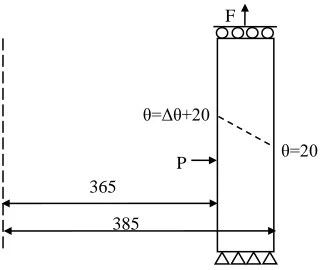
The Finite Element model dimensions are given in fig. 1. The model was created using second order reduced
integration axi-symmetric elements, with 10 elements of aspect ratio 1 through thickness. The material properties were
Young’s modulus of 184GPa, Poison’s ratio of 0.3 and yield strength 402.7MPa. The cylinder is subject to a constant
internal pressure and corresponding axial thrust simulating end cap pressure. The cyclic load is applied through a cyclic
internal temperature: the external temperature is fixed at all times to 20˚C, the temperature gradient is found by thermal
analysis with thermal conductivity of 0.035W/mm and the resultant cyclic stress is found with a thermal expansion
coefficient of 1.335e-5˚C-1. The end of the cylinder that has the end cap thrust applied is constrained to remain in plain
section.
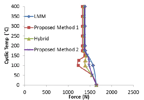
The results given in fig. 2 show that both of the proposed methods produce nominally the same results as the hybrid
method due to limited amount of redistribution in the stress field. The results also show that the proposed methods do not
overcome the deviation of the calculated boundary from the linear matching method. This is not due to the method being a
lower bound, as fig. 2 shows that the lower bound extension to the LMM can determine a lower bound closer to that given
by the upper bound LMM.
The resulst presented in fig 2 indicate that there may be a fundamental limitation to the vector summation type of
direct ratchet methods such as the hybrid method and the methods presented here. In the Bree cylinder analysis, all of the
methods were able to find the ratchet condition; that is, the equivalent stress in the cylinder is equal to yield at some point
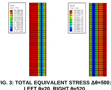
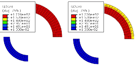
which gives the equivalent stress in the structure for Δθ=500 at the θ=20 and θ=520 points on the load cycle. It is seen
that the inner portion of the cylinder is limited by the θ=20 load case and the outer portion of the cylinder is limited by the θ=520 load case. This indicates that no further improvement can be achieved on the ratchet boundary with the current
vector type lower bound methods, and the approach must be fundamentally changed to achieve better agreement with the
LMM.
6.2 PRESSURISED TWO BAR STRUCTURE
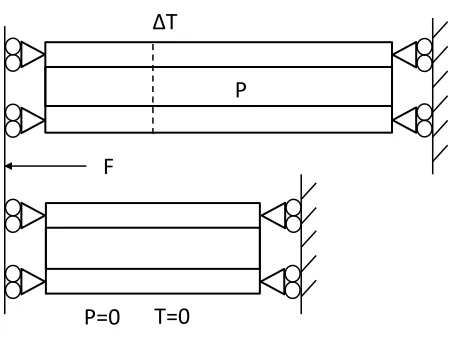
The pressurized bar structure shown below in fig. 4, modified from [22] and analyzed in [14], is investigated here to
obtain further insight into the deviation of the ratchet boundary prediction from that of the linear matching method. . Bar 1
has an internal radius of 2.00mm and an external radius of 2.68mm. Bar 2 has an internal radius of 2.00mm and an
external radius of 3.22mm. Bar 2 is twice the length of bar 1 and both have the same material properties: Young’s
modulus of 210GPa , Poisson’s ratio of 0.3, yield strength of 200MPa and a thermal expansion coefficient of 1.17x10⁻⁵˚C
-1
. The ends of the cylinders are constrained to remain in plane section at all times. The model was defined in 3D with
second order reduced integration elements, with six elements through the thickness of bar 2 and 3 through the thickness of
bar 1.
The load cycle is described by a constant load which consists of internal pressure applied to bar 2 without a
corresponding end cap pressure and an axial force which is distributed between both bars by a plane section constraint.
The cyclic load is applied as a varying temperature, above the reference temperature, in bar 2, with the temperature being
uniform throughout the bar. Bar 1 remains at the reference temperature at all times. Pressure and axial force are
considered for three separate conditions : where the force F in Newtons divided by the pressure P in MPa is F/P=10,
15 and 20. This is done to test the proposed method under varying extents of multi-axial stress conditions. The ratchet
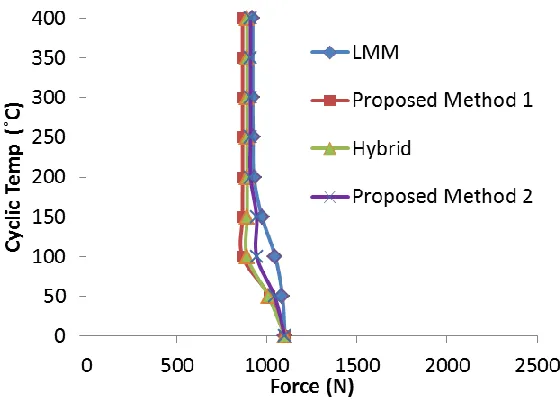
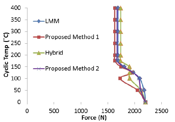
boundary as determined by the proposed method, the hybrid method and the LMM are given in figs. 5 to 7.
The results show that the proposed method produces different results to the Hybrid method for the varying degrees of
multi-axial stress condition. In most of the points considered Method 1 produces results below that of the hybrid method.
This can be attributed to the consistent tangent modulus becoming ill conditioned, resulting in a premature failure of the
ratchet solution. Method 2 produces a boundary more consistent with the upper bound linear matching method in all of the
conditions analyzed. Both of the proposed methods avoid the possibility of the non-conservative results seen in the hybrid
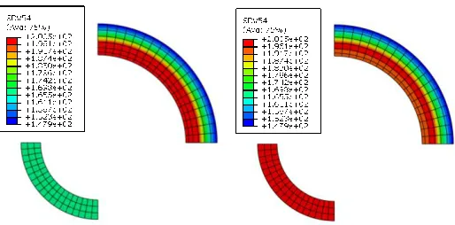
method. For F/P=20 at a cyclic temperature above approximately 140˚C this can be attributed to the hybrid method not
considering the effective weakening of the structure caused by stress redistribution, see fig. 8.
7 DISCUSSION
The proposed lower bound direct ratchet method solution schemes account for stress redistribution through
modification of the yield stress when the constant load is applied. The method is therefore able to account for increased
strength when the stress redistribution is beneficial and reduced strength when the stress distribution is detrimental,
example components at load F/P=20 and Δθ=150˚C evaluated by the Hybrid method and the proposed method. The
reduced yield strength shown for the proposed method ensures that the calculated ratchet boundary is conservative,
whereas the Hybrid method does not simulate this response.
Two plastic strain increment integration strategies have been implemented in the method. Both give good agreement
with the hybrid method for the Bree cylinder, due to the limited stress redistribution occurring in that example. When
more extensive stress redistribution occurs in problems such as the plate with hole in [8] and the pressurized two bar
problem, numerical instability can occur during Stage 2 limit analysis of Method 1, resulting in premature termination of
the analysis. This instability may be due to competing limiting stress conditions within the solution. In the Bree cylinder
example, a single load case limits the response at each point in the structure and a consistent cyclic load defines the
consistent tangent modulus, leading to a relatively stable solution. However, in the pressurized two bar problem the
structure can develop a stress field in which more than one extreme point in the load cycle must be limited to the yield
stress. Fig 9 shows the total equivalent stress in the two-bar structure members at F/P=15 with Δθ=0˚C and Δθ=150˚C. In the latter case, the stress distribution could result in a rapidly changing modulus causing instability. Other sources of
instability could also contribute to premature solver failure. Method 2 addresses this problem by updating the modified
yield surface using converged solutions from the previous increment, resulting in a relatively stable solution method.
However, Method 2 still demonstrates considerable deviation from the upper bound ratchet method solutions. Therefore,
whilst the ratchet boundary given by Methods 1 and 2 will be conservative it could be excessively conservative under
multi-axial stress conditions.
The example problems considered show that the proposed lower bound methods are in limited agreement with LMM
upper bound solutions. However, the lower bound approximation of the LMM demonstrates that it should be possible to
establish residual stress fields closer to the upper bound solution that satisfy Melan’s theorem. Possible reasons for the
discrepancies in the proposed method are compatibility errors in the solution procedure and inconsistent evaluation of
plastic strain direction..
The stress distribution in the pressurized bar problem at F/P=20 is predominantly uniaxial and the Method 2 results
show reasonable agreement with the upper bound LMM except at the point at Δθ=50˚C. The cyclic temperature produces
a stress in bar 1 causing yield at cyclic temperature of approximately 84˚C and reverse plasticity at 168˚C. Beyond 168˚C,
bar 1 becomes perfectly flexible to additional strain caused by the thermal load in bar 2. Above 168˚C the Method 2
results are independent of increasing temperature and exhibit good agreement with the LMM solution (this behavior is
also observed for F/p=10 and 15). Below 168°C, the difference between the Method 2 and LMM solutions may be due to
incompatibility between the two bars and within individual bars.
The Method 2 Bree cylinder results are different to the LMM for cyclic temperatures considerably below the first
yield and reverse plasticity loads. At these points compatibility issues caused by cyclic solutions should not occur.
However, the plane section constraint applied to the free end of the cylinder may significantly influence the local stress
state resulting from a given plastic strain direction. The plastic strain which would result in the actual structure would be
̂
| ̂ |
The difference in normal directions may have a significant impact on the axial strain in the parts of the structure that
yield, which would then affect the plane section constraint and the resulting redistribution of stress. A similar situation
may occur in bar 2 of the pressurized two bar structure, giving a possible reason for the greater deviation of the results in
the elastic shakedown region for F/P=10 and F/P =15.
Further work is required to better understand the effect of compatibility and plastic strain directions during the Stage 2
limit analysis. Whilst carrying over the plastic strains from Stage 1 is relatively simple, using the actual plastic strain
direction would make identifying a limiting case more difficult as the direction of plastic strain would be different for
different cyclic loads.
8 CONCLUSIONS
The proposed lower bound direct ratchet methods account for stress in a cyclically loaded structure when a constant load
is applied. This approach achieves closer agreement with the LMM upper bound solution than the lower bound Hybrid
method. This feature also removes the possibility of evaluating a non-conservative estimate of the ratchet boundary.
The example problems presented identify two possible limitations on vector summation type lower bound ratchet
methods: loss of plastic strains between the cyclic and ratchet stages of the analysis resulting in compatibility problems
and the calculation of the plastic strain direction based on the constant load only.
To increase the reliability of the proposed lower bound ratchet methods, further work is required to fully understand
the impact of compatibility and plastic strain directions during Stage 2 of the solution procedure.
ACKNOWLEDGEMENTS
The authors would like to acknowledge the contributions of Mr James Ure, University of Strathclyde Glasgow for his
lower bound LMM results and also the contributions of Mr Michael Lytwyn, University of Strathclyde Glasgow for his
upper bound LMM results.
REFERENCES
[1] Bree, J., 1967, “Elasto-plastic behaviour of thin tubes subjected to internal pressure and intermittent heat fluxes with
application to fast reactor fuel elements,” J. Strain. Analysis, 2, pp.226-238.
[2] Chen, H.F., 2010, “Lower and Upper Bound Shakedown Analysis of structures With Temperature-Dependent Yield
Stress,” Journal of Pressure Vessel Technology, pp.132, 1-8
[3] Staat, M., Heitzer, M., 2001, “LISA a European Project for FEM-based Limit and Shakedown Analysis,” Nuclear
[4] Muscat, M., Mackenzie, D. and Hamilton, R., 2003, “Evaluating shakedown by non-linear static analysis,”
Computers and Structures, 81, pp.1727-1737.
[5] Abdalla, H.F., Megahed, M.M., Younan, M.Y.A., 2007, “A Simplified Technique for Shakedown Limit Load
Determination,” Nuclear Engineering and Design, 237, pp.1231-1240.
[6] Mackenzie D, Boyle J T, Hamilton R., 2000, “The Elastic Compensation Method for Limit and Shakedown Analysis:
a Review”, The J. Strain Analysis for Engineering Design, 35 (3), pp.171-188.
[7] Chen, H.F., 2010, “A Direct Method on the Evaluation of Ratchet Limit,” J. Pressure Vessel Technology, 132,
041202
[8] Jappy, A., Mackenzie, D., Chen, H., 2012, “A Fully Implicit, Lower Bound, Multi-axial Solution Strategy for Direct
Ratchet Boundary Evaluation: Theoretical Development,” PVP2012-78314, July 15-19, Toronto, Ontario, CANADA
[9] Melan, E., 1936, “Theorie Statisch Unbestimmter Systeme aus Ideal-Plastischem Bastoff,” Sitzungsberichte der
Akademie der Wissenschaft. Wien, Abtiia, 145, pp.195–218.
[10] Koiter, W.T., 1960, “General theorems for elastic plastic solids,” Progress in solid mechanics, J.N. Sneddon and R.
Hill, eds. North Holland, Amsterdam, 1, pp.167-221.
[11] Weichert, D., Ponter A., 2009, Limit States of Materials and Structures, Springer Science+Business Media
[12] Chen, H., Ponter, A., 2001, “A method for the evaluation of a ratchet limit and the amplitude of plastic strain for
bodies subjected to cyclic loading,” Eur. J. Mech. A/Solilds, 20, pp.555–571.
[13] Adibi-Asi, R., Reinhardt, W., 2010, Ratchet Boundary Determination Using a Noncyclic Method. Trans. ASME, J.
Pressure Vessel Technology; 132, 021201-021201-9
[14] Martin, M., 2009, “A hybrid procedure for ratchet boundary prediction,” Pressure Vessels and Piping, Prague, Czech
Republic
[15] Ure, J., Chen, H., Li, T., Chen, W., Tipping, D., Mackenzie, D., 2011, “A Direct Method for the Evaluation of Lower
and Upper Bound Ratchet Limits,” International Conference on the Mechanical Behaviour of Materials. June 5th-9th,
Lake Como, Italy
[16] Abou-Hanna, J., McGreevy, T. E., 2011, “A simplified ratchet limit analysis using modified yield surface,” Int. J. of
Pressure Vessel and Piping, 88, 11-18
[17] Nguyen-Tajan, et al. 2003, “Determination of the stabilized response of a structure undergoing cyclic
thermal-mechanical loads by a direct cyclic method,” Abaqus Users' Conference Proceedings
[18] 2010, Abaqus 6.10, SIMULIA
[19] Gokhfeld, D.A. and Cherniavsky , O.F., 1980, Limit Analysis of Structures at Thermal Cycling, Sijthoff &
Noordhoff
[20] Polizzotto, C., 1993, “A Study on Plastic Shakedown of Structures: Part II- Theorems,” Trans. ASME, J. Applied
Mechanics, 60, pp.20-25.
[21] Simo, J. C, Hughes, T.J.R, 2000, Computational Inelasticity, Springer-Verlag
[22] Abdalla, H.F, Megahed, M.M., Younan, M.Y.A., 2007, “A Simplified Technique for Shakedown Limit Load
List of Figures
FIG. 1: BREE CYLINDER WITH CAPPED END: DIMENSIONS
FIG. 2: RATCHET BOUNDARY: BREE
FIG. 3: TOTAL EQUIVALENT STRESS Δθ=500:LEFT θ=20, RIGHT θ=520
FIG. 4: CONSTRAINTS FOR PRESSURIZED TWO BAR STRUCTURE
FIG. 5: RATCHET BOUNDARY F/P=10
FIG. 6: RACHET BOUNDARY F/P=15
FIG. 7: RATCHET BOUNDARY F/P=20
FIG. 8: MODIFIED YIELD STRENGTH F/P=20 Δθ=150˚C LEFT: HYBRID, RIGHT: PROPOSED METHODS
θ=Δθ+20
θ=20 P
F
[image:19.612.78.238.93.228.2]365 385
P
F
ΔT
P=0
T=0
[image:22.612.37.262.88.258.2]
FIG. 8: MODIFIED YIELD STRENGTH F/P=20 Δθ=150˚C