PERFORMANCE ANALYSIS OF AIR SOURCE HEAT PUMPS USING DETAILED
SIMULATIONS AND COMPARISON TO FIELD TRIAL DATA
N J Kelly
1, J Cockroft
2, S Gauri
21
Energy Systems Research Unit, Mechanical Engineering, University of Strathclyde, Glasgow,
UK
2
Scottish Energy Systems Group, University of Strathclyde, Glasgow, UK
ABSTRACT
The take-up of heat pump technologies in the UK domestic sector has lagged far behind other countries in Europe and North America due primarily to the ready availability of cheap natural gas; this has led to the predominance of gas central heating systems in UK housing. However, with recent gas price volatility along with the depletion of the UK’s natural gas reserves interest in heat pump technology, particularly Air source heat pumps (ASHPs) is growing as they have the potential to be a direct, low-carbon replacement for existing gas boiler systems. However, to-date there have been few detailed, simulation-based performance studies of ASHP systems.
In this paper a robust, dynamic simulation model of an ASHP device is described. The ASHP model has been integrated into a whole-building model and used to analyse the performance of a retro-fit domestic ASHP heating system. The simulation results were then compared to field trial data.
INTRODUCTION
The UK’s international greenhouse gas reduction commitments and national greenhouse gas reduction targets are driving increasingly stringent building regulations such as net “zero carbon” homes (this excludes appliance use) in England and Wales by 2016 (DCLG, 2007) and a target for whole-life zero-carbon homes in Scotland by 2030 (Sullivan, 2007) and an expectation for an 80% cut in CO2 emissions by 2050 (DECC, 2009a). In parallel, increasing fuel price instability (BBC, 2008), particularly in the price of natural gas is forcing a re-think in the provision of space and water heating in the domestic sector. Close to 80% of the UK’s domestic water and space heating demands are met using gas boilers (Shorrock and Uttley, 2008) and it is highly unlikely that the UK’s emissions reduction targets could be achieved if this state-of-affairs persists. Hence, there is increasing interest in meeting the heat and power demands of buildings using low or zero-carbon (LZC) technologies such as biomass boilers, micro-renewables and heat
pumps. Heat pumps are (belatedly) attracting increasing interest in the UK in that they complement major changes occurring at the larger scale in electricity production: the UK is currently embarking on the development of huge quantities of onshore and offshore wind generation. Heat pumps offer the potential for low or zero carbon heating as the carbon content of grid electricity reduces into the future. Air source heat pumps (ASHPs) are of particular interest in that they have the potential to directly replace gas boilers in existing buildings and can operate in high-density housing (e.g. flats and terraced dwellings). High density housing comprises approximately 40% of the UK housing stock (Shorrock and Utley, ibid) and so the potential for retro-fitting of the technology is significant.
Whilst there is an extensive literature on the performance of ground source heat pumps in the domestic sector (e.g. Healy and Ugursal [1997], Kummert and Bernier [2008] in Canada; and Underwood and Spitler [2007], Jenkins et. al. [2009a] in the UK) the literature on ASHP performance is far more sparse. Most modelling work focuses on specific aspects of device performance (e.g. Lui et al [2003], Yao [2004]) rather than integrated performance. In those performance studies that exist, Cockroft and Kelly (2006) used a low-resolution model to determine that in a UK context ASHPs could achieve significant carbon savings in comparison to the domestic heating technologies, including condensing gas boilers. Jenkins et al. (2009b) looked at the carbon savings potential of ASHP in office buildings and concluded that the technology did not guarantee emissions savings under all circumstances; this study used a performance map model of the ASHP and hourly predictions of heating and cooling from a simulation tool.
complete 1-minute
FIELD
It was ag heat pum Energy p village of properties provided project. T effectiven needs of specifical outdated fired hea Westfield space he running f in additio heating sy run often of the ke exercise through a this comp condensin
A total of an ASHP constructi A typical shown in two-leaf, (the cav insulation and wet comprised felt and p trusses. T timber, w floor. The ASH directly insulated dwelling. performan these fiel load only supplied coil, whi
1 In the UK more than 1
with an ASH time steps.
TRIAL DE
gainst a back mp technolog lc. commissio f Westfield s owned by practical su The objective ness of ASHP
the Councils’ lly those ele direct electri ating systems d contribute t eating: with from early Sep
on to being c ystems were r n leaving tena ey objectives was to inv a switch to AS pared to the ng gas boiler.
f 10 houses in P system; the ion (Table 1).
l terraced hou n Figure 1. Th
100mm brick ities having n upgrade); th
t-plastered i d concrete til plywood skin The floors in with a ventilat
HP heating sy feeding hot pipes runnin The ASHP u nce of 3.0 wi ld trials the A y, with the h
using an exis ch heated a h
K the definition 10% of its income
HP heating sys
ETAILS
kground of in gies that Scot
oned a field tr (55.9 N, 3.7 y West Loth
upport and s of this trial w Ps in meeting ’ existing stoc ements of the ic heating an s. The climat to a significa the heating ptember until
carbon intens reputedly extr ants in fuel po
of the field t vestigate pot SHPs for spac
alternative re
n the village w ese were all o
use encounte he dwelling’s k, with a 120m
been previo he walls were internally. T les lying on t
, which is sup n the dwellin
ed crawl spac
ystem compri water radiat ng under the used had a nom
ith a rated ca ASHP served hot water for sting 3kW dir hot water sto
of fuel poverty i e on fuel bills.
tem, which is
ncreasing inter ttish and So rial of ASHPs W) using ten hian Council,
sponsorship o was to determi
g the space h ck of social h e stock relia nd inefficient
te and locati ant requireme g season typ
the end of Ma sive, the dwe
remely expens overty1. Henc trial and simu tential expen ce heating an etro-fit option
were retro-fitte of similar siz
red in the stu external walls mm insulated ously filled rendered exte The pitched top of a bitum
pported by w ng were susp ce under the g
ised an ASH ors (figure 2 e flooring of
minal coeffici apacity of 8 k d the space h r each house
rect electric h orage tank; fo
is a household s
run at rest in uthern in the nanted , who of the ine the heating houses, ant on t coal-ion of ent for pically ay. So, llings’ sive to ce, one ulation nditure nd how n of a
ed with ze and udy is s were cavity in an ernally roof minous wooded pended ground P unit 2) via f each ient of kW. In heating being heating or cost pending re H sh dw te ea lo a T re li co al d an A w h re ph w • m su p re m
easons this wa However, it sh hould be capa welling. The r emperature of ach radiator ocated in the h thermostatic r
The ASHP wa eading from a iving room of ould be select lso free to s evice, select T nd to occupy t
Figure 2 ab
A radio freq wireless senso
ouse, with o ecovered tran hone network were as follow
the electric measured usin upply to the ower consum ecorded curre mains voltage)
Figure
as not integra hould be note able of meetin radiators were f the ASHP de (except a b hall of each d radiator valve
as controlled a wall mounte
each dwelling ted by the occ elect the ope TRV settings the property a
bbreviated sch radiator
quency (R.F.) ors/transmitter one central re nsmitted wirel
k. The perform s:
cal consumpti ng a current heat pump ( mption was d ent draw in a
;
1: terraced dw
ated with the A ed that the de ng the hot wat e sized for the evice of 55oC. by-pass radia dwelling) was e (TRV).
based on th ed thermostat g. The set poin cupant. The o eration time , open doors as they normal
ematic of the system.
) telemetry rs, was insta eceiver/logger lessly via the mance param
on of each h transformer (the instantan derived by m amps by the wellings at We
ASHP system evice installed ter load of the e nominal flow The flow into ator, typically s controlled by
he temperature located in the nt temperature ccupants were of the ASHP and windows lly would.
ASHP and
system, with alled in each r. Data wa
GSM mobile eters recorded
• the to measured the perfor
• the h
using a h pulse outp • outsid recorded. Temperat (typically house. Th electrical current c transmiss 2008, and dropped interrupti total of 9 8 houses and early to the resu
SIMUL
As the m season, a 2001) wa 1. The ES of the dw the heat p in Figure a thermal were ide building flow mod leakage r test of t changes p varying e also enab Heat gain on survey trials and consumpt estimation analysis o despite t condition auxiliary heating e of their o simulatio
The heati network.
otal electrical d along with v
rmance of the
eat output of heat meter wi put per kWh;
de air tempera
tures were y the living ro
he transmissio current clam clamp transm sion interval.
d stopped in J out of the ons due to eq 1 days of data over this tim y summer wea ults of the sim
LATION MO
monitored data an integrated E
as developed SP-r model co welling along w
pump and heat 2. Each indiv l zone and the entical to tho model was a del that was rate as that de the actual b per hour); in exchange of a bled inter-room
ns for the build ys of user beha d through anal
tion of the n of equipm of the electrica the heat pum ns, a few oc
heating dev enabling them old coal fire; ns.
ing system wa In such a net
consumption voltage (volta heat pump sy
f the heat pu ith integrating
ature and rela
measured a oom, hall and on interval fo mps was set a mitters were s Monitoring s July 2008. Tw study and quipment mal a was collecte me period cove
ather; this dat mulation exerc
ODEL
a only covere ESP-r simulat for the buildi omprised a det with an explic ting distributi vidual room w e construction ose in the ac also augmente calibrated to etermined fro uilding (appr addition to ca air with the e m air flows to
ding model w aviour conduc lysis of the to dwelling; th ment heat gai al demand dat mp providing ccupants insis vices such as m to “simulate
; this was ac
as modelled u twork all of t
in each hous age variations ystem);
ump was me g electronics
ative humidity
at three loc a bedroom) in r all sensors at 2.5 minutes set at a 30 s
started in Feb wo of the prop there were lfunctions so ed for the rem
ering winter, ta is compare cise.
ed part of a h tion model (C ing shown in tailed represen cit representat on system as was modelled ns used in the ctual building ed with a zon
give the sam om the blowe
roximately 0 alculating the exterior, this be calculated
were estimated cted during th otal electrical his helped i ins. Note th ta also reveale
adequate co sted on emp s radiant ele ” the heating ccounted for
using an ESP-r the heating sy
se was affect asured and a y were cations n each except s. The second bruary perties some that a maining spring d later heating Clarke, figure ntation tion of shown d using model g. The nal air me air r door 0.5 air e time-model . d based he field power in the at the ed that omfort loying ectrical effect in the r plant ystems co m th gi A re E an m el it pl el th o ou in on co co A th ad u fo (2 b un h em T ap te co co T v a
[image:3.595.309.503.156.297.2]omponents ( modelled expl he basic heati iven by Hense
Figure 3 diag
A detailed AS eported here ESP-r building nalysis persp model was to
lectrical dema ts explicit inte lant, and co lements that n hat couple the f a building utput (hot wa nterest includ n/off cycli ompensation, onsumption Accurately det he dynamics dequately mo sed in this ollowed the 2009), where ox” approach nderlying ph owever, its mpirically der The modelling pplied succe echnologies ogeneration ogeneration (B
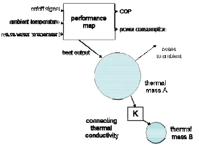
The ASHP m olumes (Figur series of inpu
(radiators, pi licitly. A com ing system m en (1986) and
grammatic rep mod
SHP model w that could b g and plant m pective the m
o accurately and and therm eraction the bu
ontrol system needed to be s
e ASHP devic simulation m ater), and hea ded the device ing, defros
etc.), perfo and result termining thes of the devic odelled. The r
modelling st template desc the device i in that the m hysical chara performance rived expressi g approach essfully to such as and internal Beausoleil-Mo model structur re 3). The fir uts and outpu
iping, valves mprehensive d models used in d Clarke (2001
presentation o del.
was developed e fully integr model. From a main requirem
predict the mal output of t
uilding’s enve ms. Thus, t simulated were
ce to the othe model, specifi
at losses. Oth e’s operation st status, ormance effic
ting carbon se parameters ce’s heat ex representation tudy (Figure cribed by Fe is modelled u model structur acteristics of was approx ions. described he other dome Stirling combustion orrison and K
re comprises rst single volu uts linked by a
s, etc.) were description o n this work i 1).
of the ASHP
d for the work rated into the a performance ment for thi
time-varying the device and elope, therma the importan e the variable er constituent cally the hea her outputs o al status (e.g temperature ciencies, fue n emissions s required tha changes were n of the ASHP 3) therefore erguson et al using a “grey re reflected the f the device ximated using
map (a series of parametric equations linking the inputs of the model to the outputs). In this case the COP of the ASHP is represented as a 2nd-order polynomial function of the heating system return water temperature and the external ambient temperature difference.
)
(
T
returnT
ambientf
COP
=
−
(1)The performance map was augmented with algorithms to calculate the defrost status of the device and to modulate the return water temperature set point based on outside temperature. The predicted heat output from the performance map volume was passed to a lumped-capacitance thermal model, featuring two thermal control volumes; these were added to enable the transient thermal performance of the device and coupled heat exchange equipment (condenser and evaporator heat exchangers) to be adequately modelled. The general form of the energy balance for these elements is as follows.
)
(
1Q
t
dt
dT
c
M
i nj ji
i
=
∑
=&
(2)
Where Miciis the thermal capacity of volume i (J/K); T is its temperature (oC) and Q(t)1…n are individual heat fluxes at time t e.g. heat loss from the volume to environment; heat flux from another volume; heat lost to coolant, etc.
CALIBRATION
The ASHP model functional block was calibrated using data from independent laboratory performance tests conducted on the ASHP device conducted by BRE Ltd.; these gave performance characteristics over a broad range of condenser and evaporator temperatures. The lumped capacitance elements of the model were calibrated using an iterative parametric identification technique described by Ferguson (2009) with high resolution start-up data from the field trial data.
METHODOLOGY
The simulation of the ASHP system comprised several stages of work 1) the model predictions were compared against the field trial data 2) the model was simulated over a full year and performance data extracted 3) the performance of the ASHP was compared to an annual simulation of a gas boiler system.
Simulations were run over a 1-year time period at a resolution of 1-minute intervals. This resolution was employed to adequately capture the dynamic performance of the heating system featuring the heat pump, particularly with regards to the operation of the control system and operations such as defrost and on/off cycling. Other researchers notably Hawkes and
[image:4.595.308.530.177.344.2]Leach (2007) have indicated that such high resolution modelling is required in order to adequately characterise performance. Finally, as no long-term climate data existed for the Westfield site, simulations were run with an equivalent Scottish climate data set that was representative of the field trial location.
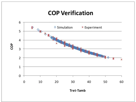
Figure 4 calibrated COP characteristics of the ASHP device.
VERIFICATION WITH FIELD TRIAL
DATA
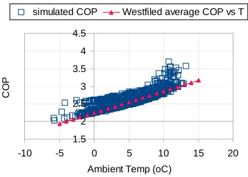
Before simulating performance of the ASHP system when integrated into the Westfield dwelling, the integrated model’s predictions were compared to the performance data from the field trial. Figure 5a shows the predictions of COP vs ambient air temperature from the simulation of the ASHP device against the average COP vs ambient air relationship emerging from the field trials; this average relationship was derived from the measured COP values from eight of the monitored houses will be used as representing typical ASHP performance in these types of houses. This averaged relationship represents typical operating conditions for the monitored properties under varying conditions of occupancy. It offers a suitable comparison metric for the results of the simulation model in that the climate and assumed occupancy for the simulation model will differ from the exact conditions experienced during the field trials. A temporal comparison of simulation and monitored results would therefore not be appropriate under these circumstances. Comparing the simulation results to the averaged COP relationship allows a comparison of operating characteristics rather than temporal match to be undertaken.
Comparing the simulation output to the field trial COP relationship (Figure 5a) it is evident that the scatter in the ASHP model output is predominantly above the average COP line: these points are indicative of the dynamic nature of the model and represent periods
0 1 2 3 4 5 6
0 10 20 30 40 50 60
CO
P
Tret‐Tamb
COP
Verification
when the heating system and building are warming up and where the resulting low heating system flow and return temperatures produce a temporarily high COP. However, the highest density of points is close to the average performance line; corresponding with periods in which the heat pump was operating with the return water temperature close to the set point (45oC).
However, the simulation results clearly diverge from the monitored data at higher ambient air temperatures. Subsequent investigation revealed that the temperature compensation facility on the heat pump had not been enabled on the Westfield installations due to an installer error. Consequently, a second annual simulation was conducted with the temperature compensation disabled on the ASHP model. Figure 5b shows the comparison for this simulation and shows that the highest density of simulated results lie on or close to the average COP characteristic from the field trial; this demonstrates that the ASHP device in the ESP-r model operating in under similar conditions to those experienced at Westfield.
RESULTS ANALYSIS
[image:5.595.314.494.126.255.2]The annual simulation data (with temperature compensation enabled) was further analysed to give an indication of likely annual ASHP performance when retro-fitted into the Westfield dwelling. Figure 6 is a typical example of the high resolution data extracted from the simulations and shows the living room air temperature, heat pump heat output, power consumption and return water temperature during part of a typical winter day.
Figure 5a predicted COP vs Westfield average.
Figure 5b predicted COP (no temperature compensation) vs Westfield average.
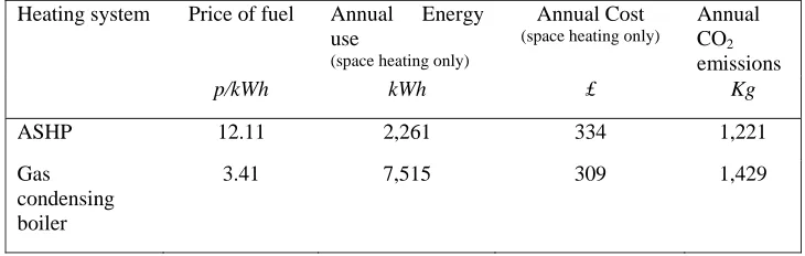
Annual performance metrics were extracted from the high resolution data: the average annual COP for the device was approximately 2.7. The estimated energy annual electricity consumption for the ASHP was 2261 kWh (8.14 GJ).
[image:5.595.315.522.493.624.2]A further simulation was undertaken where the ASHP heating system model was replaced with a model of a gas condensing boiler heating system. Other than the re-sizing of the radiator components to account for a higher supply temperature of 75oC, the system details are the same as those for the ASHP-based system shown in Figure 2. The nominal efficiency of the boiler device model used was 91%, which is typical of a modern boiler being installed in the UK at present. Note that the simulated system efficiency was lower due to parasitic losses.
Figure 6 typical winter day results from the simulation.
Analysis of the simulation results indicated an annual gas consumption of 7515 kWh (27.05 GJ or 691.8 m3) to meet the dwelling space heating load.
Table 2 shows the annual energy consumptions, cost, and CO2 emissions emerging from the simulations for the simulated house heated using the ASHP (with
1.5 2 2.5 3 3.5 4 4.5
-10 -5 0 5 10 15 20
Ambient Temp (oC)
CO
P
simulated COP Westfield average COP vs T
1.5 2 2.5 3 3.5 4 4.5
-10 -5 0 5 10 15 20
Ambient Temp (oC)
CO
P
simulated COP Westfiled average COP vs T
0 1000 2000 3000 4000 5000 6000 7000 8000
1.2 1.4 1.6
Time (days)
Pow
e
r (W)
0 10 20 30 40 50 60
Temper
at
ur
e (
o
C
)
[image:5.595.75.254.503.642.2]weather compensation enabled), and the alternative retro-fit option of a condensing gas boiler. Note that CO2 emissions are based on carbon intensities of 0.19 kg/KWh for natural gas and 0.54 kg/KWh for grid electricity (DEFRA, 2009).
The results indicate that an ASHP installation would
produce approximately 15% less CO2 than a
condensing gas boiler installation. This reduction would be greater if grid decarbonisation occurs, however it should be noted that the trend in UK grid electricity carbon intensity has been upwards in recent years rising from 0.52 kg/kWh in 2001 to the current value of 0.54 (Carbon Trust, 2009).
With current UK gas and electricity prices, annual space heating costs using the ASHP are approximately 8% higher than a gas condensing boiler system (£334 in comparison to £309). In this case the ASHP system could only become cost competitive if the electricity/gas price ratio dropped below 3.32 compared to the current level of 3.55 (DECC, 2009b).
It should be noted that both systems would be significantly less expensive to run than the direct electric and coal fired systems replaced prior to the study. For example, direct electric heating would result in an annual space heating bill of approximately £660, whilst space heating using a coal fired room heater would cost approximately £530 per year, assuming a device efficiency of 63% (Hens et al., 2001).
CONCLUSIONS
A combination of simulation and field trial data has been used to assess the annual performance of a domestic ASHP heating system when integrated into social housing in Westfield, Scotland.
A detailed ASHP device model has been developed on the ESP-r platform based on the work of Ferguson et al. (2009) and calibrated using laboratory data. This model was integrated into a whole building ESP-r model of one of the Westfield dwellings.
The model was compared to data emerging from the Westfield field trial; the simulation model was seen to suitably replicate the ASHP operating conditions observed in the field trial.
Comparison of simulation results with field trial data indicated some installation problems with the ASHP device in that temperature compensation has not been activated. Additionally there was some evidence that some householders were employing secondary heating – despite the ASHP installation maintaining adequate comfort conditions.
Simulations were undertaken to estimate the annual energy performance of the ASHP device and an equivalent gas condensing boiler system when retro-fitted into a typical Westfield dwelling. These indicated that:
• The ASHP offered approx. 15% carbon savings in comparison to a gas condensing boiler system using 2009 UK CO2 emissions coefficients for electricity and gas.
• ASHP running costs were 8% higher using 2009 UK average electricity and fuel prices than a standard gas condensing boiler system.
FURTHER WORK
The work reported in this paper represents the initial stages of the detailed modelling of domestic ASHPs in the UK. A range of additional simulations are being undertaken as part of several follow-on projects to gauge the performance of ASHP devices in a broader range of dwelling types and with respect to future more rigorous insulation building standards.
ACKNOWLEDGEMENTS
The authors would like to thank Scottish and Southern Energy Ltd. who funded the field trial and performance study; and Mr Chris Chisman of TEV Ltd. who provided heat pump technical data.
REFERENCES
BBC (2008), Record Rise for British Gas Bills, On-line News Article 30 July, Available from: http://bbc.news.co.uk/1/hi/business/753389.stm
(Accessed 17/12/2009)
Beausoleil-Morrison I and Kelly N J [eds] (2007),
Specifications for Modelling Fuel Cell and Combustion-Based Residential Cogeneration Devices
Within Whole Building Simulation Tools. IEA ECBCS
Annex 42 Report, HMQR Canada, Ottawa. Available from: http://www.ecbcs.org.annexes/annex42.htm#p
Clarke J A (2001), Energy Simulation in Building
Design, 2nd Edition, Butterworth-Heinemann, Oxford.
Cockroft J and Kelly N J (2006), ‘A Comparative Assessment of Future Heat and Power Sources for the
UK Domestic Sector’, Energy Conversion and
Management, 47 (15), 2349-2360.
Department for Communities and Local Government [DCLG] (2007), Building a Greener Future: Policy
Statement, HMSO, London. Available from:
Department for Energy and Climate Change [DECC] (2009a), UK’s National Strategy for Climate Change
and Energy, HMSO, London. Available from:
http://www.decc.gov.uk/content/cms/statistics/publicati ons/prices/prices.aspx (Accessed 21/12/2009).
Department for Energy and Climate Change [DECC] (2009b), Quarterly Energy Prices - December 2009, HMSO, London. Available from: http:// www.decc.gov.uk/content/cms/statistics/publications/pr ices/prices.aspx (Accessed 21/12/2009).
Department for Environment Food and Rural Affairs
[DEFRA] (2009), Greenhouse Gas Conversion
Factors, Available from: http://www.defra.gov.uk
/environment/business/reporting/conversion-factors.htm (Accessed 21/12/2009) .
Ferguson A, Kelly N J, Weber A, Griffith B (2009), ‘Modelling Residential-Scale Combustion-Based Cogeneration in Building Simulation’, Journal of
Building Performance Simulation, 2(1), 1-14.
Hawkes A, Leach M (2005), ‘Impact of Temporal Precision in Optimisation Modelling of Micro-Combined Heat and Power, Energy, 30(10), 1759-1779
Hens H, Verbeeck G, Verdonck B (2001), ‘Impact of energy efficiency measures on the CO2 emissions in the residential sector, a large scale analysis’, Energy and
Buildings 33, 275-281.
Healy P F and Ugursal V I (1997), ‘Performance and Economic Feasibility of Ground Source Heat Pumps in Cold Climate’, International Journal of Energy
Research, 21(10),857-870.
Hensen J L M (1986) ‘On the Thermal Interaction of Building Structure and Heating and Ventilation
System’, PhD Thesis, Eindhoven University of
Technology.
Jenkins D P, Tucjer R, Rawlings R (2009a), ‘Modelling the Carbon-Saving Performance of Domestic Ground Source Heat Pumps’, Energy and Buildings, 41, 587-595.
Jenkins D, Tucker R, Ahdazi M, Rawlings R (2009b), ‘The Performance of Air Source Heat Pumps in Current and Future Offices’, Energy and Buildings, 40, 1901-1910.
Kummert M and Bernier M (2008), ‘Sub-hourly Simulation of Residential Ground-Coupled Heat Pump Systems’, Building Services Engineering Research and
Technology, 29(1), 27-44.
Lui Z, Tang G, Zhao F (2003), ‘Dynamic Simulation of Air-Source Heat Pump During Hot Gas Defrost’,
Applied Thermal Engineering, 23(6), 675-685.
Parry (1951), ‘Heating the Home’, Design Review, (3)5, 120-122.
Sulivan (2007), A Low Carbon Building Standards
Strategy for Scotland, Arcamedia, Edinburgh.
Available from: http://www.sbsa.gov.uk/pdfs/ Low_Carbon_Building_Standards_Strategy_For_Scotl and.pdf (Accessed 12/12/2009)
Underwood C P and Spitler J D (2007), ‘Analysis of Vertical Ground Loop Heat Exchangers Applied to Buildings in the UK’, Building Services Engineering
Research and Technology, 28(2), 133-159.
Utley J and Shorrock L (2008), Domestic Energy Fact
File 2008, BRE Housing Report, available from:
http://www.bre.co.uk/filelibrary/pdf/rpts/Fact_File_200 8.pdf (accessed 22/12/2009).
Yao Y, Jiang Y, Deng S, Ma Z (2004), ‘A study on the Performance of the Airside Heat Exchanger Under Frosting in an Air Source Heat Pump Water Chiller/Heater Unit’, International Journal of Heat and
Table 1: Westfield house types
Storeys Type Date of
construction
Bedrooms Roof Windows Number of
houses
1 Semi-detached 1969 1 Concrete tile double glazed 1
1 4-in-a-block flat
1938 3 Natural slate double glazed 2
2 End terrace 1938 3 Natural slate double glazed 1
2 End-terrace 1967 3 Concrete tile double glazed 2
2 Mid terrace 1967-1969 3 Concrete tile double glazed 4
Table 2: comparison of ASHP and gas condensing boiler system Heating system Price of fuel Annual Energy
use
(space heating only)
Annual Cost
(space heating only)
Annual CO2 emissions
p/kWh kWh £ Kg
ASHP 12.11 2,261 334 1,221
Gas condensing boiler
[image:8.595.73.438.304.420.2]