APPLICATION OF CONTEXT KNOWLEDGE IN
SUPPORTING CONCEPTUAL DESIGN DECISION
MAKING
Fayyaz U. Rehman, Xiu-Tian Yan
Department of Design, Manufacture and Engineering Management, James Weir Building, University of Strathclyde, 75 Montrose Street, Glasgow G1 1XJ, UK. Tel: +44141 548 2852, Fax: +44141 552 0557, Email: [email protected]
Abstract: Conceptual design is the most important phase of the product life cycle as the decisions taken at conceptual design stage affect the downstream phases (manufacture, assembly, use, maintenance, and disposal) in terms of cost, quality and function performed by the product. This research takes a holistic view by incorporating the knowledge related to the whole context (from the viewpoint of product, user, product’s life cycle and environment in which the product operates) of a design problem for the consideration of the designer to make an informed decision making at the conceptual design stage. The design context knowledge comprising knowledge from these different viewpoints is formalised and a new model and corresponding computational framework is proposed to support conceptual design decision making using this formalised context knowledge. Using a case study, this paper shows the proof of the concept by selecting one concept among different design alternatives using design context knowledge thereby proactively supporting conceptual design decision making for an informed and effective decision making.
Keywords: Conceptual Design, Decision Making, Context Knowledge, Product Life Cycle.
Biographical Notes: Fayyaz Rehman is a Research Fellow in Department of Design, Manufacture and Engineering Management of Strathclyde University, UK. He graduated in Mechanical Engineering from the University of Engineering and Technology (Pakistan) in 1995. He worked for four years in the Heavy Mechanical Complex Ltd. (Pakistan) as a Design Engineer. In 2000 he obtained M.Sc. in Computer Aided Engineering Design from the University of Strathclyde (UK) and received his PhD from the same university in 2006. He is Chartered Engineer and a member of Institution of Engineering Designers, UK. His research interests are functional reasoning in mechanical design, concurrent engineering, systems integration and design decision support.
computer support product design using AI techniques, knowledge intensive product modelling and simulation, design synthesis for life cycle phases, and mechatronic systems design. He has published over 140 technical papers in major international journals and conferences in the fields. He has been a key contributor in developing several design support systems. He has been actively involved in various technical and scientific committees of both IMechE and numerous international conferences.
1 Introduction
Conceptual Design is a stage of the design process in which: problems are identified, functions and specifications are laid out and appropriate solutions are generated through the combination of some basic building blocks using some working principles (Navinchandra, 1992; French, 1985). Conceptual Design is commonly seen to be the most important phase of the design process (Roozenburg and Eekels, 1995), because the decisions made here will strongly impact on all subsequent phases of the design process. A weak concept can never be turned into an optimum detailed design. In addition the main functions of the conceptual design stage are to generate and evaluate broad solutions, given the specification, which provides a suitable start up point for embodiment design and detail design.
explains in detail a case study of design decision making using the proposed model to prove and highlight the effectiveness of the approach. The final section of the paper concludes the paper by commenting on the overall usefulness of developed approach in supporting conceptual design decision making.
2 Decision making at the conceptual design stage
Decision making and design are so intertwined that it has been suggested that the entire decision making can be viewed as design (Simon, 1969). The design concept evaluation and selection undertaken while exploring solution space makes the conceptual design stage a decision intensive process (Mistree and Smith, 1993; Starvey, 1992; Joshi, 1991). Decisions are made on various aspects of the product being designed (Duckworth and Baines, 1998) and typical decisions involve selection of working principles and corresponding concepts and solutions. Furthermore some decisions, which seem appropriate for one life cycle requirement, can pose problems on other life cycle phases (Hubka and Eder, 1988). This implies that the part of a decision taken within one life phase (e.g. product design) affects the type, content, efficiency and progress of activities within other life phases (e.g. assembly, manufacturing and use). For example a decision of using countersink head screws instead of snap fit to assemble two parts will result in different design, manufacture and maintenance approaches and techniques. Therefore designers need to be aware of consequences of their decisions early at the conceptual design stage to undertake an effective and informed life cycle oriented decision making.
2.1 Decisions’ consequence awareness
Design decisions are associated with consequences (Andreasen and Olesen, 1990; Duffy and Andreasen, 1993) which can either be intended or unintended and either good or problematic (Borg and Yan, 1998) and have the ability to influence the performance of other life-cycle phases in terms of measures such as cost and time (Hubka and Eder, 1988). Gero (Gero, 1998) argued that the conceptual design process is a sequence of situated acts. He calls this concept situatedness i.e. the notion that addresses the role of the context knowledge in engineering design. This implies that conceptual design is a dynamic activity, which should be undertaken in the context of an external world and therefore any decisions made by the designer have implications on the external world, which comprises the product operational environment and users of the product. It is therefore necessary for the designers to be aware of the consequences of their decisions made at the conceptual design stage not only on the later life phases of the product but also on the whole context of the design problem under consideration i.e. the external world, life phases, operational environment, and users of the product.
3 Context in Design
To date some researchers have only provided a contextual framework to explore relationships between the design context and design practice, giving no systematic consideration to the implications of all context knowledge on decision making at the conceptual design stage. For example Maffin (Maffin, 1998) has presented a contextual framework to explore the relationships between the design context and design practice. Design context is captured in terms of a company’s unique internal and external attributes (i.e. its organization, markets, products, production process, suppliers, local and global environment), its strategic policies and the key features of the specific projects. Hales (Hales, 1993) has presented a contextual model, which incorporates environmental influences at the macroeconomic, microeconomic, and corporate and project levels by using pre-developed checklists to allow the designer to assess the impact of these influences on the design project. Dorst (Dorst and Hendriks, 2001) investigated the role and importance of design context in practical designing by studying the interactions and influences of various stake holders which they referred ‘context parties’ such as design team, design project managers, clients, suppliers and design agency on the practical designing of the product. Sudrasan (Sudrasan et al., 2005) developed a product information modelling framework for product life cycle management (PLM). The framework used a core product model to capture the design context in the form of product and design rationale, assembly and tolerance information at different life cycle stages of the product. Shahare (Shahare and Gurumoorthy, 2007) argued that context is the frame of mind defined by an individual designers’ Meta knowledge and beliefs that are active at that particular instance, invoked to characterise an entity. Kim (Kim et al., 2007) presented an approach to improve design reuse through actively delivering the information that a designer will need for subsequent tasks in different contexts so that he or she is aware of available information. Charlton (Charlton and Wallace, 2000) summarised design context interpreted by some researchers as follows:
• “The life cycle issue(s), goal(s) or requirement (s) being addressed by the current part of the product development process: e.g. safety; usability; assembly.
• The function(s) currently being considered as an aspect of the product: e.g. transmitting a torque; acting as a pressure vessel.
• The physical surroundings with which a part of the product can interact, including either internal or external aspects of the product’s environment; e.g. the components in a hydraulic system; the temperature of the operating environment; the manufacturing environment; aspect of the surrounding landscape reflected in an architectural design”.
3.1 Design context knowledge formalism
The review of existing methods and frameworks (Rehman and Yan, 2007) indicated that the lack of the consideration of design context knowledge and its implications during the decision making is due to the lack of understanding and non-availability of a proper formalism of the design context knowledge. Based on the adopted definition, this research has proposed and implemented a classification in order to structure the design context knowledge for a systematic use. The research formalizes design context knowledge in six different groups. These groups are Life Cycle Group, User Related Group, General Product Related Group, Legislations & Standards Group, Company Policies and Current Working Knowledge (Zhang, 1998) (that is partial solution information generated up till current stage of the design process for a given problem). Design context knowledge formalised in first five groups is of static nature and it can be further classified into different categories of knowledge depending upon the nature of design problem and design domain under consideration so that it is easy to use this knowledge in decision making. However as first three groups are generic in mechanical design domain and can be used in any design organisation, therefore this research has classified these three groups in ten different categories of context knowledge (Rehman and Yan, 2004). This identification stems from the work done by the authors and other researchers in the areas of design synthesis for multi-X as well as product life cycle modelling (Yan, et al., 2002; Borg and MacCallum, 1997; Borg et al., 1999). The work (Yan, et al., 2002; Borg and MacCallum, 1997; Borg et al., 1999) done earlier by authors illustrate the significance of generation of life cycle consequences on different life cycle phases (design, manufacturing, assembly, dispose) of product in the form of positive and negative implications due to the selection of a particular design solution. The work reported in this paper built further on previous work by not only considering consequences related to different life cycle phases but also consequences related to the user of product and the environment in which the product works/operates. Therefore a more holistic and wider view of design problem is considered by formalising design context knowledge into different categories and using them in supporting decision making at the conceptual design stage. It is noted that these categories of context knowledge are by no means exhaustive. There could be even more knowledge groups/categories that should be considered depending upon the nature of a design problem under consideration, however in metal component design particularly in sheet metal component design, these categories can be used to explore fully the knowledge important for consideration at the conceptual design stage. These categories are briefly summarised below. -
3.1.1 User requirements/preferences
3.1.2 Product/Components’ material properties
This category of context knowledge is defined as information related to product’s material properties and includes general material specifications of the components like type of material, specification, strength, durability, allowable stress and hardness etc. Providing timely information to the designer using background reasoning about material properties would help the designer in selecting those solutions, which are structurally feasible.
3.1.3 Quality of means/solution during use
It is defined as the measure/degree of fulfilling the intended function by a solution in different working environment/conditions. This also implies how much a selected solution deviates from desired behaviour due to the quality of the solution and the influence of working environment. This knowledge could be the suitability of the selected solution to different working conditions like high temperature environment, increased vibration, and shock/impact load application. An example of this type of knowledge is a lack of consideration of the impact of high temperature on the slack in a friction belt, which will be significantly high as compared to one at the ambient temperature environment.
3.1.4 Pre-production requirement
This category of context knowledge is defined as the information required to prepare the material (i.e. cut material to correct size, straightening the stock, cut edges and so forth) before a component is manufactured or bought in if any required. This type of context knowledge is normally referred as Life cycle more specifically context knowledge in the form of life phase system’s constraints. Reasoning using pre-production requirements involves evaluating and comparing time and cost required incurred on pre-production processes and bought in components for different solutions. This is an important source of knowledge about the constraints that manufacture/assembly systems impose on design decisions of a solution product. Designers are often unaware of these limitations and as design decisions become more related to other factors, it is very difficult, if possible, for designers to foresee these potential decision consequences. Through the use of these Life Cycle Consequences (LCCs), it is possible to remind designers proactively the potential consequences of their decisions. An example is the requirement for the use of shielding flux as well as the preparation of edges before welding two sheet metal plates.
3.1.5 Production requirement
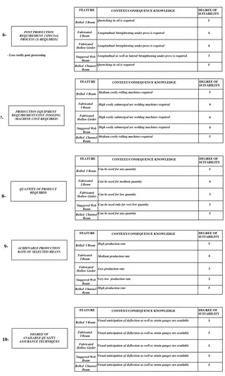
3.1.6 Post-production requirement
Post-production requirement is described as a special process that is needed after manufacturing/inscribing a solution on the component. An example of such a requirement could be retightening of a specifically designed nut in case of Hole-fastener as solution to an ‘Assembly’ function between two products during service/use. Reasoning using this type of context knowledge generates consequences about life phase systems (Maintenance/Service) and helps designer in avoiding unintended problematic/costly consequences. The consequence in this example could be the time and cost of equipment incurred in retightening of nuts. Therefore it is necessary to compare the time required and the cost of equipment that would occur during use, maintenance and service phase of a product among all the potential solutions in order to select the low cost and short lead-time solution.
3.1.7 Production equipment requirement
The knowledge related to Production Equipment Requirement comes under the category of life cycle context knowledge and deals with knowledge of Tooling/Machines required to manufacture a particular solution on a component. Timely prompting designer about the type and cost of machine/tooling that would require manufacture/realize a selected solution will help in making a cost effective decision as more costly and increased number of machines will increase the overall lead-time and product cost. An example could be the use of fine blanking dies for high surface finish in punching/blanking operation of sheet metal components instead of ordinary dies which are less costly, but requires a secondary (trimming) operation to get high surface finish of products.
3.1.8 Quantity of product required
Quantity of product/component required is an important factor in selecting a particular manufacturing solution to realize a certain function. The quantity of product directly affects the selection of production method because an expensive production method can result in high quality better selling mass manufactured product. Therefore higher equipment cost can be justified if return from the profit of mass produced components is sufficiently high. Therefore the information about quantity of product is necessary at conceptual design stage to select a suitable manufacturing solution, which can be cost effective.
3.1.9 Achievable production rate
Time required and level of difficulty to manufacture different features varies considerably. Therefore it is necessary to consider the achievable production rate of each solution using the selected production equipment before making a final decision to go ahead with the selected design solution. Higher achievable production rate will not only reduce the lead-time of the product, but also reduces the production overhead costs thus reducing the overall product cost. It is clear that the achievable production rate should be used to help evaluate design solutions, which affect the lead-time and production cost.
3.1.10Degree of available quality assurance techniques
results into low maintenance cost as well reduced time in maintenance/repair work. An example of this type of information is the availability of non-destructive testing methods such as X-Ray and ultrasound techniques to determine the strength of a metal joint during its operation/use phase.
These ten categories of context knowledge can be used for reasoning to provide decisions’ consequence awareness to the designer at the conceptual design stage. The conceptual design process is modelled as the transformation between three different information states (Welch and Dixon, 1992) which are function, behaviour and form of means/solution alternatives. This implies that conceptual design can be interpreted as function to means mapping process during which decision making takes place regarding the selection and evaluation of different design alternatives. Since a framework explaining the interactions of these three important elements (function, behaviour and form of solutions/means), therefore this research proposes a new function to means mapping model, which uses these ten categories of design context knowledge to support conceptual design decision making.
4 Function to Means Mapping Model
Conceptual design process involves deriving implementable functions by decomposing them into finer resolutions, identifying means to realise them and evaluating those means by reasoning using existing and new knowledge/information against evaluation criteria.
Observing the product from the constructional point of view (Andreasen and Hansen, 1996) gives a product break down structure (product, assembly, subassembly, component, and feature) each of which requires be designing and therefore calling as Product Design Elements (PDEs) (Borg et al., 1999). A PDE at component building level is a reusable design information unit (element) representing a potential solution means for a function requirement. Of relevance to this definition and looking from the viewpoint of component construction, a more commonly used term manufacturing feature is considered to be an information element defining a region of interest within a product.
4.1 Design context knowledge based function to PDE mapping model
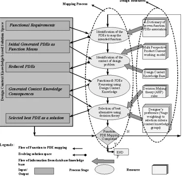
In order to support decision making at the conceptual design stage, a new generic function to PDE mapping process model is proposed here in this research (Rehman and Yan, 2003), which uses design context knowledge to support decision making as shown in Figure 1.
function to PDE mapping process. The third group (i.e. the central column of the oval shaped blocks) is called the Design Context Knowledge Based Mapping Process and describes the four stages of function to PDE mapping process, which is detailed below.
4.2 Working of the Model
The function to means mapping process takes place in four stages. At every stage during the function to means mapping process, the designer uses the inputs from the solution space and the design resources and generates new potential solution(s) thereby evolving the design solution.
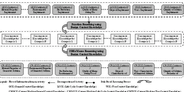
During the first stage, the designer takes the Functional Requirements and a Dictionary of Proven Function-PDEs association as inputs which result in Initial Generated PDEs as output. At the second stage, the designer takes these Initial Generated PDEs and searches for suitable models from the Multi Perspective Product Current Working Model library. This Current Working Model and the Design Context Knowledge Base are used to identify the exact context of the design problem i.e. functional requirements and solution information in different contexts. The design context knowledge base also facilitates the designer to reduce the initial set of PDEs into a reduced sub-set of PDEs, which don’t comply with the physical properties as defined in the functional requirements. During the third stage, the designer takes this reduced set of PDEs as inputs and performs function and PDEs reasoning simultaneously using the design context knowledge to generate Context Knowledge Consequences as the output of this stage as shown in Figure 2.
At the final stage of the model, the designer uses the Generated Context Knowledge Consequences, AHP rules and the Designer’s Preference as the reasoning engine and performs decision making by selecting the best solution, which not only fulfils the functional requirements, but also caters for the whole context of the design problem under consideration. This life cycle awareness is performed, by timely prompting the designer about these consequences, thereby providing proactive decision making support to the designer.
Analytic Hierarch Process is selected as the chosen decision making methods because of its following merits:
• AHP can be used for both quantitative and qualitative subjective information analysis.
• Since the desired problem of decision making in this research requires pair-wise comparison, (i.e. the chosen PDE selection problem, requires pair-wise comparison of each PDE alternative against other PDEs), the use of AHP method seems appropriate.
• This method provides comparison of different design alternatives against design criteria but also provides for comparison of different design criteria against designer’s preferences.
This whole process of function to PDE/means mapping spanning these four stages, should be iterated for all functions in a given design problem, until all functions are realized by selecting the best solutions as described above. At this stage, function to PDE mapping is completed for a design problem.
5 Case Study of Structural Component Selection
A case study of supporting conceptual design of a structural component using design context knowledge background reasoning is presented in this section. The case study is about to identify suitable PDEs/solutions to a functional requirement and then evaluate and select the best solution using context knowledge reasoning using different functionalities of the system.
Functional Requirement
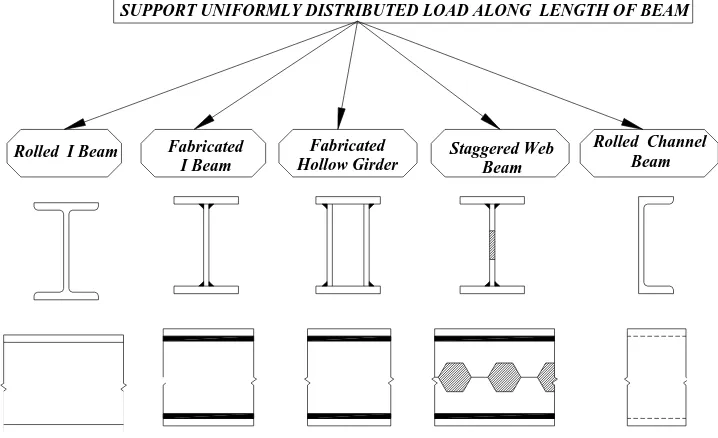
The functional requirement is to “Support Uniformly Distributed Load Along Length of Beam”.
Conceptual Solutions
Based on the functional requirements following five conceptual solutions are generated/proposed (Figure 3).
These are different types of beams and with different cross sectional shapes and manufactured through different processes. A brief description of these solutions is
• Rolled I-Beam is manufactured through rolling process and a stock/ingot of material is fed through consecutive rolling mills to achieve the required shape.
• Fabricated I-Beam is manufactured by welding two flange plates with web plate using either continuous or intermittent fillet welding.
• Fabricated Hollow Girder is manufactured by welding two flange plates with two web plates using welding.
• Staggered Web Beam is manufactured by cutting the web plate in a staggered fashion and then welding the opposite edges of web plate to increase the depth of web plate and subsequently welding it with flange plates.
• Rolled Channel Beam is manufacture through rolling process and has Channel C cross sectional shape.
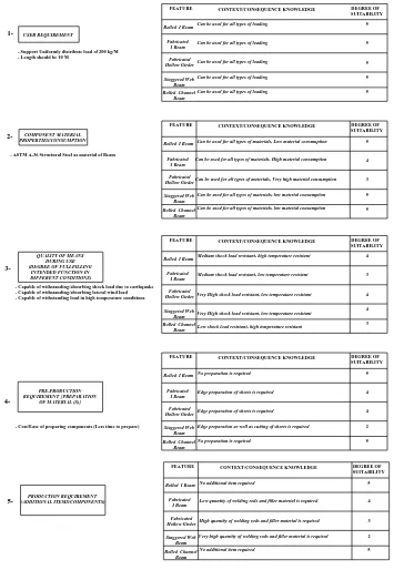
5.1 Generated Context Knowledge and Reasoning
Absolutely High=5; Very High=4; High=3; Low=2; Very Low=1; Not suitable=0.
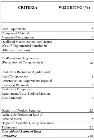
5.2 Relative Weighting and Numerical Rating
The relative weighting among ten-design knowledge criterion (preference of one criterion over other) can be done by giving percentage weighting out of 100 for each category. In this case study the relative weightings as designer’s preference is shown table 1.
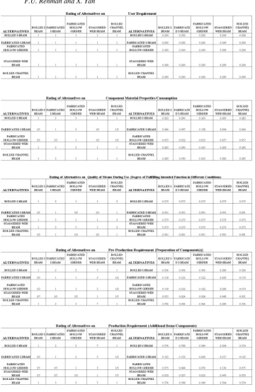
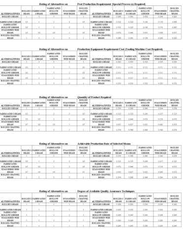
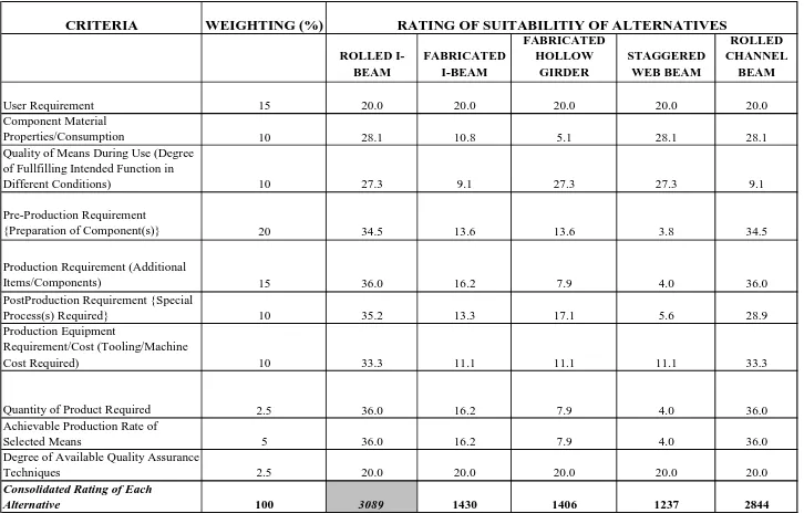
The assignment of numerical rating to each of design alternatives under each context knowledge criterion category is done by converting degree of suitability of each alternative described in previous section into weighting factor. This is done by using the comparison scales defined in decision making theory Analytic Hierarchy Process The Analytic Hierarchy Process (AHP) is a method that arranges all decisions factors in hierarchical structure, which descends from an overall goal to criteria, sub-criteria and finally to the alternatives, in successive levels. The decision maker is required to create matrices for the pair-wise comparisons for the alternatives’ performances using conversion scales against each criterion. These scales are shown in figure 5. The ratings of alternatives using these scales for each context knowledge category are shown in figures 6a and 6b.
The values in each cell of matrices are then normalized and added to determine percentage numerical rating of each alternative against a particular context knowledge criterion to determine its suitability amongst all alternatives.
5.3 Selection of best PDE/design solution
After determining relative weighting of each criteria and numerical rating of alternatives, the final task in this case study is to find the best design solution/alternative out of these five alternatives (Rolled I-Beam, Fabricated I-Beam, Fabricated Hollow Girder, Staggered Web Beam, Rolled Channel Beam,). The highest added normalized value is 3089 for Rolled I-Beam as shown in the table 2 below. Therefore Rolled I-Beam is the best solution out of all five alternatives.
The case study illustrated realisation of only one solution for a selected functional requirement. In order to realized all functional requirements all 4 stages of the model should be iterated again for each desired functional requirement, until all functions are realized by chosen/selected solutions. However the impact on the mapping of the considered function to those solutions, which have already been mapped still needs to be investigated as a future research direction of this research.
6 Conclusions
supporting in making an informed decision making. Proper formalising and structuring of design context knowledge in different categories can help a designer to use this vast amount of information and knowledge in making an effective decision making during design concept selection at conceptual design stage. By exploring the design context knowledge as shown in the presented case study, a designer can gain insights into understanding of the design problem and the solutions generated with an increasing emphasis on the product life cycle performance for a selected functional requirement. Reasoning using context knowledge can further assist individual designers to concentrate on exploring design alternatives and generate more innovative design solutions thus reducing/eliminating the chances of redesign by considering manufacturing implications and increased costs earlier at conceptual design stage due to the selection of a particular solution.
References
Andreasen, M.M. and J. Olesen (1990) ‘The Concept of Dispositions’, Journal of Engineering Design, Vol. 1, No. 1, pp. 17-36.
Andreasen, M.M. and Hansen, C.T. (1996), ‘The Structuring of Products and Product Programmes’, Proceedings of2nd WDK Workshop on Product Structuring, Delft University, The Netherlands, pp. 14-53.
Borg, C. J., and MacCallum, K.J. (1997) ‘A Life-Cycle Consequences Model Approach To The Design For Multi-X of Components’, Proceedings of the 11th International Conference on
Engineering Design (ICED97), Tampere, Finland, pp. 647-652.
Borg, C. J., Yan, X. T., Juster, N. (1999) ‘Guiding component form design using decision consequence knowledge support’, Artificial Intelligence for Engineering Design, Analysis and Manufacturing, 13, pp. 387-403.
Borg, J. C. and Yan, X.T. (1998) ‘Design Decision Consequences: Key to ‘Design For Multi-X’ Support’, Proceedings of 2nd International Symposium ‘Tools and Methods for Concurrent Engineering, Manchester, UK, pp. 169-184.
Charlton, C. and Wallace, K. (2000) ‘Reminding and context in design’, Proceedings of Artificial Intelligence in Design 2000, Massachusetts, USA, pp. 596-588.
Dorst, K. and Hendriks, D. (2001), ‘The Role of the Design Context: In Practice and in Design Methodology’, Virtual Symposium on Designing in Context, Delft University, Delft University of Technology, The Netherlands, 18-20 December 2001.
Duckworth, A.P. and Baines, R.W. (1998) ‘An Eco-Design Framework for Small and Medium Sized Manufacturing Enterprises’, Proceedings of 2nd International Symposium ‘Tools and
Methods For Concurrent Engineering’, Manchester, UK, pp. 132-141.
Duffy, A.H.B. and M.M. Andreasen (1993) ‘Design Co-ordination for Concurrent Engineering’,
Journal of Engineering Design, Vol. 4, No. 4, pp. 251-265.
Gero, J.S. (1998) ‘Conceptual designing as a sequence of situated acts’, Artificial Intelligence in Structural Engineering EdI. Smith, Springer, Berlin, pp. 165-177.
Hales, C. (1993) Managing Engineering Design. John Wiley & Sons, New York.
Hubka, V. and W.E. Eder (1988) Theory of Technical Systems: a Total Concept Theory of for Engineering Design, Springer Verlag, Berlin.
Joshi, S.P. (1991) ‘Decision making in Preliminary Engineering Design’, Artificial Intelligence in Engineering Design and Manufacture, Vol. 5, No. 1, pp. 21-30.
Kim, S., Bracewell, R.H., Wallace, K.M. (2007), ‘Improving Design Reuse Using Context’,
Proceedings of International Conference on Engineering Design, ICED07, pp. 177-178. Maffin, D. (1998) ‘Engineering Design Models: context, theory and practice’, Journal of
Mistree, F. and Smith, W. (1993) ‘A decision-based approach to concurrent design’, Concurrent
Engineering-Contemporary Issues and Modern Design Tools eds H.R. Parsaei and W.G.
Sullivan, London, Chapman & Hall, pp. 127-158.
Oxford (1998) The New Oxford Dictionary of English. Oxford University Press, UK.
Rehman F. (2006) ‘A Framework for Conceptual Design Decision Support’, PhD Thesis, CAD centre, Dept. of DMEM, University of Strathclyde, Glasgow, UK.
Rehman, F. and Yan, X.T. (2003) ‘Product design elements as means to realize functions in mechanical conceptual design’, Proceedings of 14th International Conference on Engineering Design ICED 03, Stockholm, Sweden, pp. 213.
Rehman, F. and Yan, X.T. (2004) ‘Conceptual Design Decision Making Using Design Context Knowledge’, CD-ROM Proceedings of 5th Integrated Design & Manufacture in Mechanical Engineering Conference, Bath, UK.
Rehman, F., Yan, X.T. (2007), “Supporting Early Design Decision Making Using Design Context Knowledge”, Journal of Design Research, Vol. 6, Nos. 1-2, 2007, pp. 169-189.
Roozenburg, N.F.M. and J. Eekels (1995) Product Design: Fundamentals and Methods, John Wiley & Sons: West Sussex, England.
Saaty, T.L. (1990) ‘How to Make a Decision: The Analytic Hierarchy Process’, European Journal of Operational Research, Vol. 48, pp. 9-26.
Shahare, M. Gurumoorthy, B. (2007), ‘Towards Defining Context’, Proceedings of International
Conference on Engineering Design, ICED07, pp. 175-176.
Simon, H.A. (1969) The Sciences of the Artificial. Massachusetts Institute of Technology Press, Cambridge, USA.
Starvey, C.V. (1992) Engineering Design Decisions, Edward Arnold, London.
Sudarsan, R., Fenves, S.J., Sriram, R.D., Wang, F. (2005), ‘A product information modeling framework for product lifecycle management’, Computer Aided Design, Vol. 37, pp. 1399-1411.
Welch R V and Dixon J R. (1992) Representing function, behaviour and structure during conceptual design. Proceedings of ASME Design Theory and Methodology Conference,
Scottsdale, USA, pp.11-18.
Yan, X.T., Rehman, F., Borg, J.C. (2002) ‘FORESEEing design solution consequences using design context information’ Proceedings of the Fifth IFP Workshop in Knowledge-Intensive Computer–Aided Design, Malta, pp.18-33.
Figure 3: Functional requirement and corresponding generated solutions
Rolled Channel Beam SUPPORT UNIFORMLY DISTRIBUTED LOAD ALONG LENGTH OF BEAM
Rolled I Beam Fabricated Hollow Girder Fabricated
I Beam
Can be used for all types of materials, low material consumption Can be used for all types of materials, low material consumption Can be used for all types of materials, Very high material consumption Can be used for all types of materials, High material consumption
CONTEXT/CONSEQUENCE KNOWLEDGE
Can be used for all types of materials, Low material consmuption
CONTEXT/CONSEQUENCE KNOWLEDGE
COMPONENT MATERIAL PROPERTIES/CONSUMPTION
Rolled I Beam
- ASTM A-36 Structural Steel as material of Beam
Rolled Channel Beam Fabricated Hollow Girder Staggered Web Beam Fabricated I Beam FEATURE 2-USER REQUIREMENT
- Support Uniformly distribute load of 200 kg/M - Length should be 10 M
1-Can be used for all types of loading
Can be used for all types of loading
FEATURE
Rolled Channel Beam Staggered Web
Beam
Can be used for all types of loading Can be used for all types of loading Can be used for all types of loading
Fabricated I Beam
Fabricated Hollow Girder Rolled I Beam
5 5 5 3 4 DEGREE OF SUITABILITY 5 DEGREE OF SUITABILITY 5 5 5 5
Edge preparation as well as cutting of sheets is required Low shock load resistant, high temperature resistant Very High shock load resistant, low temperature resistant Very High shock load resistant, low temperature resistant Medium shock load resistant, low temperature resistant Medium shock load resistant, high temperature resistant
CONTEXT/CONSEQUENCE KNOWLEDGE
CONTEXT/CONSEQUENCE KNOWLEDGE
Edge preparation of sheets is required Fabricated
I Beam
- Cost/Ease of preparing components (Less time to prepare)
Edge preparation of sheets is required
No preparation is required Staggered Web
Beam
Rolled Channel Beam Fabricated Hollow Girder Rolled I Beam QUALITY OF MEANS
DURING USE (DEGREE OF FULLFILLING
INTENDED FUNCTION IN DIFFERENT CONDITIONS)
- Capable of withstanding/abosrbing shock load due to earthquake - Capable of withstanding/absorbing lateral wind load - Capable of withstanding load in high temperature conditions
PRE-PRODUCTION REQUIREMENT { PREPARATION
OF MATERIAL (S)}
4-
3-Rolled Channel Beam
No preparation is required
FEATURE
Rolled I Beam Fabricated Hollow Girder Staggered Web Beam Fabricated I Beam FEATURE 4 2 5 4 4 3 DEGREE OF SUITABILITY 5 4 4 3 DEGREE OF SUITABILITY
Rolled I Beam
Staggered Web Beam
Rolled Channel Beam Fabricated Hollow Girder PRODUCTION REQUIREMENT (ADDITIONAL ITEMS/COMPONENTS) 5- Fabricated I Beam
Very high quantity of welding rods and filler material is required
No additional item required
High quantity of welding rods and filler material is required Low quantity of welding rods and filler material is required
CONTEXT/CONSEQUENCE KNOWLEDGE
No additional item required
5 2 3 4 5 FEATURE DEGREE OF
[image:17.595.114.469.144.658.2]SUITABILITY
FEATURE
Rolled I Beam
Staggered Web Beam
Rolled Channel Beam Fabricated Hollow Girder
- Less costly post processing
POST PRODUCTION REQUIREMENT { SPECIAL
PROCESS (S) REQUIRED}
6- Fabricated I Beam
Quenching in oil is required
Longitudinal as well as lateral Straightening under press is required Longitudinal Straightening under press is required Longitudinal Straightening under press is required Quenching in oil is required
5 3 4 4 5 CONTEXT/CONSEQUENCE KNOWLEDGE DEGREE OF
SUITABILITY
5
Can be used for any quantity Rolled I Beam
Staggered Web Beam
Rolled Channel Beam Fabricated Hollow Girder
Fabricated I Beam
Can be used for any quantity Can be used only for very low quantity Can be used for low quantity Can be used for medium quantity
5 2 3 4
Rolled I Beam
FEATURE
Staggered Web Beam
Rolled Channel Beam Fabricated Hollow Girder
FEATURE
QUANTITY OF PRODUCT REQUIRED PRODUCTION EQUIPMENT REQUIREMENT/COST (TOOLING
/MACHINE COST REQUIRED)
8- 7-Fabricated I Beam DEGREE OF SUITABILITY
Medium costly rolling machines required High costly submerged arc welding machines required
CONTEXT/CONSEQUENCE KNOWLEDGE
High costly submerged arc welding machines required
CONTEXT/CONSEQUENCE KNOWLEDGE
Medium costly rolling machines required
High costly submerged arc welding machines required
DEGREE OF SUITABILITY 5 4 4 4 5
Visual anticipation of deflection as well as strain gauges are available Visual anticipation of deflection as well as strain gauges are available Visual anticipation of deflection as well as strain gauges are available Visual anticipation of deflection as well as strain gauges are available
CONTEXT/CONSEQUENCE KNOWLEDGE CONTEXT/CONSEQUENCE KNOWLEDGE
Visual anticipation of deflection as well as strain gauges are available
Staggered Web Beam
Rolled Channel Beam Fabricated I Beam Fabricated Hollow Girder 10- 9-DEGREE OF AVAILABLE QUALITY ASSURANCE TECHNIQUES ACHIEVABLE PRODUCTION RATE OF SELECTED MEANS
Staggered Web Beam
High production rate
FEATURE
Rolled I Beam Rolled Channel
Beam
Very low production rate Low production rate Medium production rate High production rate
Fabricated Hollow Girder
Fabricated I Beam Rolled I Beam
[image:18.595.116.436.135.668.2]FEATURE 5 5 5 5 DEGREE OF SUITABILITY 5 5 2 3 4 5 DEGREE OF SUITABILITY
1: Both criteria of equal importance
3: Left weakly more important than top 1/3: Top weakly more important than left
5: Left moderately more important than top 1/5: Top moderately more important than left
7: Left strongly more important than top 1/7: Top strongly more important than left
9: Left absolutely more important than top 1/9: Top absolutely more important than left
Table 1: Relative weighting among 10 different design context knowledge criterion
CRITERIA
WEIGHTING (%)
User Requirement 15
Component Material
Properties/Consumption 10
Quality of Means During Use (Degree of Fullfilling Intended Function in
Different Conditions) 10
Pre-Production Requirement
{Preparation of Component(s)} 20
Production Requirement (Additional
Items/Components) 15
PostProduction Requirement {Special
Process(s) Required} 10
Production Equipment
Requirement/Cost (Tooling/Machine
Cost Required) 10
Quantity of Product Required 2.5
Achievable Production Rate of
Selected Means 5
Degree of Available Quality Assurance
Techniques 2.5
Consolidated Rating of Each
Table 2: Evaluation and selection of alternatives according to Analytic Hierarchy Process
CRITERIA WEIGHTING (%)
ROLLED I-BEAM
FABRICATED I-BEAM
FABRICATED HOLLOW
GIRDER
STAGGERED WEB BEAM
ROLLED CHANNEL
BEAM
User Requirement 15 20.0 20.0 20.0 20.0 20.0
Component Material
Properties/Consumption 10 28.1 10.8 5.1 28.1 28.1
Quality of Means During Use (Degree of Fullfilling Intended Function in
Different Conditions) 10 27.3 9.1 27.3 27.3 9.1
Pre-Production Requirement
{Preparation of Component(s)} 20 34.5 13.6 13.6 3.8 34.5
Production Requirement (Additional
Items/Components) 15 36.0 16.2 7.9 4.0 36.0
PostProduction Requirement {Special
Process(s) Required} 10 35.2 13.3 17.1 5.6 28.9
Production Equipment Requirement/Cost (Tooling/Machine
Cost Required) 10 33.3 11.1 11.1 11.1 33.3
Quantity of Product Required 2.5 36.0 16.2 7.9 4.0 36.0
Achievable Production Rate of
Selected Means 5 36.0 16.2 7.9 4.0 36.0
Degree of Available Quality Assurance
Techniques 2.5 20.0 20.0 20.0 20.0 20.0
Consolidated Rating of Each
Alternative 100 3089 1430 1406 1237 2844