For Peer Review Only
NON-INVASIVE COMPUTER-ASSISTED MEASUREMENT OF KNEE ALIGNMENT
Journal: Computer Aided Surgery
Manuscript ID: TCAS-2011-0014 Manuscript Type: Original Paper Date Submitted by the
Author: 11-Mar-2011
Complete List of Authors: Clarke, Jon; Golden Jubilee National Hospital, Orthopaedics; University of Strathclyde, Department of Bioengineering Riches, Philip; University of Strathclyde, Department of Bioengineering
Picard, Frederic; Golden Jubilee National Hospital, Orthopaedics Deakin, Angela; Golden Jubilee National Hospital, Orthopaedics Keywords: knee alignment, infrared tracking, non-invasive, computer-assisted
For Peer Review Only
Title page
NON-INVASIVE COMPUTER-ASSISTED MEASUREMENT OF KNEE
ALIGNMENT
Jon V. Clarke (MRCS)a,b, Philip E. Riches (PhD)a, Frederic Picard (MD)b, Angela H.
Deakin (PhD)a,b
a
Department of Bioengineering, University of Strathclyde, Glasgow, Scotland
b
Department of Orthopaedics, Golden Jubilee National Hospital, Clydebank, Scotland
Running title: Non-invasive measurement of knee alignment
Corresponding Author:
Mr Jon Clarke
Clinical Research Fellow
Department of Orthopaedics
Golden Jubilee National Hospital
Agamemnon Street
Clydebank
East Dunbartonshire
G81 4DY
Tel: +44 (0)141 951 5966
Fax: +44 (0)141 951 5081
Email: [email protected] 3
For Peer Review Only
Abstract
The quantification of knee alignment is a routine part of orthopaedic practice and is
important for monitoring disease progression, planning interventional strategies and
follow-up of patients. Currently available technologies such as radiographic
measurements have a number of drawbacks. The aim of this study was to validate a
potentially improved technique of measuring knee alignment under different conditions.
An image-free navigation system was adapted for non-invasive use through the
development of external infra-red tracker mountings. Stability was assessed by
comparing the variance (F Test) of repeated mechanical femoro-tibial (MFT) angle
measurements for a volunteer and a leg model. MFT angles were then measured supine,
standing and with varus-valgus stress for asymptomatic volunteers who each had two
separate registrations and repeated measurements for each condition. The mean
difference and 95% limits of agreement were used to assess intra-registration and
inter-registration repeatability. For multiple inter-registrations the range of measurements for the
external mountings was 1° larger than the rigid model with statistically similar variance
(p=0.34). Thirty volunteers were assessed (19 males, 11 females) with mean age 41 years
(20-65) and mean BMI 26 (19-34). For intra-registration repeatability, consecutive
coronal alignment readings agreed to almost ±1° with up to ±0.5° loss of repeatability for
coronal alignment measured before and after stress manoeuvres and a ±0.2° following
stance. Sagittal alignment measurements were less repeatable overall by an approximate
factor of two
Inter-registration agreement limits for coronal and sagittal supine MFT angles were ±1.6°
and ±2.3° respectively. Varus and valgus stress measurements agreed to within ±1.3° and 3
For Peer Review Only
±1.1° respectively. Agreement limits for standing MFT angles were ±2.9° (coronal) and
±5.0° (sagittal) which may have reflected a variation in stance between measurements.
The system provided repeatable, real-time measurements of coronal and sagittal knee
alignment under a number of dynamic, real-time conditions offering a potential
alternative to radiographs.
Key words: knee alignment, non-invasive, infrared tracking, computer-assisted 3
For Peer Review Only
Introduction
Knee joint alignment is an important parameter that has been extensively investigated in
the context of osteoarthritis (OA). Radiographic and magnetic resonance imaging (MRI)
studies have provided evidence that coronal malalignment is associated with an increased
incidence [1] of tibiofemoral OA and risk of progression [2-5]. The importance of
coronal alignment in reconstructive surgery of the knee has been widely accepted with
the recognition that malpositioning can lead to early prosthesis loosening [6], with
reported failure rates of 67% for varus knee prostheses versus 29% for knee prostheses in
a neutral position [7], together with increased polyethylene wear and poor overall
function [8,9]. Accurate measurement of knee alignment is therefore important for the
monitoring of patients with OA, the subsequent planning of surgical interventions and the
assessment of treatment outcomes.
The standard measurement of knee alignment often relies on clinical evaluation in
conjunction with radiographs that centre on the knee joint. However, human assessment
of angles is known to be poor [10] and the accuracy of alignment estimates under these
circumstances may be no better than the order of ±5° [11]. The use of knee radiographs
has been found to be an inaccurate measure of mechanical lower limb alignment [12] and
so its role in assessing knee alignment for planning intervention strategies and for
post-operative evaluation may be limited. Full-length hip-knee-ankle radiographs have
therefore been increasingly adopted to provide more reliable pre- and post-operative
information and are widely considered the gold standard for measuring knee alignment.
In spite of enabling measurement of the mechanical femoro-tibial (MFT) angle these 3
For Peer Review Only
radiographs are susceptible to limb positioning errors with apparent variations in
alignment produced as a result of knee flexion or rotation[13,14]. Computed tomography
(CT) imaging can overcome these positional artefacts by providing a 3D evaluation of
lower limb anatomy but is unable to provide weight-bearing information as subjects are
required to be supine. Further drawbacks of both imaging modalities include limited
availability, exposure of the pelvis to ionising radiation and the lack of more normal
physiological control data from populations not typically exposed to them such as
children and non-arthritic subjects with knee ligament injuries.
Due to the limitations of radiographs and CT scans, several alternative clinical measures
of alignment have been reported and include techniques ranging from direct visual
estimation to measurement adjuncts such as callipers, manual goniometers and
plumb-line methods [15,16]. These methods are inexpensive, avoid radiation exposure and are
relatively quick to perform with instant measurement results. However the reported errors
are potentially too large for use in planning and follow-up of surgical interventions such
as replacement arthroplasty and corrective osteotomy where higher levels of accuracy are
often required[16].
Out with the clinic situation a number of new technologies using infrared tracking have
been introduced intra-operatively to provide surgeons with quantitative measurement
tools that permit real time assessment of lower limb kinematics [17-19]. These systems
have high levels of precision and can achieve angular and tibiofemoral gap measurements
of within 1° or 1mm respectively [20,21]. At present these quantitative measurement
For Peer Review Only
techniques have restricted scope due to their reliance on the rigid bony fixation of
trackers. Adapting this technology for non-invasive patient assessment is challenging due
to the soft tissue artefacts associated with the external mounting of trackers. Previous
investigations to quantify the relative movement of external marker sets relative to
underlying bones have reported large potential errors and questioned the value of these
methods for accurate kinematic analysis[22,23]. However these functional methods of
determining rotational joint centres and resultant mechanical lower limb alignment are
often in the context of gait analysis or involve active joint movement with contraction of
the underlying muscles. A more recent study sought to minimise [24] these potential
artefacts by measuring static standing lower limb alignment with position capture and
skin markers along with external anatomical landmarks. The reliance on anthropometric
measurements to predict joint centre location may have accounted for only a moderate
correlation with corresponding long-leg radiographs in an experimental set-up not readily
adaptable to an out-patient clinic.
Given the subjective nature of clinical examination and the limitations of different
measurement techniques reported to date, there is potential to improve current methods of
assessing knee joint alignment. This paper reports the validation of a non-invasive system
for measuring lower limb alignment based on a commercially available infrared tracking
technology with kinematic registration. Our hypothesis was that repeatable, real-time
measurements of mechanical knee alignment under a number of conditions could be
obtained in a clinic situation. 3
For Peer Review Only
Materials and Methods
Infra-red tracking system
An image-free navigation system (Orthopilot®, BBraun Aesculap, Tuttlingen, Germany),
that consisted of an optical localiser, active infrared (IR) trackers, apre-calibrated probe
to digitise anatomical landmarks and a foot pedal that enabled ‘hands-free’ data recording
was chosen due to its current clinical use. High tibial osteotomy (HTO) software
(Orthopilot® HTO version 1.5, BBraun Aesculap, Tuttlingen, Germany) was used for the
kinematic determination of hip, knee and ankle centres and resultant generation of
coronal and sagittal MFT angles. Coronal alignment was defined with varus negative and
valgus positive, whilst sagittal alignment was defined with hyperextension negative and
flexion positive.
Rigid tracker mounting model
A metal lower limb model was designed and manufactured to provide optimum
conditions for measuring knee alignment. This consisted of metal rods representing a
femur, tibia and a foot with rigidly attached tracker mounts and mechanical hip, knee and
ankle joints with the required range of movement for registration of their rotational
centres (Figure 1).
Non-invasive tracker mounting
Tracker mountings for the thigh, calf and mid-foot regions were developed using metal
base plates and broad straps made from standard strength elastic webbing (542, E&E 3
For Peer Review Only
Accessories, UK). A variety of lengths were made with a sequence of eyelets at either
end to connect to the base plate and enable further adjustment of strap size (Figure 2).
Tracker stability testing
In order to quantify the soft tissue artefacts of the non-invasive mountings, the
repeatability of the measurement of coronal knee alignment for both the leg model and
for the right lower limb of a slim, female volunteer was determined. The volunteer was
asked to relax whilst lying supine on an examination couch to ensure that all movements
were passive. The registration process followed that which would be employed
intra-operatively in the normal use of the software. It began with the identification of the
kinematic centre of the hip joint which required a slow, controlled circumduction of the
thigh. The manoeuvre was performed in this manner to avoid moving the pelvis and
subsequently altering the location of the rotational centre of the femoral head. If there
was excessive movement of the pelvis or the trackers, then this could have resulted in a
wider, “non-spherical” spread of acquired hip joint centre (HJC) points that was out with
the required precision of the system [25]. This would result in rejection of the HJC
acquisition and the instruction to repeat the circumduction manoeuvre until the spread of
measured points was within the required threshold. The kinematic ankle centre was
determined next by attaching a tracker to the dorsum of the foot and then dorsi-flexing
and plantar-flexing the ankle. The rotational centre of the knee joint was then acquired by
flexing and extending the knee between 0 and 90° as well as rotating the tibia on the
femur at 90° of flexion. Following a single registration the trackers were left in position
and 20 consecutive MFT angle recordings were made with the rigid leg model stationary 3
For Peer Review Only
and with the volunteer instructed to remain as still as possible. The full registration
process was then repeated a further 20 times on 13 different days to quantify additional
soft tissue artefacts associated with removal and re-attachment of the trackers. Statistical
analysis was performed using SPSS version 17 (SPSS Inc, Chicago, IL, USA) and F tests
used for comparison of the variances of the repeated data sets
Repeatability testing
All experimental procedures were approved by the University Ethics Committee and,
after giving informed consent, 30 volunteers were recruited (19 males and 11 females)
with a mean age of 41 years (range 20-65) and a mean body mass index (BMI) of 26
(range 19-34). Participants confirmed no acute knee symptoms and no history of joint
replacement. Basic demographic data were recorded prior to assessment of the right
lower limb. Two kinematic registration processes were performed using the appropriate
passive clinical manoeuvres described above. After each registration, the immediate
coronal and sagittal alignments in full extension were recorded with the lower limb
supported at the heel and the subject told to relax. Following this, coronal and sagittal
alignment was measured with subjects asked to assume their normal bipedal stance.
Returning the participant to the supine position, the coronal and sagittal alignment
measurements were then performed twice and subsequent to this five manual stresses
were applied to the knee joint by a single clinician to determine varus and valgus angular
displacements. During these stress manaouevres, the knee was held between 0° and 5° of
flexion as indicated by the on-screen measurement of sagittal MFT angle. If the knee
coud not extend to 0° then the stress measurments were performed within a 5° window of 3
For Peer Review Only
flexion from the maximum extension angle. Following this, the coronal and sagittal
alignment measurements were finally repeated twice again. Thus five coronal and sagittal
MFT angles were determined, before and after standing and before and twice after five
bouts of varus-valgus stressing. The clinician was blinded to all the recorded alignment
measurements except for the initial supine coronal MFT angle following registration.
Occasionally, this measurement after the second registration did not agree to within 2° of
the first registration and if this occurred, the registration process was repeated. The limit
of 2° was based on the acceptance of small anticipated loss of accuracy due to soft tissue
artefacts in comparison to the reported 1° accuracy for invasive use [21].
The mean difference and Bland-Altman 95% limits of agreement [26] of supine coronal
MFT angles taken consecutively, and before and after standing and collateral stress
within each trial were measured. This was used as an indirect measure of any
intra-registration tracker movement that may have occurred during manipulation of the lower
limb or from the subject actively moving between supine and standing positions. The
mean difference and 95% agreement limits were also used to assess inter-registration
agreement of MFT angles measured supine, standing and following applied collateral
stress. Bland-Altman plotswere generated for the inter-registration comparative data sets.
When more than one measurement of a variable was taken within a trial the median value
was used. 3
For Peer Review Only
Results
Tracker Stability
Comparison of the rigid and non-invasive mounts is shown in Table 1. Consecutive
readings of coronal alignment following a single registration demonstrated standard
deviations of 0.07° and 0.13° for the rigid leg model and volunteer respectively and the
variances were found to be statistically different (p < 0.01). For multiple registrations on
different days the overall range was 1° larger for the non-invasive volunteer mounting but
the SD was still less than 1° for both tracker mounting methods with no statistically
significant difference in the variance of the groups.
Repeatability
The overall cohort had a mean supine coronal MFT angle of 0.1 ± 2.5° and corresponding
sagittal MFT angle of -1.7 ± 3.3° (mean ± SD).The intra-registration agreement of MFT
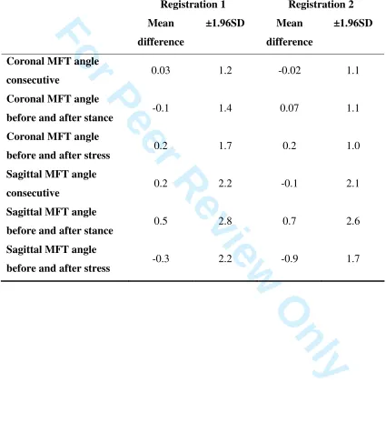
angle measurements is shown for each of the two sets of registrations in Table 2. Repeat
coronal alignment readings with the volunteer lower limbs stationary agreed to almost
±1° for both the first and second registrations. For the first registration there was an
approximate ±0.5° loss of repeatability for coronal alignment measured before and after
collateral stress manoeuvres and a less significant loss of ±0.2° following stance trials.
These small losses in coronal MFT angle repeatability were not seen for the second
registration with a consistent agreement of approximately ±1°. Sagittal alignment
measurements were less repeatable overall by an approximate factor of two and were
generally no more precise for consecutive stationary readings. 3
For Peer Review Only
The agreement between the two registrations (Table 3) indicated a repeatability of
approximately ±1° for all the supine coronal alignment measurements including change
with applied stress. On three occasions, a third registration process was required to obtain
two registrations with a difference in supine coronal MFT angle of 2° or less.
Standing alignment measurements showed less agreement for both coronal (±3°) and
sagittal (±5°) MFT angles. These results are illustrated in Bland-Altman plots (figures
3a-f). 3
For Peer Review Only
Discussion
The quantification of knee alignment is a routine part of orthopaedic practice and is
important for the monitoring of disease progression, the planning of interventional
procedures and the follow up of patients. Currently available technologies and
measurement techniques have a number of drawbacks including inaccuracy, limb
positioning artefacts and radiation exposure. This study developed a system that has
addressed some of these issues.
The stability of the IR tracker mountings permitted non-invasive kinematic measurement
of knee alignment. For a single volunteer, the non-invasive attachments compared well
with the rigid mountings of the leg model. The variance of volunteer measurements for
repeated consecutive MFT angles on one registration was statistically greater than that of
the rigidly fixed mounting but this difference is of doubtful clinical significance given
that both set-ups were well within a precision of 1°. For repeated registrations, the SD of
the non-invasive mounting was a third higher than the leg model and the actual range was
1° larger with no statistical difference between the two. This result was perhaps
surprising given that the leg model had a rigid hinge for a knee joint with no collateral
movement and therefore a more consistent MFT angle. The only minor source of
variation between trials on different days was the coupling mechanism between the
trackers and fixation screws. In comparison, the volunteer straps would not have been
identically applied in terms of both position and tightness. Furthermore, the small amount
of natural collateral laxity of the volunteer knee could potentially have resulted in real
differences in alignment on different days. 3
For Peer Review Only
Further evaluation of the non-invasive tracker mountings was provided by the assessment
of multiple volunteers. Following registration the lower limb coronal and sagittal MFT
angles could be repeatedly measured in real-time permitting an intra-registration
assessment of tracker stability following stance and varus-valgus stress. These limb
movements could have potentially modified tracker position but qualitatively they
appeared stable throughout and remained in position for the duration of the measurements
with no complaints of discomfort. This observation of stability was reflected in the results
for consecutive coronal MFT angle measurements in comparison to those taken before
and after stance and collateral stress of the knee. All repeatability was within levels of
clinical relevance. For sagittal alignment the measurements were less repeatable overall
within both sets of registrations with the poorest agreement of up to almost ±3° seen
before and after stance. However this may reflect a true difference in sagittal MFT angles
rather than a change in tracker position. Some volunteers were noted to have poor
relaxation which often improved throughout the course of the assessment with less
resistance to full extension from the hamstring muscles. This resulted in a tendency for
knees to become more extended towards the end of the trials which could potentially
explain the greater variation in sagittal measurements in comparison to coronal MFT
angles which were less likely to be affected by muscle tone.
The limits of agreement between the two sets of registrations were approximately ±1° for
all supine alignments including change with applied stress. For the initial supine coronal
alignment measurements only three gave inconsistent results that required repetition. All 3
For Peer Review Only
repetitions were acceptable. Therefore although the registration process was open to error
it was an infrequent occurrence and a simple repeat protocol enabled it to be identified
every time. The potential variation in applied manual load to the knee did not result in a
loss of repeatability that would perhaps have been anticipated. This may be explained by
the consistency of the clinician performing the collateral stress manoeuvres[27] which
may have shown greater inter-observer variation if different examiners were assessed.
Standing alignment measurements showed less agreement for both coronal (±3°) and
sagittal (±5°) MFT angles. This may represent a true difference in alignment as a result of
stance variation between trials as volunteers were only instructed to stand on both legs as
normal rather than to assume a position of maximum extension with their knees “locked”
straight. Therefore the variation in standing knee extension angle could be due to this
lack of control of limb position. In comparison the supine measurements were performed
in a more reproducible manner by supporting the lower limb under the heel and this was
reflected in the narrower agreement limits illustrated with Bland-Altman plots. The ±5°
scale of the vertical axis (except for standing sagittal measurements) was chosen to
reflect typical repeatability of other methods of assessing both sagittal[10] and coronal
[24] knee alignment including human variations of joint angle estimation[11]. However
it should be noted that considerably greater intra-observer estimates of knee flexion and
extension angles have been reported with critical differences between measurements of
7.1° to 21.4°[28].
The use of externally mounted markers and a motion capture system was not an entirely
novel approach to measuring lower limb alignment. Mündermann et al. [24] used
For Peer Review Only
reflective marker sets and four high-speed cameras to measure static mechanical lower
limb alignment but reported only a moderate correlation (R2=0.544) with the
corresponding long-leg radiographs and a discrepancy of more than 5.3° for 10% of
cases. However, the hip, knee and ankle joint centres were determined from
anthropometric measurements which are widely accepted as being inaccurate, particularly
for the hip joint [29-32]. The experimental set up in terms of anatomical landmark
identification, marker placement, multiple camera positioning and data capture analysis
also presented several limitations as a clinically adaptable measurement tool. In contrast,
the system developed in this study consisted of a single portable camera unit with
corresponding IR trackers that should be secure and visible but without the requirement
of specific anatomical placement. The kinematic registration process was approximately
five minutes with on-screen guidance for performing simple joint movements to
determine their rotational centres. The subsequent MFT angle was generated from
kinematic data alone without the potential associated errors of anatomical landmark
registration[33]. Hip joint centre location errors were minimised by a software algorithm
that rejected the points in space acquired during thigh circumduction if their spread was
too large or the distribution was non-spherical [25]. The passive movements for
kinematic registration were therefore required to be slow and controlled, which contrasts
to other studies of functional joint centre determination using active movements or gait
[22,23].
The immediate generation of real-time on-screen coronal and sagittal MFT angles
presented a number of potential advantages over other measurement systems. Firstly it 3
For Peer Review Only
enabled dynamic measurements of alignment to be made following applied stress or
weight bearing with immediate visualisation of angular displacement. The ability to
measure the resultant change in coronal MFT angle from a supine resting position when a
collateral stress is applied has a potential clinical application for improving the
measurement of relative varus and valgus knee laxity. Current methods are either
subjective [34] or rely on adjuncts such as X-ray measurements of tibiofemoral gap
opening [35] which are prone to potential radiographic errors associated with limb
positioning [13,14]. For weight-bearing conditions the measurements did not require
strict rotational control of the lower limb and the coronal MFT angle was recorded with
the associated knee flexion angle. This IR system could therefore potentially offer a
viable alternative to long-leg radiographs whilst also overcoming some of the previously
discussed limitations.
This validation study also has its limitations. The measurements were made by a single
clinician involved in the development of the system without an assessment of
inter-observer variation. The true volunteer knee alignments were unknown and so validation
of the measurement tool was based on repeatability rather than comparison to a
measurement standard. However, the IR measurement system is validated for use with
rigid tracker attachments. It could therefore be inferred that repeatable measurements are
also accurate, as for measurements to be repeatable, soft tissue artefacts must be minimal.
In addition, it could be argued that the acknowledged long-leg radiographic gold standard
has more potential variation [14] than the IR system and that disagreement between
measurements may not reflect true inaccuracies[36]. Although there were several obese
For Peer Review Only
subjects, there were none who were morbidly obese and no subject reported discomfort
when performing the necessary kinematic manoeuvres. The registration process may be
less reliable in a typically more obese osteoarthritic population[37,38] with potential pain
on joint movement.
In summary, a non-invasive tool for measuring coronal and sagittal knee alignment under
a number of dynamic, real-time conditions was developed and validated. The portability
of the system offers potential as an out-patient assessment tool and provides an
alternative to long-leg radiographs without exposure to radiation. The measurement of
supine, standing and stress alignment on both asymptomatic and osteoarthritic subjects
may help to further our understanding of the complex kinematics of the knee. 3
For Peer Review Only
Declaration of interest statement
One of the authors (FP) has patents/licensing agreements with BBraun Aesculap. JVC,
PER and AHD certifies that he or she has no commercial associations (e.g. consultancies,
stock ownership, equity interest, patent/licensing arrangements, etc.) that might pose a
conflict of interest in connection with the submitted article. Our department has received
research funding from BBraun Aesculap. 3
For Peer Review Only
References
1. Sharma L, Song J, Dunlop D, Felson D, Lewis CE, Segal N, Torner J, Cooke TDV,
Hietpas J, Lynch J, Nevitt M. Varus and valgus alignment and incident and progressive
knee osteoarthritis. Ann Rheum Dis doi:10.1136/ard.2010.129742
2. Sharma L, Song J, Felson DT, Cahue S, Shamiyeh E, Dunlop DD. The role of knee
alignment in disease progression and functional decline in knee osteoarthritis. JAMA
2001;286:188-195.
3. Cerejo R, Dunlop DD, Cahue S, Channin D, Song J, Sharma L. The influence of
alignment on risk of knee osteoarthritis progression according to baseline stage of
disease. Arthritis Rheum 2002;46(10):2632-2636.
4. Cicuttini F, Wluka A, Hankin J, Wang Y. Longitudinal study of the relationship
between knee angle and tibiofemoral cartilage volume in subjects with knee
osteoarthritis. Rheumatology 2004;43:321-324.
5. Tanamas S, Hanna FS, Cicuttini FM, Wluka AE, Berry P, Urquhart DM. Does knee
malalignment increase the risk of development and progression of knee osteoarthritis? A
systematic review. Arthritis Rheum 2009;61(4):459-467.
6. Garg A, Walker PS. Prediction of total knee motion using a three-dimensional
computer-graphics model. J Biomech 1990;23:45-48.
7. Bargren JH, Blaha JD, Freeman MAR. Alignment in total knee arthroplasty: correlated
biomechanical and clinical investigations. Clin Orthop Relat Res 1983;173:178-183.
8. Oswald MH, Jakob RP, Schneider E, Hoogewoud HM. Radiological analysis of
normal axial alignment of femur and tibia in view of total knee arthroplasty. J
Arthroplasty 1993;8:419-426. 3
For Peer Review Only
9. Wasielewski RC, Galante JO, Leighty R, Natarajan RN, Rosenberg AG. Wear patterns
on retrieved polyethylene tibial inserts and their relationship to technical considerations
during total knee arthroplasty. Clin Orthop 1994;299:31-43.
10. Edwards JZ, Greene KA, Davis RS, Kovacik MW, Noe DA, Askew MJ. Measuring
flexion in knee arthroplasty patients. J Arthroplasty 2004;19(3):369-372.
11. Markolf KL, Mensch JS, Amstutz HC. Stiffness and laxity of the knee– the
contributions of the supporting structures. J Bone Joint Surg [Am] 1976;58-A:583-594.
12. van Raaija TM, Brouwerc RW, Reijmana M, Bierma-Zeinstrab SMA, Verhaara JAN.
Conventional knee films hamper accurate knee alignment determination in patients with
varus osteoarthritis of the knee. The Knee 2009;16(2):109-111.
13. Krackow KA, Pepe CL, Galloway EJA. A mathematical analysis of the effect of
flexion and rotation on apparent varus/valgus alignment at the knee. Orthopaedics
1990;13(8):861-868.
14. Siu D, Cooke TD, Broekhoven LD, Lam M, Fisher B, Saunders G et al. A
standardised technique for lower limb radiography. Practice, applications, and error
analysis. Invest Radiol 1991;26(1):71-77.
15. Kraus VB, Vail TP, Worrell T, McDaniel G. A comparative assessment of alignment
angle of the knee by radiographic and physical examination methods. Arthritis Rheum
2005;52(6):1730-1735.
16. Hinman RS, May RL, Crossley KM. Is there an alternative to the full-leg radiograph
for determining knee joint alignment in osteoarthritis? Arthritis Care Res
2006;55(2):306-313. 3
For Peer Review Only
17. Stulberg DS, Loan P, Sarin V. Computer-assisted navigation in total knee
replacement: results of an initial experience in thirty-five patients. J Bone Joint Surg
[Am] 2002;84-A;90-98.
18. Bathis H, Perlick L, Tingart M, Luring C, Zurakowski D, Grifka J. Alignment in total
knee arthroplasty: comparison of computer-assisted surgery with the conventional
technique. J Bone Joint Surg [Br] 2004;86-B:682-687.
19. Chauhan SK, Scott RG, Breidahl W, Beaver RJ. Computer-assisted knee arthroplasty
versus a conventional jig-based technique: a randomized, prospective trial. J Bone Joint
Surg [Br] 2004;86-B:372-377.
20. Stockl B, Nogler M, Rosiek R, Fischer M, Krismer M, Kessler O. Navigation
improves accuracy of rotational alignment in total knee arthroplasty. Clin Orthop Relat
Res 2004;426:180-186.
21. Haaker RG, Stockheim M, Kamp M, Proff G, Breitenfelder J, Ottersbach A.
Computer-assisted navigation increases precision of component placement in total knee
arthroplasty. Clin Orthop Relat Res 2005;433:152–159.
22. Stagni R, Fantozzi S, Cappello A, Leardini A. Quantification of soft tissue artefact in
motion analysis by combining 3D fluoroscopy and stereophotogrammetry: a study on two
subjects. Clin Biomech 2005;20:320-329.
23. Sangeux M, Marin F, Charleux F, Dürselen L, Ho Ba Tho MC. Quantification of the
3D relative movement of external marker sets vs. bones based on magnetic resonance
imaging. Clin Biomech 2006;21:984-991.
24. Mündermann A, Dyrby CO, Andriacchi TP. A comparison of measuring mechanical
axis alignment using three-dimensional position capture with skin markers and 3
For Peer Review Only
radiographic measurements in patients with bilateral medial compartment knee
osteoarthritis. The Knee 2008;15:480-485.
25. Picard F, Gregori A, Leitner F. Computer assisted total knee arthroplasty: validation
of the image free concept. Berlin, Germany: Pro Business, 2007:182-301.
26. Bland JM, Altman DG. Statistical methods for assessing agreement between two
methods of clinical measurement. Lancet 1986;1:307-310.
27. Clarke JV, Deakin AH, Nicol AC, Picard F. Varus and valgus stress of the knee joint:
does a reliable end-point exist? IMechE event proceedings, Knee arthroplasty: From early
intervention to revision 2009:65-69.
28. Cushnaghan J, Cooper C, Dieppe P, Kirwan J, McAlindon T, McCrae F. Clinical
assessment of osteoarthritis of the knee. Ann Rheum Dis 1990;49:768-770.
29. Bell AL, Pedersen DR, Brand RA. A comparison of the accuracy of several hip centre
location prediction methods. J Biomech 1990;23(6):617-621.
30. McGibbon CA, Riley PO, Krebs DE. Comparison of hip centre estimation using
in-vivo and ex-in-vivo measurements from the same subject. Clin Biomech
1997;12(7/8):491-495.
31. Leardini A, Cappozzo A, Catani F, Toksvig-Larsen S, Petitto A, Sforza V et al.
Validation of a functional method for the estimation of hip joint centre location. J
Biomech 1999;32:99-103.
32. Hicks JL, Richards JG. Clinical applicability of using spherical fitting to find hip joint
centres. Gait & Posture 2005;22:138-145.
33. Robinson M, Eckhoff DG, Reinig KD, Bagur MM, Bach JM. Variability of landmark
identification in total knee arthroplasty. Clin Orthop Relat Res 2006;442:57-62. 3
For Peer Review Only
34. Krackow KA. Varus deformity. The technique of total knee arthroplasty. St Louis,
CV Mosby Co, 1990:317-340.
35. LaPrade RF, Heikes C, Bakker AJ, Jakobsen RB. The Reproducibility and
Repeatability of Varus Stress Radiographs in the Assessment of Isolated Fibular
Collateral Ligament and Grade-III Posterolateral Knee Injuries. An in Vitro
Biomechanical Study. J Bone Joint Surg [Am] 2008;90:2069-2076.
36. Yaffe MA, Koo SS, Stulberg SD. Radiographic and navigation measurements of
TKA limb alignment do not correlate. Clin Orthop Rel Res 2008;466(11):2736-2744.
37. Amin AK, Patton JT, Cook RE, Brenkel IJ. Does obesity influence the clinical
outcome at five years following total knee replacement for osteoarthritis? J Bone Joint
Surg [Br] 2006;88-B(3):335-340.
38. Dowsey MM, Liew D, Stoney JD, Choong PF. The impact of pre-operative obesity
on weight change and outcome in total knee replacement – a prospective study of 529
consecutive patients. J Bone Joint Surg [Br] 2010;92-B(4):513-520. 3
For Peer Review Only
Table 1 The mean and standard deviation (SD) of each set of tests was used to compare
the difference in repeatability of the rigid model and the non-invasive tracker mounting
(measurements in degrees)
Single registration Multiple registrations
Leg Model:
Rigid
mounting
Volunteer:
Non-invasive
mounting
Leg Model:
Rigid mounting
Volunteer:
Non-invasive
mounting
n 20 20 20 20
Mean (SD) 2.1 (0.07) 1.4 (0.13) 1.6 (0.5) 1.5 (0.7)
range 2.0 – 2.3 1.1 – 1.6 0.9 – 2.8 0.3 – 2.5
F Test p = 0.008 p =0.34
For Peer Review Only
Table 2 Mean difference and 95% limits of agreement of repeat supine alignment
measurements in extension with leg stationary and before and after both standing and
collateral stress manoeuvres (measurements in degrees)
Registration 1 Registration 2
Mean
difference
±1.96SD Mean
difference
±1.96SD
Coronal MFT angle
consecutive 0.03 1.2 -0.02 1.1
Coronal MFT angle
before and after stance -0.1 1.4 0.07 1.1
Coronal MFT angle
before and after stress 0.2 1.7 0.2 1.0
Sagittal MFT angle
consecutive 0.2 2.2 -0.1 2.1
Sagittal MFT angle
before and after stance 0.5 2.8 0.7 2.6
Sagittal MFT angle
before and after stress -0.3 2.2 -0.9 1.7
[image:27.612.83.508.171.636.2]For Peer Review Only
Table Error! No text of specified style in document. Inter-registration agreement of
supine and standing coronal and sagittal MFT angles, and relative change following
varus-valgus stress (measurements in degrees)
MFT angle Mean difference ±1.96SD
Supine coronal -0.2 0.8
Supine sagittal 0.2 1.2
Change with varus stress -0.3 1.3
Change with valgus stress -0.2 1.1
Standing coronal 0.2 2.9
Standing sagittal 0.1 5.0
[image:28.612.82.524.169.723.2]For Peer Review Only
Figure legends
Figure 1: Leg model with rigid tracker mountings
Figure 2: External tracker mountings with adjustable straps
Figures 3a-f: Bland-Altman plots showing the mean difference (solid black line) and
95% limits of agreement (dotted grey lines) of MFT angular measurements for two trials
a) supine coronal, b) supine sagittal, c) with varus stress, d) with valgus stress, e)
standing coronal, f) standing sagittal 3
For Peer Review Only
Leg model with rigid tracker mountings 160x107mm (150 x 150 DPI) 3
For Peer Review Only
External tracker mountings with adjustable straps 100x66mm (150 x 150 DPI)
For Peer Review Only
-5 -4 -3 -2 -1 0 1 2 3 4 5-6 -5 -4 -3 -2 -1 0 1 2 3 4 5 6
D if fe re n ce b et w ee n s u p in e co ro n a l M F T a n g le s (º )
Average of supine coronal MFT angles (º)
Inter-registration limits of agreement
-5 -4 -3 -2 -1 0 1 2 3 4 5
-9 -8 -7 -6 -5 -4 -3 -2 -1 0 1 2 3 4 5 6 7 8 9
D if fe re n ce b et w ee n s u p in e sa g it ta l M F T a n g le s (º )
Average of supine sagittal MFT angles (º)
Inter-registration limits of agreement
-5 -4 -3 -2 -1 0 1 2 3 4 5
-6 -5 -4 -3 -2 -1 0
D if fe re n ce b et w ee n v a ru s st re ss d is p la ce m en t a n g le s (º )
Average of varus stress displacement angles (º)
Inter-registration limits of agreement
For Peer Review Only
-5 -4 -3 -2 -1 0 1 2 3 4 50 1 2 3 4 5 6 7
D if fe re n ce b et w ee n v a lg u s st re ss d is p la ce m en t a n g le s (º )
Average of valgus stress displacement angles (º)
Inter-registration limits of agreement
-5 -4 -3 -2 -1 0 1 2 3 4 5
-9 -8 -7 -6 -5 -4 -3 -2 -1 0 1 2 3 4 5 6
D if fe re n ce b et w ee n s ta n d in g c o ro n a l M F T a n g le s (º )
Average of standing coronal MFT angles (º)
Inter-registration limits of agreement
-7 -6 -5 -4 -3 -2 -1 0 1 2 3 4 5 6 7
-16-15-14-13-12-11 -10 -9 -8 -7 -6 -5 -4 -3 -2 -1 0 1 2 3 4 5 6 7 8 9 10
D if fe re n ce b et w ee n s ta n d in g s a g it ta l M F T a n g le s (º )
Average of standing sagittal MFT angles (º)
Inter-registration limits of agreement