City, University of London Institutional Repository
Citation
:
Egyed, A., Medvidovic, N. and Gacek, C. (2000). Component-based perspective
on software mismatch detection and resolution. IEE Proceedings: Software, 147(6), pp.
225-236. doi: 10.1049/ip-sen:20000915
This is the unspecified version of the paper.
This version of the publication may differ from the final published
version.
Permanent repository link: http://openaccess.city.ac.uk/252/
Link to published version
:
http://dx.doi.org/10.1049/ip-sen:20000915
Copyright and reuse:
City Research Online aims to make research
outputs of City, University of London available to a wider audience.
Copyright and Moral Rights remain with the author(s) and/or copyright
holders. URLs from City Research Online may be freely distributed and
linked to.
City Research Online: http://openaccess.city.ac.uk/ [email protected]
A Component-Based Perspective on
Software Mismatch Detection and Resolution
Alexander Egyed
Computer Science Department
University of Southern California
Los Angeles, CA 90089-0781, USA
Nenad Medvidovic
Computer Science Department
University of Southern California
Los Angeles, CA 90089-0781, USA
Cristina Gacek
Fraunhofer IESE
Sauerwiesen 6
67661 Kaiserslautern, Germany
ABSTRACT
Existing approaches to modeling software systems all too often neglect the issue of component mismatch
identification and resolution. The traditional view of software development over-emphasizes synthesis at the expense of
analysis - the latter frequently being seen as a problem one only needs to deal with during the integration stage towards
the end of a development project. This paper discusses three software modeling and analysis techniques, all tool
supported, and emphasizes the vital role analysis can play in identifying and resolving risks early on. This work also
combines model based development with component based development (e.g., COTS and legacy systems) and shows
how their mismatch detection capabilities complement each other in providing a more comprehensive coverage of
development risks.
KEYWORDS
Component-based Architectures, Component Integration, Rapid Component Compatibility Validation, Tools,
Process support for Component-Based Modeling.
1 INTRODUCTION
Nowadays, in order to be competitive, a developer’s usage of Commercial-off-the-Shelf (COTS) packages has
become standard, at times being an explicit requirement from the customer. The idea of simply plugging together various
COTS packages and/or other existing/in-house developed parts (as described in the mega-programming principles [1]) is
Likewise, the development of architectural and design modeling languages (e.g., Unified Modeling Language [3]) has
proceeded with little emphasis towards new challenges imposed by component-based development.
This work introduces a three-tiered development methodology that combines independently created
component-based and model-component-based development approaches [4]. Our combined approaches complement one another in their ability
to detect a larger (more comprehensive) number of mismatches that may happen between various component choices.
Our combined approaches also complement one another in the speed which they provide mismatch feedback. More
comprehensive mismatch analysis has the benefit of an increased likelihood that incompatibilities between components
are identified before the actual software system is built, potentially preventing great loss of cost and effort. Rapid
mismatch detection has the additional benefit of a fast exclusion of non-viable component configurations (architectures)
for a desired system, again reducing cost and effort required in analyzing a potentially large set of components.
Our approach performs (1) a high-level component analysis followed by (2) a more comprehensive
component-enabled architectural analysis, excluding unfeasible architectural options along the way. Both analysis approaches detect
mismatches and thus help human decision makers in eliminating unfeasible architectural options. Our analysis
approaches act as filters where unfeasible options are removed before the next analysis step. The first filter is fast and
can provide feedback within hours, but is not very comprehensive. The second filter is more comprehensive and thus
slower, but more reliable. In order to ensure continuity between them we also created a synthesis technique to share
modeling information between them (e.g., use of analysis results of the first filter as an input to the second filter).
The fact that our analysis filters trade off precision with speed has another beneficial side effect. During software
development we are (at times) confronted with both the lack of information and its abundance. Whenever we deal with
new issues, variables, changes, and so on (e.g., new requirements) we usually lack information and our ability to analyze
its impact seems limited. Conversely, once some aspect has been investigated, we are often confronted with a plethora of
information spread across multiple models (e.g. documents, design models, implementation). Our dual filtering process
can handle both situations. We find the first filter being most effective early on in the software life cycle – as early as
requirements negotiation – where choices of components, their features, and configurations are still very vague. Our
second filter requires more detailed information that becomes available later on. Architectural analysis techniques [5]
used in our second filter frequently also support refinement, making it possible to use the second filter recursively for
The third tier of our development approach is a synthesis technique supporting the consistent refinement of viable
architectural options (determined via the first two steps) into end-user-applications. After all, regardless how pretty an
architectural model looks and how effective it is in addressing stakeholder requirements, it adds little value to the final
product unless the information specified through it can somehow be transitioned into the final product. Consistent
refinement is thus necessary to ensure that architectural options, which passed our analysis filters, are subsequently
implemented correctly.
The contributions of this paper are an incremental, rapid, and comprehensive approach to component-based
software modeling with a strong emphasis on component mismatch detection and consistent refinement. In following,
this paper will introduce and discuss our three-tier development approach. To complement the discussion, a non-trivial
example is used to illustrate our approach. The three sections discussing the individual pieces of our approach are
structured by giving an initial high level and generic overview, followed by a demonstration in context of the example,
and concluded with a follow-up discussion on how other scenarios may require a different treatment than the one given
in the example. Due to the limited space, references are provided whenever the details cannot be discussed in this paper.
2 APPROACH
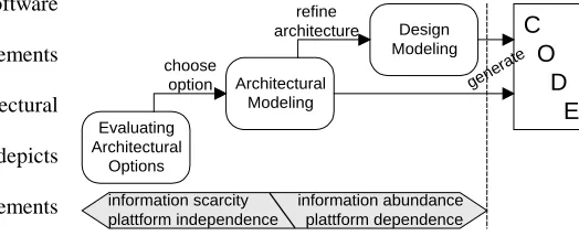
Simply speaking, we see a typical software
development process as consisting of requirements
modeling, evaluation of architectural options, architectural
modeling, designing, and finally coding. Figure 1 depicts
the portion of the process following requirements
engineering, which is the specific focus of this paper.
Evaluating Architectural Options deals with the
exploration of different possible realizations of the requirements. At this level, functional details are not yet (fully)
known. Instead, the focus is on coarse-grain modeling, often also involving outside components like
commercial-off-the-shelf components (COTS) or legacy systems. Analyzing architectural options tends to evaluate the suitability of
components to work together and solve the proposed problem.
Since it would be too expensive to model each architectural option in detail, only a few suitable options should be
selected for further modeling and evaluation. Architectural modeling [6] [5] focuses on modeling the interior workings
and interactions of all to-be-developed parts of a proposed system. Architectural modeling partitions the system into Architectural
Modeling
Evaluating Architectural
Options choose
option
information scarcity plattform independence
Design Modeling refine
architecture
C
O
D
E
information abundance plattform dependence
[image:4.612.279.541.396.503.2]gene rate
coherent subsystems, describes the presumed interactions between the subsystems, and involved external components
and entities (e.g., COTS, humans, etc.). Analyzing architectures focuses on the evaluation of roles and responsibilities of
architectural components as well as their interaction protocols.
Design modeling refines architectural modeling by using lower-level constructs conceptually closer to the
implementation. Thus, the design supplements the architecture by modeling how roles, responsibilities, and interaction
protocols are actually realized. The design typically also extends the architecture by further subdividing architectural
components into smaller pieces and providing additional details for them. Analyzing designs primarily focuses on
evaluating the consistency between the design and its architecture so that the design faithfully realizes the architecture
and is internally consistent.
Our three-tier development approach has a strong emphasis on mismatch detection. Mismatches are introduced
during software development and evolution at various levels while combining (1) models (diagrams) into system
representations and (2) components into systems. In [4] we have shown that component integration and model
integration are two complementary activities. We use components (e.g., libraries, COTS, legacy) as building blocks to
create more complex components or systems. Component-based development decreases subsystem dependency and
increases (component) reuse. Likewise, we use models (diagrams) as building blocks for creating more complex
representations of systems. Model-based development decreases modeling complexity and increases separation of
concerns.
The primary benefits of using our approach to component-based development is the combination of early risk
assessment of mismatches (e.g., incompatibilities) between (OTS) components, the exhaustive modeling of components
(and their interconnections) for detailed mismatch analysis, and the well-defined refinement process for implementing
component wrappers (e.g., “glue code”) and additional functionalities not captured by OTS components. Our approach is
supported by several techniques that, together, cover the three stages of the life-cycle discussed above. Our techniques
also augment one another in their ability to detect larger sets (and more detailed types) of component mismatches.
In the following sections we will discuss the three stages of our component-based development approach. Each
section will describe what information is available at that stage, what are the goals, and what approaches have to be
followed to reach those goals. We will illustrate how mismatches can be identified during each stage in the context of an
3 THE EXAMPLE SYSTEM
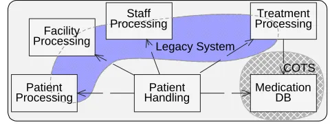
Our proposed example is a Hospital System that extends a legacy application and incorporates some COTS
capabilities. The COTS component Medication DB is a comprehensive database about existing medications and their
side effects. It is used in the Hospital System to automatically identify whether a newly introduced medication for a
patient conflicts with previous or current medications.
The current legacy system covers parts of the
proposed capabilities (see shaded area in Figure 2).
However, the legacy system needs to be extended to
support automated medication analysis. In particular,
elements of the legacy system dealing with patients and
treatments require a more precise definition of their
activities. The legacy system describes treatment information in plain English. For an automated analysis of treatments
and side effects, as well as automated report generation of treatment options and results, the information capture part of
the legacy system needs to be enhanced to do so more systematically.
4 EVALUATING ARCHITECTURAL OPTIONS
Early on, in any software engineering effort, several architectural options may be considered. These are based on the set
of given requirements and must be evaluated, supporting a reduction in the number of options, and then further refined
[7]. These architectural options are high-level descriptions of components and their expected interactions. Among others,
they must be evaluated in order to determine the architectural mismatches that they may entail. The goals described in
this section are to model components with their architectural features and to minimize mismatches between them.
4.1 Finding Conceptual Features to describe Components
The existence of architectural mismatches among various parts of a system may seriously hinder a
component-based software engineering effort [2]. Architectural mismatches are caused by inconsistencies between two or more
constraints of different architectural parts being composed. Architectural mismatches may vary considerably in terms of
the kind of impact they have – some may be easily avoided by the simple use of a wrapper, whereas others may be
extremely expensive to handle. Hence the importance of early risk assessment while considering reuse possibilities.
In order to perform early risk assessment during component composition, we use the Architect’s Automated
Assistant approach and tool (AAA). AAA is a mismatch detection approach that supports rapid evaluations of Patient
Handling MedicationDB Legacy System
COTS
Patient Processing
Treatment Processing Staff
Processing Facility
[image:6.612.301.541.190.281.2]Processing
components with respect to the potential incompatibilities among them. AAA takes as input a high level description of
the (sub)systems to be composed and the kinds of interactions expected among the components in the subsystem. Based
on those descriptions it is possible to infer mismatches among the components. Subsystem descriptions can be given in
terms of architectural styles or specific architectural features. Some of the component features supported by AAA are: 1
• Backtracking – does the component support backtracking while trying to solve a problem?
• Concurrency – is the component multi-threaded or not?
• Control unit – is there a special sub-component within the component responsible for arbitrating which
components are to execute at any given point in time? If so, is this a central control unit or are there distributed
ones?
• Distribution – is the component mapped to more than one hardware node or not?
• Encapsulation – does the component include some private data and/or control elements?
• Layering – does the component use some layering with respect to control or data connectors?
• Preemption – is preemption required in the subsystem? I.e., are there tasks that must be interrupted and
suspended in order to start or continue running another task?
• Reconfiguration – does the component support on-line reconfiguration or does it require off-line intervention?
• Reentrance – A reentrant code can have multiple simultaneous, interleaved, or nested invocations which will
not interfere with each other. Does the component contain reentrant parts?
• Response times – does the component have some predictable, bounded, or unbounded response time
requirements? Is it cyclic (i.e., does it contain a cycle that will run indefinitely)?
• Supported data transfers – how is data transferred within the component? Is it via shared variables, explicit data
connectors (such as pipes), and/or shared repositories?
The various component features are gathered by interviewing the people that were or will be involved in their
development and maintenance. Reengineering existing parts may also be of help, as long as not too much effort is
invested. The same approach is also used for COTS packages, since vendors may be willing to give out at least general
1 Other features supported by AAA and not included here are component priorities, dynamism, and triggering
capabilities. For a detailed description of the complete feature set as well as their relevance for architectural mismatches
information on these characteristics – they do describe the system and often help describe API’s, without giving away
secrets that could reduce the vendor’s competitive advantage. Features whose values are unknown are simply reported as
such.
An architectural style defines a family of systems based on a common structural organization [5]. It constrains both
the design elements and the formal relationships among the design elements [6]. The set of constraints imposed on a
style determine the set of features that are fixed for the style, as well as those that may vary from system to system within
the given style. Consequently, the use of architectural styles simplifies the description task by already inheriting the
values for the features relevant at the style level. Those features not fixed for the style are initially set to unknown and
may potentially be refined as system-specific knowledge becomes available. AAA contains a set of predefined
architectural style descriptions, but allows descriptions of other styles based on their feature set, covering both fixed and
unconstrained values. The set of software connectors (interactions) supported by AAA are calls, spawns (or forks), data
connectors (e.g., pipes), shared data variables, triggers, and shared resources (e.g., a hardware node).
AAA handles partial descriptions of software components due to the fact that it can be used very early in the
software development process, when information is scarce and not yet fully defined. AAA deals with incomplete
information by making pessimistic assumptions while checking for architectural mismatches. Since component
mismatch analysis is done based on assumptions, the results obtained are not precise. However, these results are highly
valuable for risk assessment and provide some insight for later refinement of the previously unconstrained features.
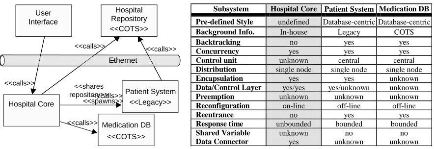
4.2 Detecting Component Mismatches with AAA
In the context of the Hospital System, AAA was given the information depicted in Figure 3. This is a very
high-level architectural model describing the proposed interactions of the existing legacy system (Patient System), COTS
product (Medication DB), and the subsystems under development (Hospital Core, User Interface). The component
Hospital Core is yet to be developed, thus, we do know its set of desirable component features, yet do not want to
over-constrain our options at this point by already committing to an architectural style. Features for the Hospital Core have
been set in AAA according to the description shown in Figure 3. Note that some features, such as control unit and
preemption, have been set as “unknown.” The other components are defined similarly. Note that for brevity we only
listed the features of the most significant component, excluding those of others like User Interface.
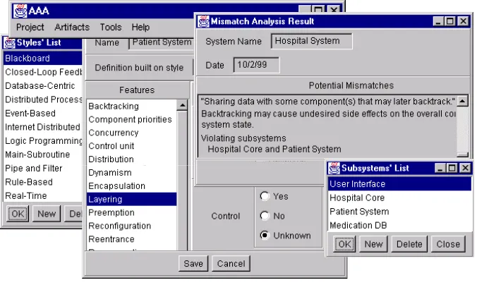
Using the information from Figure 3, AAA can generate a list of potential mismatches . This is done by checking
preconditions and potentially resulting problems that may result from them. A mismatch example would be “This
component is sharing data with some component(s) that may later backtrack”, with the associated precondition that at
least one of the subsystems sharing a given data set has backtracking, and the specific problem of concern being the fact
that, while backtracking, we may have undesired side-effects on the overall system state.
As a result of the AAA analysis, we get an indication of potential risks we might encounter at a later state when
combining those components. AAA, however, comes up short in actually specifying the details of how the components
interaction is enabled and, specifically, how Hospital Core component is actually realized. Here is an excerpt of
mismatches detected by AAA while processing the Hospital System information (we will discuss them in more detail in
the next section):
• A remote connector is extended into or out of a non-distributed subsystem. The originally non-distributed
subsystem(s) cannot handle delays and/or errors occurring due to some distributed communication event
(Violating subsystems: Hospital Core and Patient System, Hospital Core and Medication DB)
• Sharing data with some component(s) that may later backtrack. Backtracking may cause undesired side effects
on the overall composed system state (Violating subsystems: Hospital Core and Patient System)
• Only part of the resulting system automatically reconfigures upon failure. (Violating subsystems:
Reconfiguration on-line: Hospital Core, Reconfiguration off-line: User Interface, Patient System)
• Call to a component that performs on-the-fly garbage collection. Undesirable side effects on the overall
predictable response times (Violating subsystems: Hospital Core and Patient System)
The AAA approach is tool supported. The results obtained while analyzing the information relevant to the Hospital
System can be seen in Figure 4. One of the great advantages of using the AAA tool is the minimal effort required for
obtaining results, as well as experimenting on varying the features and/ or connectors used.
Subsystem Hospital Core Patient System Medication DB Pre-defined Style undefined Database-centric Database-centric
Background Info. In-house Legacy COTS
Backtracking no yes yes
Concurrency yes yes yes
Control unit unknown central central
Distribution single node single node single node
Encapsulation yes yes unknown
Data/Control Layer yes/yes yes/unknown unknown
Preemption unknown unknown unknown
Reconfiguration on-line off-line off-line
Reentrance no yes yes
[image:9.612.93.535.63.215.2]Response time unbounded bounded bounded Shared Variable Data Connector unknown yes no unknown no unknown Hospital Repository User Interface <<COTS>> <<calls>> <<calls>> <<calls>> <<calls>> Hospital Core Medication DB <<COTS>> Ethernet Patient System <<Legacy>> <<shares repository>><<calls>> <<spawns>>
4.3 Minimizing Component Mismatches through Architectural Trade-Off Analysis
The results obtained by analyzing architectural descriptions with AAA must be dealt with by domain and
application experts in order to determine the mismatches that are a real threat and decide how to deal with them. Some of
the approaches that may be used for mismatch risk minimization include but are not limited to: using a different (set of)
component(s) with differing characteristics to support same required functionality, changing the means of components
interaction (connectors), varying the features of the components to be built, and introducing wrappers or instrumented
connectors [8]. All but the last of these approaches are of an exploratory character, hence easily supported by AAA
requiring only a very limited set of actions. The main result of this risk minimization activity is a high level architectural
description reflecting the component configuration that has the most chances of success.
5 ARCHITECTURE MODELING TO INTEGRATE COMPONENTS
The preceding section presented an approach (AAA) whereby a preliminary, coarse-grain model of a system based on its
major components is used to (1) identify one or more viable architectural options for the system and (2) highlight any
unresolved risks associated with each option. These issues are dealt with early in a system’s lifecycle, thus potentially
minimizing the costs of selecting suboptimal options or failing to mitigate the major risks. However, the AAA approach
by itself does not provide the mechanisms needed to perform in-depth comparisons of identified options or to resolve the
risks. Instead, AAA must be accompanied by additional approaches that will, for each architectural option,
(1) Find an architectural style that supports the system’s current components, their conceptual features, and their
interactions (recall the discussion in Section 4). Certain styles may be better suited than others to handle particular
[image:10.612.129.467.67.269.2]evaluation of architectural options. Additionally, an architect must ensure that styles do not clash with system
requirements exacerbate other known risks. Finally, it may be difficult to assess the impact of a style and the
architectural model on a given issue, in which case, any decision must be deferred pending additional modeling and
analysis (e.g., as proposed in Section 6);
(2) Assess the ability of the chosen style to help minimize the mismatches between those components, features, and
interactions;
(3) Carefully model the critical aspects of the system in the chosen style, e.g., by using an architecture description
language (ADL) [9]; and
(4) Analyze the architectural model for model mismatches. Note that these mismatches will typically differ from those
identified by AAA since the architectural model will be more detailed and complete.
5.1 Finding Architectural Style to fit Components
Architectural options, as found through AAA in Section 4, come up short in specifying how components have to be
built (or wrapped in the case of OTS) and how they must interact. In order to refine a given architectural option into an
eventual implementation, one has to define the components, connectors, and their interconnections (guided by the rules
of a given style) in a more rigorous manner. All software systems adhere to some architectural style. Common styles
include layered, client-server, pipe and filter, event-based, and main-subroutine [5] [10]. An architectural style defines
the relationships of components and connectors that are shared across systems. Choosing an (in)appropriate architectural
style(s) has considerable impact on the feasibility of a project. Our method provides help in this regard. For clarity, the
method is illustrated in the context of the Hospital System example.
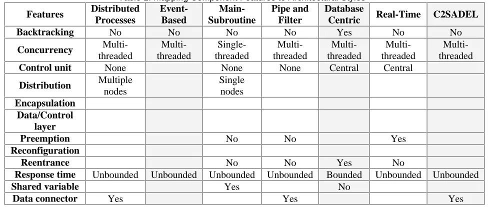
Table 1 couples the notion of component features (Section 4) and styles, showing their relationship (A more
complete version of the table is given in [11]). The table can be used as a selection mechanism to infer candidate styles
out of known components, connectors, and their configurations. For example, although the Hospital Core component in
the Hospital System currently has no style explicitly associated with it, its conceptual features exclude many potential
styles. From Figure 3, we know that Hospital Core must support concurrency. We learn from Table 1 that all of the
considered styles, except for main-subroutine, support concurrency. The main-subroutine style should therefore not be
used as an architectural style in this case. This exclusion method can be applied in context of all other features.
Further analysis establishes that, of the four major components in our case study, two follow the database-centric
unspecified (Hospital Core). In choosing an architectural style for the overall system, we must also choose an
architectural style that fits all components and their proposed forms of interactions.2 In this case, all components are
currently defined as non-distributed, i.e., each individual component resides in a single address space. By itself, this
property does not place any constraints on the configuration of the entire system, meaning that all styles remain in the
candidate pool. Because of the need for concurrent components, the overall system must also be concurrent (excluding
the main-subroutine style again). Since some components require reentrance and others do not, we must use a style that
supports both (excluding pipe-and-filter and real-time). Finally, since some components require a central control unit, all
styles not supporting such a unit may be excluded as well (e.g., distributed processes).
With the remaining three styles—event-based, database-centric, and C2—we encounter a conflict. On the one hand,
system response time needs to be unbounded due to the Hospital Core component. On the other hand, backtracking
capabilities are needed to support the Patient System component. The former favors the event-based or C2 styles,
whereas the latter favors the database-centric style. To resolve this conflict, we either need to investigate additional
styles or use additional information:
2 Note that it is indeed possible to select multiple architectural styles for different parts of a given application. Our
approach allows this, in the same manner as discussed above, assuming the styles are inherently compatible.
[image:12.612.70.551.79.287.2] [image:12.612.64.553.80.287.2]Architectural style incompatibilities [34] are beyond the scope of this work.
Table 1. Mapping Component Features to Architectural Styles
Features Distributed Processes
Event-Based
Main-Subroutine
Pipe and Filter
Database
Centric Real-Time C2SADEL
Backtracking No No No No Yes No No
Concurrency
Multi-threaded
Multi-threaded
Single-threaded
Multi-threaded
Multi-threaded
Multi-threaded
Multi-threaded
Control unit None None None Central Central
Distribution Multiple
nodes
Single nodes
Encapsulation Data/Control
layer
Preemption No No Yes
Reconfiguration
Reentrance No No Yes No
Response time Unbounded Unbounded Unbounded Unbounded Bounded Unbounded Unbounded
Shared variable Yes No
1) To choose between event-based and C2, we may choose the one with the greatest feature coverage: In this case, the
example favors the C2 style since it supports explicit data connectors as required by the Hospital Core component
(C2 is an event-based styles with exactly that extension).
2) To choose between C2 and database-centric, we may choose the one with the highest potential for resolving known
architectural mismatches (or risks) as they were identified in Section 4. To address the remote connector mismatch,
C2-style connectors limit the effects of individual components on overall system structure and evolution. C2
components exhibit very low coupling: a component is only aware of a single connector above and/or a single
connector below it. That means that components can be added, removed, replaced, or reconnected in a C2-style
architecture, even at runtime, without their neighboring components ever needing to know about those changes [12].
One the other hand, the database-centric style is not well suited to this case. Conversely, the database-centric style is
well suited to address the sharing data and component backtracking mismatch, for which C2 is not as well suited.
The automatic reconfiguration mismatch is addressable by C2: the message-based interaction of C2 components via
connectors presents an ideal foundation for system adaptability, both off-line and at system runtime [12]. It is
important to note that the fourth mismatch discovered by the AAA tool—response time due to on-the-fly garbage
collection—is neither well supported by C2 nor by the database-centric style.
As will likely often be the case, none of the three styles is the perfect fit to this problem. In such a case, the
selection of a style is based on an evaluation of which style can be most easily amended to address its deficiencies. If the
selected architectural options simply cannot be implemented by any of the candidate styles, another option should be
chosen. If no architectural option can be satisfied, then this may indicate a need for a change in the requirements.
Specifically, in the case of the hospital application, C2 can be amended to deal with the backtracking issue. The
topological rules and message-based communication of C2 support easy update of components. In particular, if the
Patient System component from Figure 3 backtracks, it can send a message to that effect to the Hospital Repository; in
turn, the Repository will issue a notification message, which will be relayed by the appropriate connector(s) to the
Hospital Core component. Note that Hospital Repository is a COTS component and, as such, is unlikely to adhere to
C2’s interaction rules. However, C2 provides a set of simple mechanisms and resulting tools for incorporating
heterogeneous, OTS components [13]. In particular, a light-weight wrapper can be constructed for Hospital Repository,
The next section will, therefore, model in more detail the chosen architectural option from Section 4 using the C2
style and its accompanying suite of modeling, analysis, and implementation technologies. The goal of the further
analysis is to investigate in more detail whether the above shortcoming can be mended and whether there are other,
currently unknown risks. We will also briefly discuss the potential role of other architectural technologies as candidates
for effecting additional architectural styles (e.g., layered, event-based, database-centric).
5.2 Modeling the Hospital System in C2SADEL
In this section we discuss the approach to leveraging an architectural style (C2) and using an ADL (C2SADEL) to
further refine (or define) the component and connector features that were not elucidated as part of the process of
evaluating architectural options (Section 4). An explicit architectural model allows for mismatches to be detected at the
level of component interfaces, behaviors, and interaction protocols. Explicit models are also amenable to analysis tools
that support rapid evaluations of architectural descriptions and highlight key problem areas in a given system’s model.
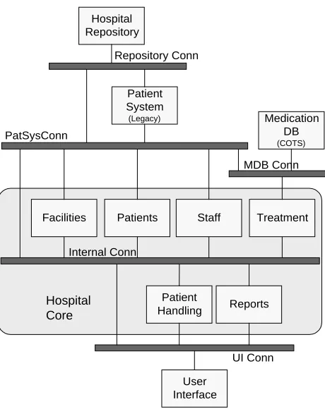
The C2-style breakdown of the Hospital System architecture is shown in Figure 5. The shaded portion in the center
of the architecture represents a refinement of the Hospital Core component from Figure 3. C2 allows Hospital Core to be
modeled as a single component or, hierarchically, to contain an internal architecture of its own.
Recall from Section 4 that the reengineered hospital
system will include components that supplement the
architecture functionality already provided by one or more
of the legacy components. Thus, for example, the Patients
component in Hospital Core will supplement the legacy
Patient System component. The Patient Handling
component will issue patient handling messages. In turn,
those messages will be routed by the appropriate
connector(s) to one of the two patient processing
components (e.g., based on their interfaces). Occasionally,
Patient Handling will issue patient treatment related
messages to the Treatment component, which will, in turn,
consult the COTS Medication DB component to determine,
e.g., any conflicts in prescribed medications. Similarly, the
Patient Handling
Medication DB
(COTS)
Staff Patients
Facilities Treatment
Patient System
(Legacy)
User Interface
Reports
Hospital Core
Hospital Repository
PatSysConn
Repository Conn
MDB Conn
Internal Conn
[image:14.612.319.549.393.683.2]UI Conn
Facilities and Staff components will handle their respective responsibilities, while the Reports component will invoke
any of the components above it needs to produce a report the user demands via the User Interface component. The
Hospital Core and Patient System components may store some information internally, or they may occasionally request
information from a central, COTS Hospital Repository.
The diagram shown in Figure 5 gives us good understanding of the “big picture,” i.e., the hospital system’s overall
architectural breakdown. However, in order to ensure that the architecture exhibits the desired properties and that the
different components can interact in envisioned ways, a more detailed and formal specification of the architecture is
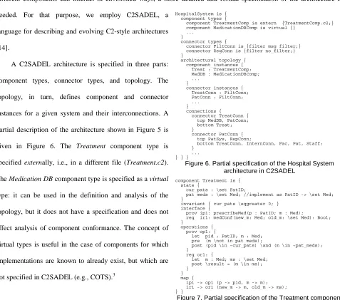
needed. For that purpose, we employ C2SADEL, a
language for describing and evolving C2-style architectures
[14].
A C2SADEL architecture is specified in three parts:
component types, connector types, and topology. The
topology, in turn, defines component and connector
instances for a given system and their interconnections. A
partial description of the architecture shown in Figure 5 is
given in Figure 6. The Treatment component type is
specified externally, i.e., in a different file (Treatment.c2).
The Medication DB component type is specified as a virtual
type: it can be used in the definition and analysis of the
topology, but it does not have a specification and does not
affect analysis of component conformance. The concept of
virtual types is useful in the case of components for which
implementations are known to already exist, but which are
not specified in C2SADEL (e.g., COTS).3
3
Medication DB is modeled as a virtual component in this case only to demonstrate this feature of C2SADEL. A typical approach to modeling
COTS components has been to extract from their available documentation (e.g., API) the desired services and model them in C2SADEL, thus enabling
more meaningful component conformance analysis.
HospitalSystem is { component_types {
component TreatmentComp is extern {TreatmentComp.c2;} component MedicationDBComp is virtual {}
... }
connector_types {
connector FiltConn is {filter msg_filter;} connector RegConn is {filter no_filter;} }
architectural_topology { component_instances { Treat : TreatmentComp; MedDB : MedicationDBComp; ...
}
connector_instances { TreatConn : FiltConn; PatConn : FiltConn; ...
}
connections {
connector TreatConn { top MedDB, PatConn; bottom Treat; }
connector PatConn { top PatSys, RepConn;
bottom TreatConn, InternConn, Fac, Pat, Staff; }
[image:15.612.69.546.218.639.2]... } } }
Figure 6. Partial specification of the Hospital System architecture in C2SADEL
component Treatment is { state {
cur_pats : \set PatID;
pat_meds : \set Med; //implement as PatID -> \set Med; }
invariant { cur_pats \eqgreater 0; } interface {
prov ip1: prescribeMed(p : PatID; m : Med);
req ir1: medConf(new_m: Med; old_m: \set Med): Bool; }
operations { prov op1: {
let pid : PatID; m : Med; pre (m \not_in pat_meds);
post (pid \in ~cur_pats) \and (m \in ~pat_meds); }
req or1: {
let m : Med; ms : \set Med; post \result = (m \in ms); }
} map {
ip1 -> op1 (p -> pid, m -> m); ir1 -> or1 (new_m -> m, old_m -> ms); } }
Individual components, such as Treatment shown in Figure 7, are specified to contain a set of component state
variables, a component invariant, and a set of services. Each service comprises an interface and an operation; operations
are modeled via pre- and post-conditions in first-order logic. A service can be provided by the modeled component or
required of some other component in an architecture. Finally, interfaces and operations are separated, so that it is
possible for an operation to export multiple interfaces.
5.3 Minimizing Component Mismatches through Architectural Analysis
The specification of component invariants and services in C2SADEL allows components that are composed in an
architecture to be analyzed for conformance. For example, the required medConf service of the Treatment component
must be matched by a provided service of one of the components to which Treatment is attached in the hospital system
architecture. More specifically, due to C2’s style rules, this service must be matched by one of the components above
Treatment in the architecture, namely Medication DB, Patient System, or Hospital Repository. A required service P
matches a provided service Q if the following conditions hold [15]:
• P and Q have identical interface and interface parameter names;
• either both P and Q have a return value or neither does;
• the types of P’s interface parameters are subtypes of the types of Q’s interface parameters;
• the type of P’s return value is a supertype of the type of Q’s return value;
• P’s precondition implies Q’s precondition; and
• Q’s postcondition implies P’s postcondition.
At a minimum, these rules ensure that, if, e.g., procedure calls are used to enable the interactions of the
implementations of the components containing P and Q, those interactions will be allowed by the underlying
programming language. Additionally, the analysis of pre- and postconditions allows us to establish the behavioral
conformance of the two components. Since manual conformance checking would be a time consuming and error prone
task, we use the SAAGE environment to perform automatic model checking of an architecture. Furthermore, SAAGE
supports automated generation of the architecture’s prototype implementation [14]. The prototype allows observation
and rapid evaluation of critical dynamic system properties.
Once the software architect is satisfied that the modeled architecture exhibits the desired properties, (s)he can use
SAAGE to generate a Unified Modeling Language (UML) model of the architecture [16] [17] and, subsequently, refine
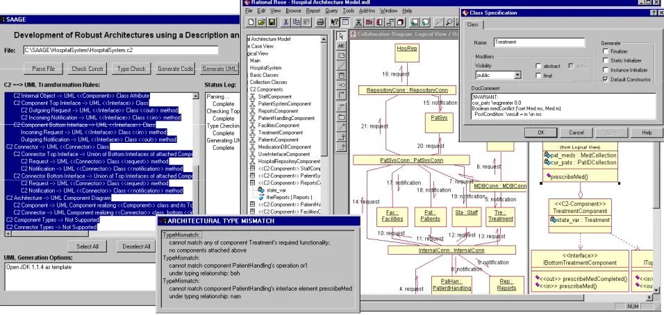
Figure 8 shows a screenshot of SAAGE and the results of its analysis of the hospital system specified in
C2SADEL. The figure also shows the resulting UML model automatically generated in Rational Rose. Note that
SAAGE reported three mismatches in the “Architectural Type Mismatch” pane. The first mismatch states that the
Treatment component’s required service medConf cannot be matched because no components are attached above it. In
this case, this simply means that all components attached above Treatment in the hospital system architecture, such as
Medication DB, are virtual and SAAGE was unable to use them to establish component conformance.
The second mismatch is more interesting: it indicates that SAAGE was able to successfully match the interface of
Patient Handling component’s required service prescribeMed to Treatment’s corresponding provided service. However,
the required behavior does not match the provided behavior. The pre- and postconditions of the two operations are
specified in the table below.
Patient Handling req service
Treatment prov service
pre (p \in pats) pre (m \not_in pat_meds) post (m \in ~meds) post (p \in ~cur_pats)
\and (m \in ~pat_meds)
To satisfy behavioral conformance rules, the following two relationships must hold:
• req precondition implies prov precondition, i.e.,
(p \in pats) => (m \not_in pat_meds)
[image:17.612.175.436.569.626.2]• prov postcondition implies req postcondition, i.e.,
(p \in ~cur_pats) \and (m \in ~pat_meds) => (m \in ~meds)
The first relationship clearly cannot be established: the left hand side (LHS) of the implication deals with patients
and the right hand side (RHS) with medications. The second relationship is of the form A and B => A, which is always
true. To enable the match of the postconditions, SAAGE had to unify the RHS variable meds, which is of the generic
type STATE_VARIABLE [15] [14], with the LHS variable pat_meds, which is defined as part of the Treatment
component’s state (recall Figure 7).
Since the necessary relationship between the preconditions could not be established, SAAGE also attempts to
match Patient Handling component’s required service prescribeMed to the provided services of the other components
attached above it in the hospital system architecture. None of the other components provide a corresponding service,
resulting in the third architectural type mismatch shown in Figure 8. Finally, note that the architect’s decision to generate
the UML model in spite of the mismatches indicates the architect’s belief that those mismatches are either not critical or
would be remedied during the system’s design phase.
5.4 Applicability to Other Styles and ADLs
The above discussion demonstrated the coupling of AAA and C2, two techniques independently developed by the
authors. However, our overall approach to exploiting architectures to aid component mismatch detection is in no way
predicated upon the use of C2. Quite the contrary, the same general process can be used when other styles and ADLs are
coupled to aid in software modeling and analysis [9]. For example, the event-based style may be effectively used in
conjunction with the Rapide ADL [18]; similarly, the layered style may be used with the GenVoca ADL [19]; and the
distributed style may be coupled with Darwin [20]. Finally, certain ADLs, such as Aesop [21] and Wright [22], allow an
architectural style to be formally modeled using the same environment and language that is, in turn, used to model
application architectures within that style. In each such situation, the details of the models and analyses depend upon the
characteristics of the style and features and tool support of the chosen ADL.
6 DESIGN MODELING AND REFINEMENT INTO CODE
The process of choosing an architectural option, selecting its architectural style, and modeling the resulting
architecture in detail yields an architectural model. At this stage, we have available a fairly well validated architectural
model of components, connectors, and their combined configurations of which we know that they exhibit properties that
refinement involves: (1) the implementation of components that are not off-the-shelf; (2) the implementation of glue
code (e.g., wrappers) around components that are pre-existing (e.g., COTS or legacy); and (3) the implementation of
connectors that enable components to interact (unless they are COTS themselves like in CORBA [23]).
The traditional way if implementing software models of any kind is the manual process of reading and interpreting
available documentation followed by programming it. With the availability of architectural models, the task of
refinement is simplified in that major components are specified; those components provide the major partitions of a
system and programming those partitions is less complex in that they can be implemented separately. The downside of a
manual development approach is in its manual nature where there are no guarantees that the model descriptions are
implemented correctly. Refinement from architectures into code must however ensure consistency. In [24], we have
investigated the issue of consistency among model descriptions and have found that its major cause is information
discontinuities among models where information specified in one model cannot easily be transitioned into the other in an
automated manner (e.g., from architecture to code). In [25], we further found that this discontinuity among models can
be dealt with by employing automated synthesis and analysis.
Synthesis enables one to generate a new model (e.g., code) from an existing model (e.g., architecture), while
analysis provides mechanisms for ensuring the preservation of certain properties across (independently created) models.
Software engineers extensively employ both kinds of techniques. For example, program compilation involves both the
analysis of the syntactic and semantic correctness of one model (source code) and the synthesis of another model from it
(executable image). Synthesis and analysis techniques span a spectrum from manual to fully automated. Manual
techniques tend to be error prone, while fully automated techniques are often unfeasible [26]. Furthermore, in some cases
one technique (e.g., analysis) is easier to perform than another (synthesis). For this reason, one typically has to resort to
using some combination of synthesis and analysis techniques of varying degrees of automation when ensuring
inter-model consistency. In the following, we will discuss synthesis and analysis in context of architectural inter-models.
6.1 Synthesizing a Design from an Architecture
The synthesis process for refining architectures may vary depending on the different architectural styles available
(e.g., event-based, main-subroutine, C2, etc.). Our example mandates the refinement of a C2 style, however, if we had
chosen another type of style, we would require a different refinement technique. For our purposes, the starting point of
architecture adheres to some architectural style (e.g., client-server, pipe-and-filter, layered) and its representation may be
formalized using an architecture description language.
Refining the architecture into code would be the most straightforward approach, however, it can often not be done
directly. We therefore use design languages such as the Unified Modeling Language (UML) [3] as intermediate models
for refinement. Using a generic-purpose notation like UML for refinement has four major advantages: (1) refining into
design models instead of code is less of an gap to bridge and thus easier; (2) design languages are generally easier
understandable which makes subsequent non-automatable refinement simpler; (3) design specifications provide
additional, more program-language-specific constructs that might increase the degree of (automated) code generation;
and finally (4) design modeling can make use of design patterns, such as wrapper technologies, which in turn increases
the degree of reuse.
Based on our example in C2SADEL, the SAAGE environment is capable of generating a partial implementation of
its architecture [14]. At the same time, many lower-level issues (e.g., any additional processing and data objects, specific
data structures, and algorithms) that are needed to complete that implementation are not provided at the architectural
level. For that reason, the “outer skeleton” of the application generated from the architectural model is complemented
with the details typically provided through general-purpose design activities. [16] discusses in detail what is involved in
refining architectural descriptions into UML where different refinement scenarios are presented. It is also shown how
transformation from C2SADEL to the intermediate UML model is enabled by a set of specific refinement rules. Those
refinement rules make sure that the refined architecture still reflects the structure, details, and properties of the
architectural model, thus guaranteeing consistency between the architecture and design. The Rational Rose screen snap
shot in Figure 8 (right half) depicts the refined hospital example using UML. UML objects are used to represent
architectural instances and UML classes are used to define their interfaces.
We have conducted an in-depth study of the feasibility of mapping ADLs to UML [17]; this study involved three
representative ADLs (C2SADEL, Rapide [18], and Wright [22]). Furthermore, related works of other researchers have
done similar things for other types of ADLs and architectural styles (e.g., [27] for a specific type of layered style, [28]
for real-time styles, [29] for object-oriented and main subroutine styles, or [30] for styles that can be modeled via
proof-carrying architectures). Those works demonstrate that other types of architectural styles can be refined into code, either
refinement based on architectural styles. All those refinement techniques reduce manual labor but have one major
deficiency – they only guarantee consistency initially.
6.2 Analyzing Consistency between Architectures and Refinements
Model analysis extends synthesis by also ensuring that the architecture and all its refinements remain consistent
after their creation. The basic problem is that after the synthesis of design and code, all models (architecture, design, and
code) may be altered concurrently. For instance, since 100% automated code generation out of architectural descriptions
is rare, additional manual programming is required to complete the code – a task that may introduce inconsistencies.
Furthermore, it is possible that the architectural or design information change even after coding has commenced. Those
architecture and design changes must be validated against one another and against the source code to ensure their
continuing consistency.
We therefore have developed a view integration
approach to ensure continued consistency of models
throughout the refinement process – even if models are
changed due to evolutionary considerations. Our view
integration framework approach [31] [24] exploits the
redundancy between models: for instance, if model A
contains information about model B, this information can be
seen as a constraint on B (e.g., as this is the case between
the architecture in Figure 5 and the design in Figure 9). Our
view integration framework is used to enforce such
constraints and, thereby, the consistency across views. In
addition to constraints and consistency rules, our view integration framework also defines what information can be
exchanged and how information can be exchanged. This is critical for a scalable and automated mismatch identification
and resolution process.
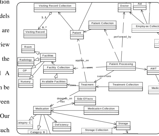
Figure 9 shows an excerpt of the design refinement of our hospital system using a UML class diagram model. At
this point, we can assume that the automatically generated design was manually refined potentially negating consistency.
The basic question now is whether the depicted UML class diagram is still consistent with the original C2 architecture.
We distinguish between structural consistency and behavioral consistency. Structural consistency ensures that the Treatm ent C ollec tion
C atego ry B C ategory C
AW T
Medic ati Aid D oc tor
Em ploy ee C ollec tion
Vis iting R ec ord
Patient C ollec tion Vis iting R ec ord C ollec tion
0..* 1..1 0..* 1..1 Patient Av R oom OP R adiology
N urs ery
Storage C ollec tion Side Ef f ec ts
D ef ic ienc y Storage
Medic ation has
Medic atio n C olle ction Treat ment
Patient Proc es s ing F ac ilities
F ac ility C ollec tion
s uperv is es perf orm ed_by
Av ailable F ac ilities
depends _on applies _on
[image:21.612.290.546.303.522.2]us es us es
interfaces provided through C2 component and connectors are equivalent to those provided through UML classes.
Basically, C2 components and connectors may be seen as the interfaces for compact, self-sustaining sections of the
implementation. Since C2 elements are often coarse-grain, it is reasonable to assume that a collection of classes is
[image:22.612.288.549.166.361.2]needed to implement a single C2 element.
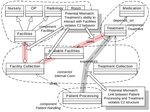
Figure 10 shows a piece of the UML design
model depicting the relationships between Patient
Processing, Treatment, and Facilities. The dashed
lines around classes indicate mappings between C2
elements and design elements. For instance, the
classes Facilities Collection, Available Facilities and
Treatment Collection are part of the C2 connector
Internal Conn linking Patient Handling with
Treatment and Facilities (recall Figure 5). Note that
this figure is simplified in that not all classes are
shown. Analyzing Figure 10, it can be seen that the dependency relationship between Patient Processing and Treatment
is in violation with the C2 architectural structure: no corresponding link between Patient Handling and Treatment can be
found in the C2 architecture shown in Figure 5.
Even if we were to correct the above problem, ensuring structural consistency between design and architecture does
not guarantee proper behavior of the design. For instance, a C2 behavioral constraint states that no two components of
the same level are allowed to interact; instead, C2 interactions go strictly up and down. In Figure 10 we can also see a
potential violation of that constraint. The class Treatment depends (uses) on the class Available Facilities, which, in turn,
depends on the class Facility Collection. This, in itself, is not a mismatch since both classes are part of Internal Conn
connector and a corresponding link exists in C2. However, Available Facilities can only access the classes Facility
Collection and Facilities, the latter being another
component at the same level as Treatment. Given
the current design knowledge, it is possible for
Treatment to interact with Facilities, which is a
behavioral violation of C2.
connector Internal Conn component Patient Handling component Treatment component Facilities Room OP Radiology Nursery Medication Treatment Treatment Collection Patient Processing Facilities Facility Collection
Availab le Facil ities
depends_on
uses
supervises
us es
Potential Mismatch: Link between Patient Processing and Treatment
violates C2 structure Potential Mismatch:
Treatment’s ability to interact with Facilities violates C2 behavior
Figure 10. Mismatches between C2 and UML
Treatment Available Facilities Facility Collect ion Facilities
Treatment Facilities
Treatment
Available Facilities
[image:22.612.274.548.604.695.2]Facilities
The above example is trivial enough for a human to identify the design mismatches with relatively little effort. The
UML/Analyzer tool [24] supports the consistency checking of much more complex cases. Two factors add to the
complexity here: 1) the existence of ‘helper classes’ in the design and 2) the number of classes and possible interactions.
UML/Analyzer uses an abstraction technique to eliminate helper classes [32]. For instance, to identify the behavioral
mismatch in Figure 10, we need to eliminate the helper classes Available Facilities and Facility Collection that ‘obstruct’
our view of the direct relationship between Treatment and Facilities. In this particular example, UML/Analyzer sees a
dependency to from Treatment to Available Facilities followed by a generalization (inheritance) from Available
Facilities to Facility Collection; this is, in turn, followed by an aggregation from Facilities to Facility Collection (Figure
11 top row). The tools’s abstraction method then uses its abstraction rules (some depicted in Figure 12 upper right) to
eliminate helper classes. The UML/Analyzer tool finds a dependency relationship between Treatment and Facilities after
two subsequent transformations (Figure 11). This tool and underlying model can be applied to arbitrary complex class
patterns. Figure 12 depicts screenshots of the UML/Analyzer tool. Currently only class diagrams and C2 diagrams are
fully supported. This work is being extended on other types of UML diagrams as well as other architectural description
[image:23.612.66.548.406.673.2]languages.
Like in the previous section, the approach to consistency analysis varies depending on the architectural styles
chosen. In [4] we discuss consistency checking issues that apply to layered styles and pipe-and-filter styles. Real-time
styles and their refinement are discussed in [33].
7 DISCUSSION
Our proposed approach “interfaces” with requirements engineering on one side and implementation on the other.
Requirements modeling needs feedback to evaluate the feasibility of suggested options. If it takes weeks or months to
give that feedback, system requirements modeling may never stabilize or artificial cut-off dates must be set with negative
side effects onto flexibility (e.g., waterfall model). If, on the other hand, the feedback can be obtained in days,
requirements modeling intertwined with architectural modeling becomes feasible. Our approach provides feedback about
unfeasible options in mere hours; in turn, we can select promising options and refine them into architectures for more
thorough risk analysis in days or weeks.
We believe that it is very beneficial to combine model-based and component-based development since model
descriptions provide the context for how to combine components, whereas components address more specific system
needs. Furthermore, components are helpful in partitioning architecture and design models: since components represent
independent subsystems, any resulting models tend to become more independent themselves. Our proposed three-tiered
development approach combines modeling constructs and processes that were previously separated.
The power of compositional modeling techniques provided through AAA and SAAGE lies in the fact that major
development concerns can be modeled, analyzed and simulated early on, resulting in a very cost effective way of dealing
with development risks. However, as discussed earlier, those models add little value to the final software product if the
product-related information stored in them cannot be transitioned into the final product. For instance, we chose the C2
architectural style because the AAA analysis suggested that there are potential risks that C2 could remedy (e.g., remote
connector). To ensure that the final product still resolves those risks, we need to also verify that the final product
inherited all relevant characteristics from its C2 architecture. In other words, we need to ensure consistent refinement.
Since the example we chose in this paper is not representative for all software products, we also discussed how
other types of situations could be addressed via our approach. In order to summarize the big picture of our proposed
development approach, consider Table 2. The table shows the three major elements of our development approach
(columns) and their properties. The table briefly summarizes the constructs we have available at those respective stages,
approaches one has available, and the tools that support it. The table has been extrapolated from the discussion provided
in the previous sections. It represents a quick reference for assessing the issues, progress, and results in a
[image:25.612.68.549.77.588.2]component-based development effort.
Table 2. Impact of our Component-Based Development Approach
Modeling Architectural Options Modeling Architecture Modeling Design and Coding
Modeling Constructs
• Components
• Interactions
• Conceptual features
• Architectural configuration
• Architectural styles
• Roles and responsibilities
• Classes
• Methods
• Variables
Questions
• What are the components required to do?
• Can we exclude potentially unfeasible architectural options?
• What are the component characteristics?
• How can architectural options be modeled and analyzed without implementing it?
• Does the architectural solution satisfy requirements?
• How can architectural model be implement?
• How are configurations, styles, roles, and responsibilities transformed into programming constructs?
Timeframe • Can frequently be done in hours for complex systems
• Can frequently be done in days or weeks for complex systems
• Frequently takes many months or even years in complex systems
Given
• requirements
• domain Knowledge
• COTS and legacy components
• one or more viable architectural options based on components
• known risks from previous stage that were not resolved
• one or more viable architectural models that satisfy requirements
• known risks from previous stages that were not resolved
Goals
• find components that could satisfy requirements (with or without overlapping functionalities)
• minimize mismatches between those components
• find an architectural style that supports components, their conceptual features, and their interactions
• minimize the mismatches than could occur between those components, features, and interaction with the respective chosen style (note: some styles may be more suitable than others in handling known mismatches)
• consistently refine architectural model into code
• use of design language as intermediate model if necessary (e.g., to enable design pattern reuse)
Approaches
• vary components to minimize potential risks (e.g., replace event-based component with blackboard-style component)
• vary component interactions (connectors) to minimize potential risks
• toggle variable component characteristics (e.g., of to-be-built subsystems)
• evaluate different architectural styles to investigate their potential impact
• refine (define) undeclared component and connector features to tailor integration between styles, components, and connectors.
• refine known style, component, and connectors information into code
• refine known style, component, and connectors information into design information
Tools
tradeoff analysis tool that supports rapid evaluations of components
with respect to potentially incompatibilities among them
• selection mechanism that infers styles out of known component and connector characteristics
• tradeoff analysis tool that supports rapid evaluations of architectural descriptions between styles, components, and connectors
8 CONCLUSION
This paper discussed three modeling and analysis approaches dealing with the “upstream” activities in the software
engineering life cycle: architectural options, architectures, and designs. We used an example to illustrate their respective
advantages in identifying and resolving mismatches. We also showed how (mismatch) feedback from one could impact
others and drive development decisions.
Our technique on evaluating architectural options may yield useful feedback (e.g., risk assessments) within hours
and is highly useful for eliminating infeasible options early on (e.g., even during requirements negotiations), however, at
the expense of precision. Our technique on architectural modeling is complementary since it is capable of performing
more detailed and precise component mismatch analyses, however, at the expense of the effort required. Both are needed
to rapidly develop component-based software, and thus, both have to be connected. To that extend, we defined
mechanisms for information sharing among our technique. Additionally, we found techniques on how to systematically
refine architectures (with their incorporated component definitions) into more detailed architectures, designs and code.
We believe that mismatch detection should happen as early on as possible. One software engineering truism is that
the longer a mismatch remains undetected the more harm it might cause. We also believe that automated analysis
techniques are invaluable in getting easy and fast initial feedback on potential problems and challenges regardless of the
current development stage. We have shown that our techniques are useful as early on as the initial system analysis stage,
where the lack of information drives development. We have also shown that our techniques can be used as late as coding
and maintenance, when information abundance constitutes key complexities.
We are continuously working on our tool support in three primary directions: 1) more extended coverage of other
development models such as architectural description languages and design models; 2) more complete data, control, and
process integration between our tools; and 3) more comprehensive coverage of the software-lifecycle (e.g., product
families, requirements engineering, reuse).
ACKNOWLEDGEMENTS
This research is partially sponsored by the Defense Advanced Research Projects Agency, and Air Force Research
Laboratory, Air Force Materiel Command, USAF, under agreement numbers F30602-94-C-0195 and
F30602-99-C-0174, and by the Affiliates of the USC Center for Software Engineering. This material is also partially based on work
supported by the National Science Foundation under Grant No. CCR-9985441. The U.S. Government is authorized to