City, University of London Institutional Repository
Citation
:
Kloukinas, C. and Ozkaya, M. (2012). Xcd - Modular, Realizable Software
Architectures. Lecture Notes in Computer Science: Formal Aspects of Component Software,
7684, pp. 152-169. doi: 10.1007/978-3-642-35861-6_10
This is the unspecified version of the paper.
This version of the publication may differ from the final published
version.
Permanent repository link:
http://openaccess.city.ac.uk/2886/
Link to published version
:
http://dx.doi.org/10.1007/978-3-642-35861-6_10
Copyright and reuse:
City Research Online aims to make research
outputs of City, University of London available to a wider audience.
Copyright and Moral Rights remain with the author(s) and/or copyright
holders. URLs from City Research Online may be freely distributed and
linked to.
X
C
D – Modular, Realizable Software Architectures
∗
Christos Kloukinas and Mert Ozkaya
School of Informatics City University London London EC1V 0HB, U.K.
{c.kloukinas,mert.ozkaya.1}@city.ac.uk
Abstract. Connector-Centric Design (XCD) is centred around a new formal ar-chitectural description language, focusing mainly oncomplex connectors. In-spired by Wright and BIP, XCD aims to cleanly separate in amodularmanner the high-levelfunctional,interaction, andcontrolsystem behaviours. This can aid in both increasing the understandability of architectural specifications and the reusability of components and connectors themselves. Through the independent specification of control behaviours, XCD allows designers to experiment more easily with different design decisions early on, without having to modify the func-tional behaviour specifications (components) or the interaction ones (connectors). At the same time XCD attempts to ease the architectural specification by follow-ing (and extendfollow-ing) a Design-by-Contract approach, which is more familiar to software developers than process algebras like CSP or languages like BIP that are closer to synchronous/hardware specification languages. XCD extends Design-by-Contract(i)by separating component contracts into functional and interac-tion sub-contracts, and(ii)by allowing service consumers to specify their own contractual clauses. XCD connector specifications are completely decentralized, foregoing Wright’s connector glue, to ensure their realizability by construction.
Keywords: Software architecture; Modular specifications; Separation of func-tional interaction and control behaviours; Design by contract; Connector realiz-ability.
1
Introduction
Architectural descriptions of systems are extremely valuable for communicating high-level system design aspects and the different solutions that have been evaluated for meeting system-wide, non-functional properties. The need for components and con-nectors to be first-class architectural entities has been advocated from the very begin-ning [15, 30]. However, support for complex connectors is minimal in languages used more widely by practitioners currently, e.g., AADL [13], SysML [6]. These rely mostly on simple interconnection mechanisms like procedure-calls and provide no support for specifying complex connectors, focusing their attention mostly upon components. The end result is that architectures end up more like low-level designs [11].
With minimal support for connectors, components have to incorporate specific in-teraction protocols, thus reducing their reusability. Worse yet, when component specifi-cations omit to specify explicitly which protocols they have been designed for, we have the problem of “architectural mismatch” [14], i.e., the inability to compose seemingly compatible components, due to the (undocumented) assumptions these make on their interaction with their environment. In quite a few cases designers are supposed to use specific components that act as connectors in order to represent complex connectors. This hinders analysis, as it is not possible to identify automatically which components represent components and which ones represent connectors. It also places a lot of re-sponsibility upon designers for ensuring that the architectural abstraction constraints are respected. It is similar to trying to encode some O-O features by hand in C – possible but very difficult to get (and keep. . . ) correct. In our view the main value of software architectures is to enable early formal system analysis and not to be used for code gen-eration alone. As such, an ADL needs to cleanly represent the various entities, in order to aid the automation of architectural analysis.
The Connector-Centric Design (XCD) approach attempts to apply Wirth’s equation “Algorithms + Data Structures = Programs”[35] at an architectural level. We advocate that“Connectors + Components = Systems”, with connectors being essentially decen-tralized algorithms and components the equivalent to data structures [22]. XCD focuses on improving the modularity of architectural specifications, so to aid their development, their formal analysis, and the experimentation with different design solutions. Complex connectors are at the very centre of XCD, since it is them that are responsible for meet-ing system-wide, non-functional requirements that no component can meet, such as reliability, performance, etc. In the following we shortly introduce the reasons behind the three orthogonal goals of XCD, namely support for complex connectors, support for external control strategies, and specification through a Design by Contract approach.
Complex Connectors for Architectural Analysis Herein we use an example from electrical engineering to demonstrate the importance of complex connectors for analyz-ing system architectures. Let us considerkconcrete electrical resistors,r1,· · ·,rk, i.e., the system components. When using a sequential connector (→), the overall resistance is computed asR→(N,{Ri}Ni=1) =∑Ni=1Ri, whereN,Riare variables (Ricorrespond to connector roles), to be assigned eventually some concrete valuesk,rj. If using a par-allel connector (k) instead, it is computed as Rk(N,{Ri}Ni=1) =1/∑
N
expecting our compilers to identify the higher-level looping and procedural constructs within our code so as to analyse and optimize it.
Connector Role Strategies for Control/Design Decisions A cleaner separation of functional and interaction behaviour aids in increasing the reusability of both compo-nents and connectors. However, one can go even further, e.g., as in BIP [8], and attempt to separate the control behaviour as well. XCD supports this through modular connec-tor role strategies, which are specifiedexternallyto connectors, and so can be replaced and modified easily. These are used to specifydifferent design solutionsfor various is-sues that basic role specifications do not address (on purpose) so as to be as reusable as possible. In fact, such role strategies are already being used in good designs implicitly. Consider a simple call in C:foo(i, ++i), wherei=1. According to the C language specification this call is undefined since the second parameter expression (++i) may potentially change the value of the first one (i). So we can obtain eitherfoo(1,2)
orfoo(2,2). The C language specification does not specify a specific order for
eval-uating parameters either in the caller or the callee role, instead under-specifying the procedure-call connector specification on purpose. If compilers have multiple cores at their disposal they are allowed to evaluate parameters in parallel, instead of having to evaluate each one in a specific sequential order. The C language specification allows compilers to apply different evaluation strategies on the caller role by delaying this de-sign decision until the optimal choice can be made, based on the call context and the implementation costs of the available strategies.
Design by Contract JML [9] seems to be gaining popularity among developers, as they use it for “test-driven development”. XCD attempts to follow this trend so as to maximize adoption by practitioners. Thus, it departs from Wright’s [1] use of a process algebra (Hoare’s CSP [18]) and follows a Design by Contract (DbC) [28] approach like JML instead, specifying systems through simplepairs of method pre-/post-conditions, based upon Hoare’s logic [17]. In fact, XCD extends DbC in two ways. First, it sep-aratesthe componentfunctional behaviourfrom itsminimal interaction requirements. Second, it allowsservice consumersto specify their owncontractual clauses.
1.1 Running Example – The Dining Philosophers
We present XCD through the classic Dining Philosophersproblem, since one needs a complex enough system to demonstrate the need for the different aspects of the ap-proach. This system can be designed with either decentralized or centralized control (i.e., a butler), and for each of these general architectural solutions, there are differ-ent specific design solutions for controlling the system in particular ways (e.g., for deadlock-freedom). In the dining philosophers problem a set ofnphilosophers occa-sionally sit on seats at a round table, sharing a fork at their right and left. Each philoso-pher needs both forks to be able to eat but if all philosophiloso-phers get one fork then there is a deadlock, since no philosophers put down a fork until they have finished eating.
PhilRole1
Phil1
PhilRole2
Phil2
Seat1
SeatRole1
LForkRole1
ps
pfL
pfR
pfR
pfL
ps
RForkRole2
LForkRole2 RForkRole1
SeatRole2
Fork1
Fork2
Seat2
Role
[image:5.595.133.469.100.426.2]Component
FIGURE KEY portport var. channel
Philosopher ports are named (ps, pfL, pfR) as they are mirrored. Fig. 1: Dining Philosophers System configuration for decentralized control
Component
Data, Predicates Socket|Plug Ports
Methods
Interaction Constraints Functional Constraints
Role Strategy Data
Predicates
Socket|Plug Port Variables Methods
Interaction Constraints
Connector Roles
Data, Predicates
Socket|Plug Port Variables Methods
Interaction Constraints
Channels (connecting role port variables)
Configuration Component Instances Connector Instances Role Strategy Instances
Component/Role/Strategy Instance Bindings
Fig. 2: XCD language top-level structure
or components. Fig. 1 shows a possible configuration of the dining philosophers case study, for two philosophers. Some of the elements there (ports, port variables, etc.) are explained later, though Fig. 2 presents a quick summary of the main language struc-ture. All constraints in XCD’s elements in Fig. 2 are expressed as pre/post-conditions. Strategies may introduce their own data, predicates, and constraints but can refer only to methods of port variables defined in a role. Designers are expected to start an architec-tural description by the components, then derive connectors for them, and finally specify appropriate strategies. Connector roles are defined over component interface fragments, as is done in generic programming [10, 29]. For example, C++’s STL defines algorithm
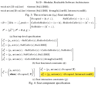
[image:5.595.246.369.113.316.2]void sit(ID caller) throws(NullIDEX);
[image:6.595.133.473.90.394.2]void arise(ID caller)throws(NullIDEX,WrongCallerEX,InteractionEX);
Fig. 3: Thesit/arise(iSA) Seat interface
<D=
ID h:=⊥
,preds=
Occupied= (h6=⊥), NullCaller(c) = (c=⊥),
CallerIsHolder(c) = (c=h),HolderIsCaller(c) = (h0=c),
NoHolder= (h0=⊥),
,
Ps={piSA
s },Pp=/0,φ,χ>
(a) Seat top-level specification "
sφ1= ps,sit(c),¬NullCaller(c),HolderIsCaller(c)
sφ2= ps,sit(c),NullCaller(c),NullIDEX
#
aφ1= ps,arise(c),¬NullCaller(c)∧CallerIsHolder(c),NoHolder aφ2= ps,arise(c),NullCaller(c),NullIDEX
aφ3= ps,arise(c),¬CallerIsHolder(c),WrongCallerEX
(b) Seat functional constraints (φ)
"
sχ1 = ps,sit(c),
when(¬Occupied),T !#
aχ1 = ps,arise(c),Occupied,T
a2χ= ps,arise(c),¬Occupied,InteractionEX
(c) Seat interaction constraints (χ) Fig. 4: Seat component specification
1.2 Paper Structure
We consider first component specifications in XCD, concentrating then on connectors – their specification in a decentralized manner that facilitates their implementation and analysis, and the fundamental properties that a connector should provide. We then con-sider role strategies for expressing control and other design decisions, and present an evaluation of the approach before discussing related work and concluding.
2
X
CD Components
Fig. 3 shows theiSAinterface implemented by Seat components; theget/putone im-plemented by Forks (iGP) is exactly the same. Methodsitthrows aNullIDEX excep-tion, whilearisealso throwsWrongCallerEXwhen the Seat is occupied by someone that is not the caller. However, arisethrows yet another exception – the enigmatic
InteractionEX. Components “throw” this special exception when theirminimal
in-teraction constraints(rather than functional ones) have been violated, to denote subse-quent chaotic behaviour. If one opens the door of a washing machine while it is washing, subsequent behaviours include everything, even electrocution.
2.1 Extending DbC – Different Contract Types
pre(sχ1)→V pre(s
φ
1)→post(s
φ
1)
pre(sφ2)→post(sφ2)
!
,pre(aχ1)→V
pre(aφ1)→post(aφ1)
pre(aφ2)→post(aφ2)
pre(aφ3)→post(aφ3)
,pre(aχ2)→post(aχ2)
Fig. 5: Constraint composition semantics
the “socket” and “plug” ports (empty set) respectively, i.e., the onesprovidingsome interface and theseusingsome interface – what in CORBA arefacetsandreceptacles. Finally, it definesfunctional(φ) andinteraction(χ) constraints, as in Fig. 4b and 4c.
All constraints use the syntax(port-expr.,method,pre-condition,post-condition). They are grouped ([]) by the(port-expr.,method)pair they apply to. They are labelled here for easy reference as(s|a)(φ|χ) – forsit/arise(s|a) and for
functional/interac-tion (φ|χ). So insφ1,ps’ssitpre-condition is ¬NullCaller(c)andHolderIsCaller(c) its post-condition, wherecissit’s parameter. This is a JML “normal behaviour”, un-likesφ2 that throws aNullIDEXif the pre-conditionNullCaller(c)is true. Constraints aφ1,aφ2 are similar ones forarise, whileaφ3 covers the case when the pre-condition is
¬CallerIsHolder(c). In that case, the post-condition throws aWrongCallerEX. This last constraintaφ3 introduces the difference between functional and (minimal) interaction constraints. Methodariseaccepts calls where the caller is not the current seat holder and throws an exception, whilesitdoes not specify anything about this. According tosφ1 it seems it simply replaces Seat’s holder with the caller. However, this is captured in Fig. 4c, through Seat’sminimal interaction constraints. Constraintsχ1asks thatsitbe delayed untilOccupiedis false. This is expressed using the “when” keyword as in JML’s extension for multi-threaded programming [33], though in XCD functional constraints are not allowed to use it. To relate it to JML, one can think of it as a “normal” interaction behaviour, describing a method’s acceptable concurrent behaviours. For all “normal” interaction constraints of components, the post-condition is alwaysT. Fig. 4c also specifies the minimal interaction constraints of arise. Constraintaχ1 states that callingariseon an occupied Seat is acceptable. Constraint a2χ, however, states that callingariseon an unoccupied Seat, results in anInteractionEXexception (which functional constraints cannot use). This is a situation that Seat does not know how to deal with, like calling a method on a component without having initialized it first. An
InteractionEXexception leads toundefined/chaoticcomponent behaviour.
Interaction constraintstake precedenceover functional ones and if both can throw an exception then the exception thrown isInteractionEX. Withpre(φ)andpost(φ) standing for the pre-condition and the post-condition respectively of a constraintφ, the real specification of the Seat constraints is shown in Fig. 5. As highlighted there for aχ2, when an interaction exception’s precondition is true, then the functional constraints are ignored. Otherwise, when the pre-condition of a normal interaction constraint is satisfied, the functional constraints should also be satisfied.
If one specified contracts in the usual JML manner, they would needF×Icases in the worst case, combiningFfunctional andIinteraction constraints, e.g., forarise: Case 1:pre(a1χ)∧pre(aφ1)→post(aφ1) Case 3:pre(aχ1)∧pre(aφ3)→post(aφ3)
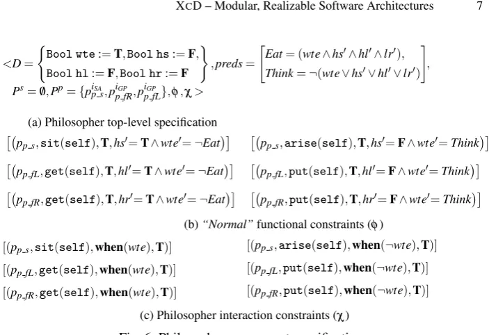
<D=
(
Bool wte:=T,Bool hs:=F,
Bool hl:=F,Bool hr:=F )
,preds=
"
Eat= (wte∧hs0∧hl0∧lr0),
Think=¬(wte∨hs0∨hl0∨lr0)
#
,
Ps=/0,Pp={piSA
p s,pip fRGP ,p iGP
p fL},φ,χ>
(a) Philosopher top-level specification
pp s,sit(self),T,hs0=T∧wte0=¬Eat
pp fL,get(self),T,hl0=T∧wte0=¬Eat
pp fR,get(self),T,hr0=T∧wte0=¬Eat
pp s,arise(self),T,hs0=F∧wte0=Think
pp fL,put(self),T,hl0=F∧wte0=Think
pp fR,put(self),T,hr0=F∧wte0=Think
(b)“Normal”functional constraints (φ)
[(pp s,sit(self),when(wte),T)]
[(pp fL,get(self),when(wte),T)]
[(pp fR,get(self),when(wte),T)]
[(pp s,arise(self),when(¬wte),T)] [(pp fL,put(self),when(¬wte),T)] [(pp fR,put(self),when(¬wte),T)]
[image:8.595.133.485.94.335.2](c) Philosopher interaction constraints (χ)
Fig. 6: Philosopher component specification
Repeating “pre(a1χ)” each time makes specifications more difficult to read than they need be and much easier to get wrong. The introduction of the (minimal) interaction constraintsimposesa much cleaner and modular manner (and guides the specification of connectors as discussed later).
2.2 Extending DbC – Service Consumer Contracts
In DbC service providers specify pre-/post-conditions for their methods but service con-sumers cannot express their own contractual clauses on them. Indeed, most languages do not allow consumers to even declare the services/interfaces they use. However, in component models like CORBA one declares both the services it provides (our sockets) and those it consumes (our plugs). Here weextend DbC further, so that we canspecify contracts for consumed servicesas well. This is done for the Philosopher in Fig. 6a. Philosopher has a Boolean variablewte(“want to eat”), and three more (hs,hl,hr) to state whether it has a Seat, a left and a right Fork respectively. These change their values according to its functional constraints in Fig. 6b,which apply when a method does not throw an exception– that is why we call them “normal”. On exceptions components do not update their data. Keywordselfdenotes theIDof the component instance.
released. These constraints were added so that the system can deadlock. Otherwise, Philosopher can always release the resources it holds when those it needs are not avail-able. It is exactly for this that we have introduced functional and interaction constraints to plug ports (required interfaces). They are needed to express the constraints under which the service providers must operate, i.e., the service’s“environment model”.
2.3 Component Structure and its Translation to FSP
XCD components have six components – Data, Predicates, Socket Ports, Plug Ports, Functional Constraints, and Interaction Constraints. We encode these into the FSP pro-cess algebra [26] by first creating a propro-cess for the Data component of each component C, that acts as the XCD component’s internal memory.
1C _ M e m = D ([ I n i t i a l V a l u e ( V )])* ,
2D ([ N a m e ( V ): T y p e ( V ) ] ) * = r e a d ([ N a m e ( V ) ] ) * - > D ([ N a m e ( V ) ] ) * 3 | w r i t e ([ N a m e ( V ) _n : T y p e ( V ) ] ) * - > D ([ N a m e ( V ) _n : T y p e ( V ) ] ) * .
That is, a state of the memory is indexed for each Data variable (V) and the initial state is selected according to the initializations in the Data component.Name/Type(V)produces the name, respectively type, of the variable and the star operator means zero or more oc-currences of its operand. Our translator currently supports Boolean and bounded integer variables. For Philosopher, this produces:
1P h i l o s o p h e r _ M e m = D [ T r u e ][ F a l s e ][ F a l s e ][ F a l s e ] , 2D [ wte : B o o l ][ hs : B o o l ][ hl : B o o l ][ hr : B o o l ]
3 = ( r e a d [ wte ][ hs ][ hl ][ hr ] - > D [ wte ][ hs ][ hl ][ hr ] 4 | w r i t e [ w t e n : B o o l ][ hsn : B o o l ][ hln : B o o l ][ hrn : B o o l ] 5 - > D [ w t e n ][ hsn ][ hln ][ hrn ] ) .
Then each port P of a component C is encoded as an FSP process that locks the memory, reads its current state, and evaluates the interaction constraints of the port’s methods.
1C_P ( ID =1) = Port ,
2P o r t = ( l o c k - > r e a d ([ N a m e ( V ): T y p e ( V ) ] ) * - > P ([ N a m e ( V )])*) , 3P ([ N a m e ( V ): T y p e ( V ) ] ) * =
4 { f o r a l l ( m : Method , i : I n t e r a c t i o n _ C o n s t r a i n t )
5 w h e n ( pre ( i n t e r a c t i o n ( m , i ))) m ([ N a m e ( arg ): T y p e ( arg ) ] ) * 6 - > i n t e r n a l _ m ([ N a m e ( arg ) ] ) * ([ N a m e ( V ) ] ) *
7 - > i n t e r n a l _ m ([ N a m e ( arg ) ] ) * ([ N a m e ( V ) _n : T y p e ( V ) ] ) *
8 [ r : RES ][ e : EX ]
9 - > ( w h e n ( N o E X C E P T I O N != e ) u n l o c k
10 - > R E S _ m ([ N a m e ( arg ) ] ) * [ r ][ e ] ([ N a m e ( V ) ] ) *
11 ([ N a m e ( V ) _n ])*
12 | w h e n ( N o E X C E P T I O N == e ) write([Name(V) n])* - > u n l o c k 13 - > R E S _ m ([ N a m e ( arg ) ] ) * [ r ][ e ] ([ N a m e ( V ) ] ) *
14 ([ N a m e ( V ) _n ])* )
15...
16 } // end of f o r a l l ( m , i )
Here, when a method m’s ithinteraction precondition is satisfied, a call to it is accepted (m([Name(arg):Type(arg)])*) and it is passed to another process through the internal m action. The other process, which can be seen as m’s “implementation”, responds by an action internal m which has the same values for the arguments and the new values for the Data variables, as well as the result (r) and exception (e) returned. When there is an exception the memory is unlocked and we pass control to sub-process “RES m”. When there is no exception we update the memory, unlock it and then pass control to RES m. Here, RES m is a sub-process of P (one per method m) responsible for checking m’s functional constraints, using m’s arguments (arg), return type (r), exception thrown (e), and values of the Data variables (V). Predicates are expanded wherever they are used.
Processes implementing a method m (those controlling the “internal m” actions), follow this pattern, where C is the component name and P its port:
1C _ P _ m ( ID =1) = (
2 i n t e r n a l _ m ([ N a m e ( arg )]: T y p e ( arg ))* ([ N a m e ( V ): T y p e ( V ) ] ) * 3 - > ({ f o r a l l ( f : F u n c t i o n a l _ C o n s t r a i n t )
4 w h e n ( pre ( f u n c t i o n a l ( m , f )))
5 i n t e r n a l _ m ([ N a m e ( arg ) ] ) * ([ V ’ ] ) * [ r ’][ e ’] - > C _ P _ m } 6 | w h e n !( CP2 ) i n c o m p l e t e _ p r e _ c o n d i t i o n s - > E R R O R ). 7// w h e r e CP2 is {∨f pre ( f u n c t i o n a l ( m , f ))} -- see eq. (2) below 2.4 Testing Architectural Components
Following Fig. 5’s constraint semantics, one needs to check that(CP1)the interaction
pre-conditions arecomplete; and thatwhenever the normal interaction pre-conditions are satisfiedthat(CP2)the functional pre-conditions arecomplete; and(CP3)the
func-tional constraints areconsistent.
CP1=∀m.
_
n pre(mχ
n) (1)
CP2=∀m.
^
k
pre(mχk)→_
n pre(mφ
n) !
(2)
CP3=∀m.
^
k
pre(mχk)→^ n
pre(mφ
n)→post(mφn)
!
(3)
In equation (1)nranges over both the normal and exceptional interaction constraints and the predicatewhen(φ)always evaluates toT. So for Seat’ssit, we need to verify thatpre(sχ1)holds. Being awhenpredicate, this is the case. For Seat’sarisewe can also verify that(pre(a1χ)∨pre(a2χ)) = (Occupied∨ ¬Occupied)holds. In equation (2) kranges over thenormalinteraction constraints of methodmandnranges over all its functional constraints. Both here and in equation (3) the predicatewhenis evaluated as theidentityfunction, i.e.,when(φ) =φ. This is because we want to evaluate the com-pleteness of the functional pre-conditions only when the method is eventually executed, in which case thewhencondition should hold.
TheCP3condition is effectively checked in our FSP models through the RES m
1R E S _ m ([ N a m e ( arg ): T y p e ( arg ) ] ) *
2 [ r : RES ][ e : EX ] ([ N a m e ( V ): T y p e ( V ) ] ) * =
3Let CP3 ={∧f ! pre ( f u n c t i o n a l ( m , f )) || p o s t ( f u n c t i o n a l ( m , f ))}
4 w h e n ( CP3 ) m _ r e t ([ N a m e ( arg ) ] ) * [ r ][ e ] - > P o r t 5| w h e n (! CP3 ) i n c o n s i s t e n t _ n o r m a l _ c o n d i t i o n s - > E R R O R
3
X
CD Connectors
We can now consider connectors, as Fork is similar to Seat. If we opt for something like procedure-call, event-bus, etc. then we are specifying our system at a very low level. The extra details obfuscate the design, making it difficult to identify the high-level interac-tion protocols, thanks to which the system achieves its non-funcinterac-tional requirements. This is why XCD focuses instead oncomplex connectors. These connectors consist of a set ofroles, each one with a set ofport variables. Role port variables are assumed by some component ports, as specified by the architectural configuration.
Glue-less Connectors XCD connectors differ from those of Wright [1], since XCD employs no “glue” element for coordinating role behaviours. The glue is problematic for a number of reasons. First, theglue is a choreography, so one needs to realize it as a set of individual services (i.e., role implementations) composed in parallel. But [2, 3] have shown that thechoreography realizationproblem isundecidablein general. De-ciding realizability in certain cases is indeed possible, e.g., [7], and in some cases unre-alizable choreographies can be repaired by extending the recipient set of messages [25]. However, this is the least of the problems introduced by glues. More importantly, if we need to consider multiple instances of some role, then we need to manually specify in the glue all the acceptable composed behaviours of these instances. For example, when considering a market system with one consumer and two merchants in [12], the glue describes all possible interactions of the three roles. Thisdoes not scale– it is imprac-tical to specify a glue with five or more merchants and quasi-impossible to do so forN merchants. Finally, the glue hinders the architectural analysis for further non-functional requirements, such as reliability, performance, real-time behaviour, etc. It introduces an artificial centralization pointin the connector, even if the protocol represented by the connector does not have such a centralization point, e.g., the procedure-call. This makes analysis more difficult, since now one has to consider the real centralization points (e.g., for reliability analysis), while ignoring the fictitious ones (the glue elements of the var-ious connectors). It also makes the modelling moredifficult to validate. For example, in [12] the authors perform a probabilistic analysis of a market system, assigning a rate R1to all transitions between the consumer role and the glue and a rateR2to all
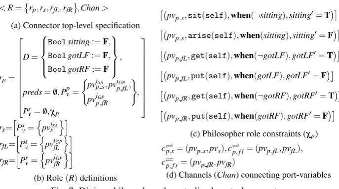
<R=
rp,rs,rfL,rfR ,Chan>
(a) Connector top-level specification
rp=
D=
Boolsitting:=F,
BoolgotLF:=F,
BoolgotRF:=F ,
preds=/0,Ppv=
( pviSA
p s,pviGP
p fL,
pviGP
p fR
)
,
Psv=/0,χp
rs=
h Psv=
n pviSA
s
oi
rfL=
h Psv=
n pviGP
fL
oi
rfR=
h Ps
v=
n pviGP
fR
oi
(b) Role(R)definitions
pvp s,sit(self),when(¬sitting),sitting0=T
pvp s,arise(self),when(sitting),sitting0=F
pvp fL,get(self),when(¬gotLF),gotLF0=T
pvp fL,put(self),when(gotLF),gotLF0=F
pvp fR,get(self),when(¬gotRF),gotRF0=T
pvp fR,put(self),when(gotRF),gotRF0=F
(c) Philosopher role constraints (χp)
cp,s= (pvp s,pvs),cp,f l= (pvp fL,pvfL),
cp,f r= (pvp fR,pvfR)
[image:12.595.136.480.114.306.2](d) Channels (Chan) connecting port-variables
Fig. 7: Dining philosophers decentralized control connector
Wrapper-like Connectors In [1], a component should implement the roles it assumes,
L(Comp)⊆L(Role), i.e., have the same set of behaviours as the role or a subset of that. This seems too constraining and limiting component reusability. Instead, XCD components focus on implementing just the minimum interaction constraints that they need to operate correctly. The roles they assume act as a sort ofwrapper, controlling their behaviour so that it meets the expected role behaviours.
Another way of looking at it is to consider components as machines that (modulo their constraints) execute the script (constraints) specified by the connector roles they assume, just like human actors do.
3.1 Decentralized Control Connector
Fig. 7 shows the specification of a complex Decentralized Control connector for the din-ing philosophers. The connector defines a set of roles and interaction channels (Fig. 7a). The specifications of the roles are shown in Fig. 7b. Each of them has five constituent parts: a set ofrole data variables(D), a set ofpredicates(preds), a set ofplug port vari-ables(Ppv), a set ofsocket port variables(Psv), and a set ofinteraction constraints(χ). Rolesrs,rfL, andrfR, have socket port variables only (rest omitted for brevity). Rolerp uses variables to keep track of the state of resources and to control it through its con-straints in Fig. 7c so that it only acquires resources when it does not hold them already and releases them when it does hold them. Constraints modify role variables only when the respective methods do not raise exceptions. Channels in Fig. 7d state which role port variables are linked to each other – all the channels we use arerendez-vousones.
3.2 FSP Encoding of XCD Connector Roles
Encoding connector role port variables is similar to encoding component ports. The only difference is that since roles do not have functional constraints, a request for a method “m([Name(arg):Type(arg)])*” is immediately followed by a response through its corresponding “m ret” action (performed by some component’s RES m sub-process).
3.3 Fundamental Connector Properties
There aretwo fundamental connector safety properties:(XP1)local deadlock-freedom;
and(XP2)interaction exception-freedom. Local deadlock-freedom(XP1)requires each
connector role to not cause its component to deadlock by constraining it too much. This can be checked at a local level by showing thatL(CompkRole)@ΣRole⊆L(Role), where @ projects a language on an alphabet.
However, interaction exception-freedom(XP2)is a connector-level property. It re-quires that component socket ports never throw an interaction exception, no matter how the component plug ports behave. This can be checked by composing the connector with the corresponding components that assume its roles,while setting all interaction pre-conditions of component plug ports toT (i.e., those in Fig. 6c). Doing so allows us to explore all possible interaction patterns that the connector roles allow for the compo-nents and verify that interaction exceptions have been rendered impossible by it.
Of course, these two safety properties do not guarantee that the connector as a whole (or for that matter the system) will be deadlock-free. Nevertheless we do not view this as being problematic because we believe that connector-level deadlock-freedom is best met through external role strategies as discussed in section 4.
4
Role Strategies – Control/Design Decisions
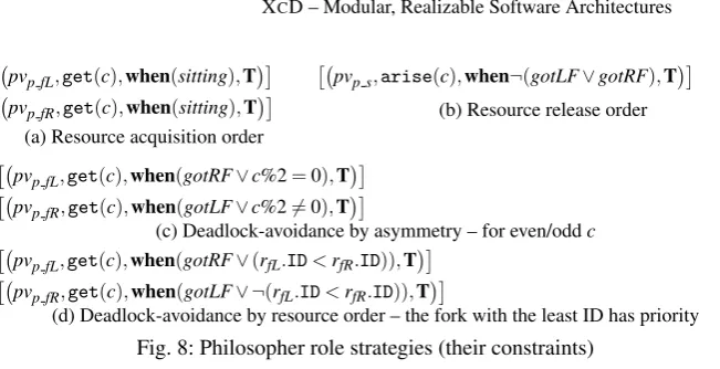
XCDadvocates the underspecification of connectors– additional interaction properties are to be imposed throughmodular role strategies[22]. These can enforce an action or-der, e.g., that Seat is acquired before the Forks, or render the system deadlock-free. Deadlock-freedom can usually be achieved through different techniques. Instead of hard-coding one in the connector, XCD allows designers to re-use the same connec-tor specification and experiment with different strategies for it in a modular fashion.
Fig. 8 shows examples of such strategies for the Philosopher role. The strategy in Fig. 8a forces Seat to be acquired before the Forks, while that of Fig. 8b forces Forks to be released first. Then the asymmetry strategy in Fig. 8c avoids deadlocks by picking a different Fork when theIDof the callercis odd or even. The strategy in Fig. 8d also avoids deadlocks but does so by always acquiring the Fork with the smallestIDfirst.
Strategies are encoded in FSP like roles are. Finally, configurations are encoded by a series of action prefixing, renaming, etc., that are too tortuous to describe in detail.
5
Evaluating X
CD’s Modular Specifications
pvp fL,get(c),when(sitting),T
pvp fR,get(c),when(sitting),T
(a) Resource acquisition order
pvp s,arise(c),when¬(gotLF∨gotRF),T (b) Resource release order
pvp fL,get(c),when(gotRF∨c%2=0),T
pvp fR,get(c),when(gotLF∨c%26=0),T
(c) Deadlock-avoidance by asymmetry – for even/oddc
pvp fL,get(c),when(gotRF∨(rfL.ID<rfR.ID)),T
pvp fR,get(c),when(gotLF∨ ¬(rfL.ID<rfR.ID)),T
(d) Deadlock-avoidance by resource order – the fork with the least ID has priority
Fig. 8: Philosopher role strategies (their constraints)
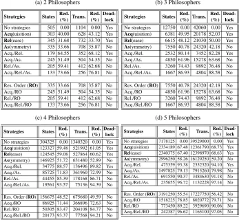
establish that our architectural specifications can be verified automatically indeed and to obtain some early results on the usefulness of modular specifications. In particular we wanted to evaluate the usefulness of control strategies and how these could aid design-ers when developing an architecture. In total, we considered 12 different configurations for the decentralized system, shown in Fig. 1 for two philosophers, using different com-binations of strategies. In all these cases our models remained the same, with the only difference being the enabling/disabling of strategies. This cannot be stressed enough – without such a modular specification it would have been extremely difficult to encode in FSP the different models of connector/strategy combinations or, even worse, the dif-ferent models of connector/strategy/component combinations if we were to use AADL-like simple connectors. Not having a compiler initially (a prototype one is available now) had forced us to increase the modularity of our language as much as possible. This modularity maximizes architectural exploration in practice – one can start with minimal component and connector specifications and test multiple strategies without having to modify any specifications.
[image:14.595.141.467.95.262.2]The different role strategies defined in Fig. 8 allow designers to easily experiment with controlling their system and evaluating different design decisions early on. XCD aids designers to decide on, andexplicitly document, the relative importance of the vari-ous system properties and the specific solutions they have provided for each. XCD also makes it easier to experiment with different strategies and configurations of strategies, as these are represented explicitly and externally to connectors.
Table 1: Different decentralized control strategy combinations (a) 2 Philosophers
Strategies States Red.
(%) Trans.
Red. (%)
Dead-lock
No strategies 505 0.00 1104 0.00 Yes
Acq(uisition) 303 40.00 628 43.12 Yes
Rel(ease) 345 31.68 732 33.70 Yes
As(ymmetry) 335 33.66 708 35.87 No
Acq./Rel. 179 64.55 352 68.12 Yes Acq./As. 245 51.49 504 54.35 No Rel./As. 205 59.41 412 62.68 No Acq./Rel./As. 133 73.66 256 76.81 No
Res. Order (RO) 335 33.66 708 35.87 No
Acq./RO 245 51.49 504 54.35 No
Rel./RO 205 59.41 412 62.68 No
Acq./Rel./RO 133 73.66 256 76.81 No
(b) 3 Philosophers
Strategies States Red.
(%) Trans.
Red. (%)
Dead-lock
No strategies 12750 0.00 42060 0.00 Yes
Acq(uisition) 6381 49.95 20178 52.03 Yes
Rel(ease) 6615 48.12 21030 50.00 Yes
As(ymmetry) 7550 40.78 24320 42.18 No
Acq./Rel. 2532 80.14 7452 82.28 Yes Acq./As. 4850 61.96 15278 63.68 No Rel./As. 3260 74.43 9892 76.48 No Acq./Rel./As. 1667 86.93 4804 88.58 No
Res. Order (RO) 7550 40.78 24320 42.18 No Acq./RO 4850 61.96 15278 63.68 No Rel./RO 3260 74.43 9892 76.48 No Acq./Rel./RO 1667 86.93 4804 88.58 No
(c) 4 Philosophers
Strategies States Red. (%) Trans.
Red. (%)
Dead-lock
No strategies 304325 0.00 1340320 0.00 Yes
Acq(uisition) 123327 59.48 521992 61.05 Yes
Rel(ease) 124545 59.08 527864 60.62 Yes
As(ymmetry) 146925 51.72 631480 52.89 No Acq./Rel. 34775 88.57 136496 89.82 Yes Acq./As. 85725 71.83 361960 72.99 No Rel./As. 44455 85.39 178168 86.71 No Acq./Rel./As. 19561 93.57 75136 94.39 No
Res. Order (RO) 156675 48.52 675680 49.59 No Acq./RO 86925 71.44 366896 72.63 No Rel./RO 50305 83.47 204108 84.77 No Acq./Rel./RO 20173 93.37 77568 94.21 No
(d) 5 Philosophers
Strategies States Red. (%) Trans.
Red. (%)
Dead-lock
No strategies 7178125 0.00 39529000 0.00 Yes
Acq(uisition) 2334189 67.48 12361790 68.73 Yes
Rel(ease) 2340375 67.40 12398970 68.63 Yes
As(ymmetry) 2996250 58.26 16129250 59.20 No Acq./Rel. 475359 93.38 2332320 94.10 Yes Acq./As. 1497825 79.13 7915260 79.98 No Rel./As. 691550 90.37 3484630 91.18 No Acq./Rel./As. 235655 96.72 1132228 97.14 No
Res. Order (RO) 3191250 55.54 17227750 56.42 No Acq./RO 1518225 78.85 8020772 79.71 No Rel./RO 773450 89.22 3929690 90.06 No Acq./Rel./RO 242387 96.62 1165100 97.05 No
strategies, if they need to use the extra degrees of freedom for meeting other critical properties, e.g., performance. This is made possible by the modular nature of the strate-gies – adding and removing them requires no modifications to either component or connector specifications.
A connector for centralized control (with a “Butler” role) and associated evaluation results is described in a separate technical report [23].
6
Related Work
Research in software architectures identified the need for first-class connectors from the very beginning [15, 30]. The problems created by the non-documentation of protocols was also identified early on in [14] and a formalization of connectors was presented in [1] shortly after that – a formalization that is still being used today, e.g., [19,34]. Indeed, the connectors in CONNECT [19] follow the same general structure as Wright’s (roles and glue), but seem to be specified in FSP instead of CSP. Compared to Wright [1], XCD adds the extra element ofrole strategy, and the additional constraint that connec-tors and strategies shouldnot have a glue. As such XCD avoids the glue realizability problem – XCD connector roles are realizable by construction, as they only require ac-cess to local data (Booleans, integers, buffers, etc.). XCD also abandons the use of CSP for what we believe is a more developer-friendly approach.
Work which has been done at identifying different types of connectors [16, 27] has tended to focus at cataloguing and specifying basic interaction mechanisms, e.g., proce-dure calls, event buses, etc., especially since these were needed to base upon them more complex connectors. However, the use of basic interaction mechanisms as connectors in an architectural specification makes it difficult to understand what the real protocols in the system are and leads to system specifications that are at a very low level of ab-straction, as is the case with AADL [11]. Indeed, designers are forced to incorporate the behaviour of the more complex connectors they wish to use into their components, de-creasing their re-use potential and inde-creasing the chance of architectural mismatch [14]. In fact, the presence of low-level connectors [16, 27] in a system architecture should alert designers that they have a potential problem. That is, they haveover-designedthe architectural description and/or have failed to describe the general protocols that are supposed to be used among their components in a way that is sufficiently abstract, and therefore understandable and analyzable. Blackboards, event buses, tuple spaces, etc., are low-level interconnection mechanisms that give precious little information on what interaction protocols a system uses and how these meet its non-functional requirements. Languages used by practitioners suffer from this problem in particular. A connec-tor in UML 2.0 is just a UML association, so architects must use modelling elements other than UML connectors to describe architectural connectors [20]. AADL [13] only supports certain specific, basic connector types and does not offer the possibility to de-fine more complex connector types, while SysML [6] does not support architectural connectors at all (only UML ones).
the component. Instead, XCD cleanly separates component and connector behaviour, and further separates the control parts of the connectors through role strategies.
It should be noted here that the constraints introduced through strategies are orthog-onal to architectural style constraints, such as those of ACME [21]. The latter are global constraints enforcing a style, while strategies are local constraints. So there are cases where the strategy constraints are met but the style ones are not, as in a pipe-and-filter style prohibiting cycles, something that cannot be enforced through role strategies.
Compared to BIP [8], XCD differs in the fact that it tries to support complex connec-tors as first class entities, while BIP only provides two basic connecconnec-tors, for “rendez-vous” and “atomic broadcast”. We believe that latter can be misused very easily by designers who mistake it for “broadcast”. At the same time, BIP offers a specification framework that is closer to synchronous/hardware description languages that XCD tries to avoid as we believe that languages like JML will prove much more popular with soft-ware developers.
Compared to Exogenous Connectors [24] and Reo [4], XCD differs by introduc-ing role strategies and by not tryintroduc-ing to remove interaction constraints from components entirely. We believe that components still need to be able to specify some interaction constraints so as to describe what they expect of their environment and how they plan to use it. Another difference is with the way a designer is expected to specify their system. XCD uses pre-/post-conditions to specify the behaviour of components, connectors, and strategies, while exogenous connectors uses a graphical representation, which to our eyes looks too much like hardware block diagrams. Reo also constructs complex connectors by the appropriate composition of simpler channel specifications, in a man-ner that again resembles a circuit design. We do not expect such languages to gain a significant follow up from the general software development community – they do not look like “code” enough.
7
Conclusions
service “environment model”. Finally, by foregoing the use of Wright’s [1] connector glue element and instead expressing all constraints through local pre-/post-conditions, XCD ensures thatconnectors can be realized by constructionand thatconnectors can be easily specified even in the case where the number of roles is high (or a parameter). Apart from improving tool support, we are currently considering extensions of XCD so that it can deal with events (i.e., asynchronous oneway calls), and different types of interaction channels (buffered, lossy, etc.).
Acknowledgements This work has been partially supported by the EU project FP7-257367 IoT@Work – “Internet of Things at Work”.
References
1. Allen, R., Garlan, D.: A formal basis for architectural connection. ACM TOSEM 6(3), 213– 249 (Jul 1997)
2. Alur, R., Etessami, K., Yannakakis, M.: Inference of message sequence charts. IEEE Trans. Software Eng. 29(7), 623–633 (2003)
3. Alur, R., Etessami, K., Yannakakis, M.: Realizability and verification of MSC graphs. Theor. Comput. Sci. 331(1), 97–114 (2005)
4. Arbab, F.: Reo: A channel-based coordination model for component composition. Mathe-matical Structures in Computer Science 14(3), 329–366 (2004)
5. B´alek, D., Plasil, F.: Software connectors and their role in component deployment. IFIP Conf. Proc., vol. 198, pp. 69–84. Kluwer (2001)
6. Balmelli, L.: An overview of the systems modeling language for products and systems de-velopment. J. of Obj. Tech. 6(6), 149–177 (Jul–Aug 2007),www.sysml.org
7. Basu, S., Bultan, T., Ouederni, M.: Deciding choreography realizability. In: Field, J., Hicks, M. (eds.) POPL’12. pp. 191–202. ACM (2012)
8. Bliudze, S., Sifakis, J.: The algebra of connectors – Structuring interaction in BIP. In: Em-Soft. pp. 11–20 (Oct 2007)
9. Chalin, P., Kiniry, J.R., Leavens, G.T., Poll, E.: Beyond assertions: Advanced specification and verification with JML and ESC/Java2. In: FMCO’05 – Formal Methods for Comp. and Obj. LNCS, vol. 4111, pp. 342–363. Springer (2006)
10. Dehnert, J.C., Stepanov, A.A.: Fundamentals of generic programming. In: Jazayeri, M., Loos, R., Musser, D.R. (eds.) Generic Programming. Lecture Notes in Computer Science, vol. 1766, pp. 1–11. Springer (1998)
11. Delanote, D., Van Baelen, S., Joosen, W., Berbers, Y.: Using AADL to model a protocol stack. In: ICECCS. pp. 277–281 (Apr 2008)
12. Di Giandomenico, F., Kwiatkowska, M.Z., Martinucci, M., Masci, P., Qu, H.: Dependability analysis and verification for connected systems. LNCS, vol. 6416, pp. 263–277 (2010) 13. Feiler, P.H., Lewis, B.A., Vestal, S.: The SAE architecture analysis & design language. In:
IEEE Intl Symp. on Intell. Control. pp. 1206–1211 (Oct 2006),www.aadl.info
14. Garlan, D., Allen, R., Ockerbloom, J.: Architectural mismatch or why it’s hard to build sys-tems out of existing parts. In: ICSE. pp. 179–185 (Apr 1995)
15. Garlan, D., Shaw, M.: An introduction to software architecture. In: Adv. in SW Eng. and Knowledge Eng. pp. 1–39. World Scientific Publishing Company, Singapore (1993) 16. Hirsch, D., Uchitel, S., Yankelevich, D.: Towards a periodic table of connectors. In:
17. Hoare, C.A.R.: An axiomatic basis for computer programming. Commun. ACM 12(10), 576–580 (1969)
18. Hoare, C.A.R.: Communicating sequential processes. Commun. ACM 21(8), 666–677 (1978)
19. Issarny, V., Bennaceur, A., Bromberg, Y.D.: Middleware-layer connector synthesis: Beyond state of the art in middleware interoperability. LNCS, vol. 6659, pp. 217–255 (2011) 20. Ivers, J., Clements, P., Garlan, D., Nord, R., Schmerl, B., Silva, J.R.O.: Documenting
com-ponent and connector views with UML 2.0. TR CMU/SEI-2004-TR-008 (2004)
21. Kim, J.S., Garlan, D.: Analyzing architectural styles with Alloy. In: ROSATEA (Jul 2006) 22. Kloukinas, C.: Better abstractions for reusable components & architectures. In: ICSE-NIER
– ICSE Companion. pp. 199–202. IEEE Press, Vancouver, Canada (May 2009)
23. Kloukinas, C., Ozkaya, M.: Xcd – Simple, modular, formal software architectures. Tech. Rep. TR/2012/DOC/01, Department of Computing, School of Informatics, City University London, Northampton Square, London, EC1V 0HB, U.K. (May 2012), ISSN 1364–4009. 24. Lau, K.K., Elizondo, P.V., Wang, Z.: Exogenous connectors for software components. In:
CBSE. LNCS, vol. 3489, pp. 90–106. Springer (2005)
25. Lekeas, G., Kloukinas, C., Stathis, K.: Producing enactable protocols in artificial agent soci-eties. In: Kinny, D., jen Hsu, J.Y., Governatori, G., Ghose, A.K. (eds.) PRIMA’11. Lecture Notes in Computer Science, vol. 7047, pp. 311–322. Springer (2011)
26. Magee, J., Kramer, J.: Concurrency – state models and Java programs. Wiley, 2 edn. (2006) 27. Mehta, N.R., Medvidovic, N., Phadke, S.: Towards a taxonomy of SW connectors. In: ICSE.
pp. 178–187 (2000)
28. Meyer, B.: Applying “Design by Contract”. IEEE Computer 25(10), 40–51 (1992)
29. Musser, D.R., Stepanov, A.A.: Generic programming. In: Gianni, P.M. (ed.) ISSAC’88. Lec-ture Notes in Computer Science, vol. 358, pp. 13–25. Springer (1988)
30. Perry, D.E., Wolf, A.L.: Foundations for the study of software architecture. SIGSOFT Softw. Eng. Notes 17(4), 40–52 (Oct 1992)
31. Plasil, F., Besta, M., Visnovsky, S.: Bounding component behavior via protocols. In: TOOLS (30). pp. 387–398. IEEE (1999)
32. Plasil, F., Visnovsky, S.: Behavior protocols for software components. IEEE Trans. Software Eng. 28(11), 1056–1076 (2002)
33. Rodr´ıguez, E., Dwyer, M.B., Flanagan, C., Hatcliff, J., Leavens, G.T., Robby: Extending JML for modular specification and verification of multi-threaded programs. In: ECOOP. LNCS, vol. 3586, pp. 551–576. Springer (2005)
34. Taylor, R.N., Medvidovic, N., Dashofy, E.M.: Software Architecture: Foundations, Theory, and Practice. John Wiley & Sons (2010), ISBN-13: 978-0470167748