1
Grain refinement in technically pure aluminium plates using incremental ECAP processing
W. Chrominski*1, L. Olejnik2, A. Rosochowski3, M. Lewandowska1
1
Faculty of Materials Science and Engineering, Warsaw University of Technology, Woloska 141, 02-507 Warsaw, Poland
2
Institute of Manufacturing Processes, Warsaw University of Technology, Narbutta 85, 02-524 Warsaw, Poland
3
Design, Manufacture and Engineering Management, University of Strathclyde, 75 Montrose Street, Glasgow G1 1XJ, United Kingdom
Corresponding author Witold Chrominski
Warsaw University of Technology, Faculty of Materials Science and Engineering Woloska 141, 02-507 Warsaw, Poland
e-mail: [email protected]
tel. +48-22-234-8441, fax. +48-22-234-8415
Abstract
2
associated with two different tools acting asynchronously. Eight passes were applied to technically pure aluminium, with the sample rotation by 90o around Z axis, which resulted in two full rotations and accumulated strain equal to 9.2. It was demonstrated that grain refinement under these conditions occurs very efficiently. Eight passes resulted in grain size reduction to below 500 nm and very high fraction of high angle grain boundaries of about 80%. This was attributed to the activation of different slip systems in consecutive passes (thanks to sample rotation) and the lack of redundant strain which results in early establishment of equiaxial grain structure. These two features confirm incremental ECAP to be one of the most effective severe plastic deformation methods in terms of grain size refinement and high angle grain boundaries formation.
Keywords: aluminium, equal channel angular pressing, grain refinement, electron backscattered diffraction, transmission electron microscopy
1. Introduction
Equal channel angular pressing (ECAP) is a well-established process that allows accumulating very high strains (difficult to obtain by any other conventional
deformation technique) due to no significant changes in the workpiece`s dimensions. It was originally proposed by Segal [1] and then developed by Valiev [2] and other groups around the world [3-7]. Over the last 20 years a tremendous progress has been made in tool design and fundamental understanding of the phenomena taking place during ECAP processing. Its comprehensive review can be found in [8]. Currently, ECAP is one of the most popular severe plastic deformation (SPD) methods utilized for grain refinement and obtaining so-called ultrafine grained (UFG) materials, which feature extraordinary mechanical properties due to the grain boundary strengthening
3
Microstructure evolution in consecutive ECAP passes is well described, in particular for simple materials such as pure aluminium. First stage of ECAP leads to the formation of elongated deformation bands which at finer scale are divided by
dislocation cell structure [4, 10-12]. Depending on the initial microstructure and grain size, some high angle grain boundaries (HAGBs) are already present but due to cellular structure within deformation bands, low angle grain boundaries (LAGBs) dominate in the misorientation angle distribution [4, 12]. By fourth pass (ε~ 4) dislocation cells reach their finest size (below 1µm for pure aluminium depending on deformation route) and further deformation induces mostly an increase in misorientation angles of grain and subgrain boundaries [5, 13]. Such a mechanism of microstructure evolution is basically similar to the one reported for cold rolling [14-18]. Beyond strain level of 4, further grain refinement is still possible but it occurs very slowly until it approaches saturation. Also, a fraction of HAGBs tends to reach the highest level of 70% [10].
4
occurs with no rotations of the billet (so called route A) due to the lack of redundant strain, which promotes formation of new subgrains and further effective increase of misorientation angle as deformation continues [11]. However, for any processing route, saturation in grain size and HAGB content is observed. Even at ultra high strains (ε> 10) pure aluminium processed by ECAP contains not fully refined regions with LAGB network [10-12].
Saturation in grain size refinement has been recently attributed to a common deformation direction for typical elongated rod samples [10-12]. EBSD study
demonstrated that each pass causes progressive grain elongation towards deformation direction. When lamellar grains are well developed, grain refinement can occur only by generation of transverse boundaries in favorably oriented grains [10]. This phenomenon is rather rare since all passes feature a common deformation direction, which explains low rate of grain refinement after a certain level of strain. Therefore, for further grain refinement to occur, there is a need for changing deformation direction, which can only be possible if the shape of a sample is changed, e.g. into rectangular.
One of the major advantages of ECAP processing is the possibility of producing materials that are capable of superplastic elongation at strain rates approximately two orders of magnitude faster than those currently employed for commercial superplastic forming operations, which was proven for a number of materials [7, 23-25]. However, superplastic forming operations require the material in the form of thin sheets.
5
obtain fully homogenous material. It was also used to investigate formation of texture in ECAP [29].
In this work, we propose a new approach to produce ultrafine grained plates using a modified ECAP method, namely incremental ECAP (described in details in the next paragraph). Incremental processing reduces forces and allows processing relatively large billets. In addition, the specimens are in the form of plates with rectangular shape, which makes them suitable for further processing, e.g. via deep drawing, which may extend the range of potential applications of UFG materials. They can also be rotated about Z axis (normal to the plate), which eliminates one of the factors limiting grain refinement, i.e. the same deformation direction. The specific aim of this work was to show the feasibility of processing plates by incremental ECAP and determine its efficiency in terms of grain size refinement and HAGB formation.
2. Experimental section 2.1 Incremental ECAP
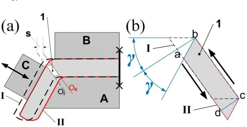
Incremental ECAP, coded here I-ECAP, is a member of big family of incremental bulk metal forming processes [30]. I-ECAP technique described for the first time in [31] uses three simple tools, Fig. 1 (a). Tools A and B define the input channel while A and C define the output channel. Tool C is a working punch, which moves in a reciprocating manner at an appropriate angle to the billet. The movement of the punch is
6
The geometrical analysis of the material flow between lines OI and OII leads to the conclusion that the mode of deformation is that of simple shear. To illustrate this point, deformation of a small element pointed with number 1 in Fig. 1 (a) is split into two steps as shown in Fig. 1 (b). Shearing the initial parallelepiped I (showed with dashed line) by angle γ produces a rectangle abcd, for which the shear strain is tgγ and the equivalent von Mises strain is ε=tgγ/√3. Continuing this shearing by another angle γ
[image:6.595.87.504.253.468.2]converts the rectangle to the final parallelepiped II and doubles the equivalent strain to ε=2tgγ/√3.
Fig. 1 Schematics of incremental shear in I-ECAP where 1 indicates material element deformed by shearing (a) tool – billet arrangement (b) deformation of basic volume element
Fig. 2 shows tool configuration used in this experiment for which γ=45°. The total equivalent strain in one cycle is ε=1.15, which is the value known from the conventional ECAP with the channel angle of 90°. Thus, in terms of the deformation
7
to be reduced compared to conventional ECAP because only a small volume of material placed in the zone between lines OI and OII, Fig 1 (a) is deformed in one cycle.
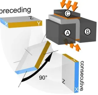
Deformation was carried out with the pusher stroke of s=0.6 mm, which is sufficient to overlap the plastic deformation zones in subsequent cycles .Also, accordingly to conventional ECAP, the sample planes were denoted as X (perpendicular to deformation), Y (lateral plane) and Z (normal to X and Y), as illustrated in Fig. 2.
First applications of I-ECAP for processing of plates have been described in Ref. [32, 33]. Deformation was performed on hydraulic presses with manual feeding of plate. Recently [34], the process has been automated using a dedicated machine with
[image:7.595.107.267.358.512.2]programmable logic controller. This enables full control of tool motion, which provides more freedom in terms of strain control.
Fig. 2 Tools configuration and schematic of applied deformation route
2.2 Material and experimental methods
Technically pure Al (99.5 weight %) was used to reveal mechanism and efficiency of grain refinement when a new I-ECAP method is applied. The material was supplied in the form of a cold rolled sheet with 3 mm thickness. Samples for the first pass of I-ECAP were square in shape (62×62 mm) with the first pass direction parallel to the
8
odd pass was in accordance with RD and the even pass was perpendicular to RD. Punch motion was adjusted to avoid changing plate thickness.
Microstructure evolution was investigated by EBSD and TEM techniques. Samples from X, Y and Z planes were thin discs first cut by a spark erosion machine and then by a wire saw. Disks for EBSD were electrochemically polished and
additionally ion polished.TEM thin foils were prepared by electropolishing to obtain electron transparent regions near the center of the foil. In both cases, the solution containing 80% methanol and 20% perchloric acid was used. The images are described in the following way - number of pass and plane of observation, for example, 1X, 3Y. Since planes X and Y change in every consecutive pass, the description always refers to the last pass of I-ECAP.
EBSD orientation mapping was performed on Hitachi SU70 analytical scanning electron microscope (acceleration voltage of 20kV) equipped with Schottky emitter. Maps were prepared using a square grid with step size of 80 nm for detailed
microstructure characterization. Each map was taken from area of about 1000 µm2; the most representative regions were chosen to be presented in this paper. To free
orientation maps from “misorientation noise”, minimal grain boundary misorientation angle was set at 10°,which resulted in clear images of deformation structures. In the analysis, HAGBs were defined as boundaries with misorientation angle of at least 15°. An ultrafine grain was defined to be smaller than 1 µm in diameter and surrounded by
HAGBs only. When some part of grain has got misorientation angle with its neighbor within the low angle regime, it was considered as subgrain.
9
Grain size was determined from EBSD maps using equivalent diameter (d2), defined as a diameter of circle with the same area as the measured grain. The grain size variation was quantified by the coefficient of variation (CV) defined as ratio of standard deviation and mean value. The measurements included both grains and subgrains. Grain elongation was evaluated by shape factor α defined as a ratio of the maximum diameter to equivalent one. TEM images were used for this purpose only for the last stage of I-ECAP for comparative analysis since this method is mostly used in literature.
Microhardness test was performed with standard Vickers indenter under a load of 200g. Low load value was chosen for higher sensibility on microstructure
heterogeneities. The tests were performed on samples with a smooth surface prepared by grinding and mechanical polishing. On each sample 20 measurements were done from which a mean values was calculated.
3. Results 3.1 EBSD
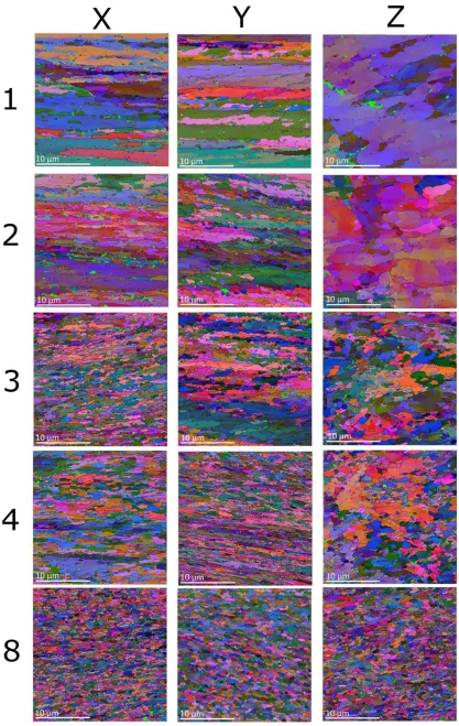
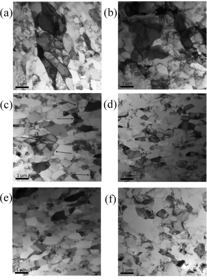
Fig.3 shows a set of EBSD orientation maps observed on X, Y and Z planes after 1, 2, 3, 4 and 8 I-ECAP passes. First pass brings about the microstructure similar to the one obtained via conventional ECAP, i.e. HAGBs separate regions with LAGB network. The microstructure is of lamellar type with HAGBs parallel to deformation direction, which can be easily noticed on 1Y plane. Additionally, the network of LAGBs is arranged in deformation bands whose tilt angle is in agreement with punch motion. The differences between microstructures observed on 1X and 1Y planes should be
underlined here as they influence further microstructural transformations. The most striking feature of 1Y plane is a very low content of transverse grain boundaries while such boundaries are quite frequent in 1X plane.
10
ultrafine grains. The results summarized in Table 1 reveal that the fraction of ultrafine grains after second pass increases to about 10% when measured on 2X and 2Y planes. It should be noted that their content was negligible after first pass. After second pass, the microstructures observed on X and Y planes are very similar with significant grain elongation along Y and X axis, respectively. The 2Z plane shows a unique
11
12
Table 1 - Fraction of ultrafine grains measured on planes X, Y and Z after different number of passes
1 2 3 4 8
X 0.03 0.08 0.25 0.34 0.77
Y 0.03 0.11 0.13 0.33 0.72
Z 0.01 0.03 0.12 0.20 0.54
Third and fourth passes result in more homogenous microstructure and increased fraction of UFGs relatively to previous passes (see Table 1). Despite the fact that grain refinement is very advanced after fourth pass, there are still some regions that are not refined. In addition, elongation of grains in the horizontal direction is still visible on both 4X and 4Y planes. This is related to rotation about Z axis since each of side planes has been Y plane, which contains deformation direction, twice.
[image:12.595.92.513.355.671.2]13
Final, eighth pass, brings about a fully refined microstructure with UFG fraction at the level of about 75% measured on 8X and 8Y planes. It should also be noted that the grains are not elongated, which means that fully homogenous equiaxial
microstructure has been obtained.
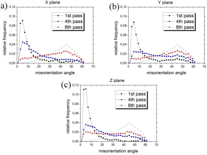
Misorientation angle distributions presented in Fig.4 show a typical shift of peak from low angle region to higher misorientation angle with increasing number of passes. However, the maximum is not so clearly distinguishable for 8Z plane, where
misorientation distribution seems to be similar for all angles. For X and Y planes, results after eighth pass are close to the Mackenzie plot [35] for random distribution, which is presented as a grey dashed line on every graph.
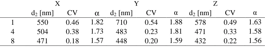
Table 2 provides results of grain/subgrain size measurements (from EBSD) on all three planes after 1, 4 and 8 passes. One can notice that the measured values depend on plane but results from X and Y planes are very close to each other from fourth pass. Generally grain size as well as CV are reduced with the increasing number of passes. This means that grain size diversity becomes narrower and microstructure become more homogenous with subsequent I-ECAP passes. The obtained result of about 500 nm is significantly smaller than 600 nm typically reported for aluminium with similar purity or 1000 nm for high purity aluminum. Shape factor α also decreases with deformation as illustrated by data for X and Y planes. This suggests that shortening of lamellas established in early passes of I-ECAP is an efficient mechanism of grain refinement. For Z plane, changes in α are only slight since this plane, as mentioned previously, undergoes deformation in mutually orthogonal directions in subsequent passes. Comparison to already published results is given in section 4.3
14
X Y Z
d2 [nm] CV α d2 [nm] CV α d2 [nm] CV α
1 550 0.46 1.82 710 0.54 1.88 578 0.49 1.63
4 504 0.38 1.73 483 0.23 1.81 471 0.33 1.58
8 471 0.18 1.57 448 0.20 1.59 432 0.22 1.56
[image:14.595.88.514.45.121.2]3.2 TEM
Fig. 5 represents a set of selected TEM micrographs taken from different planes and after different number of passes to show the most characteristic features at a finer scale. As mentioned previously, first pass of I-ECAP results in a microstructure typical for a conventional ECAP process. The microstructure consists of deformation bands with cellular structure, Fig. 5 (a). Only very few dislocations which are not involved in walls can be noticed. Contrast between neighboring bands is strong, which suggests different orientations, however, from tilting experiment in TEM it is known that they exhibit similar dislocation substructure.
Fig. 5 (b) illustrates a typical microstructure visible in Z plane after 2 passes and provides more detailed insight into the effect of rotation about Z axis previously
underlined in EBSD orientation maps. In conventional ECAP, elongation of grains is expected on this plane, which is even enhanced by subsequent passes. In the
15
Fig. 5 Selected TEM images presenting characteristic features of deformation structures in I-ECAP with rotation about Z axis: (a) 1Y (b) 2Z (c) 4Y (arrows indicate selected
transverse LAGBs) (d) 8X (e) 8Y (f) 8Z
Another unusual feature can be seen in Fig. 5 (c) which illustrates the
16
angle boundaries (indicated by arrows) that split them into grains with more equiaxial shape. They were noticed very frequently despite some of them being out of contrast on the presented image. The formation of transverse boundaries is rather rare in
conventional ECAP deformation structures. This causes significant morphological texture visible as grain elongation, which is frequently reported in literature [4, 10, 36-38]. The lack of lamellar structure breakup was reported to be the main reason for slower grain subdivision rate when such a structure is well established after four passes [11, 38, 39]. Hence, the formation of transverse boundaries is desirable in terms of grain refinement which should lead to more equiaxial structure.
Fig. 5 (d), (e) and (f) represent typical images after the eighth pass taken from X, Y and Z planes, respectively. TEM and EBSD results are fully consistent. The final microstructure is homogenous, the grains are equiaxial in shape and small in size. Subdivision of lamellas into smaller parts, mentioned in the previous section, is confirmed here by TEM imaging to be a major grain refinement mechanism for the higher number of passes. The 4Y microstructure in Fig. 3 and Fig. 5 (c) depicts numerous transverse LAGBs which transform into HAGBs via grain rotation
mechanism as can be seen in the 8Z microstructure. All images after eight passes give a general view of grains as round objects with little flattering in direction normal to Z plane. This result, accompanied by EBSD orientation mapping, suggests homogeneity of structure in the whole plate processed by I-ECAP.
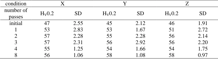
3.3 Microhardness
17
[image:17.595.81.513.208.325.2]the diversity of microhardness measurements expressed here as standard deviation decreases with increasing number of passes which can be attributed to microstructure homogenization in consecutive I-ECAP passes, as shown in the previous section.
Table 3 - Microhardness values measured on different planes of plates produced by I-ECAP, SD – standard deviation
condition X Y Z
number of
passes HV0.2 SD HV0.2 SD HV0.2 SD
initial 47 2.55 45 2.12 46 1.91
1 53 2.83 53 1.67 51 2.72
2 57 2.28 55 2.28 56 2.14
3 57 2.31 56 2.92 56 2.20
4 55 1.25 54 1.66 54 1.75
8 56 1.06 58 1.08 58 0.97
4. Discussion
4.1 Mechanism of grain refinement in I-ECAP with rotation about Z axis
It has been shown for conventional deformation processing, e.g. rolling, that early stages of deformation bring about the development of ordinary cellular structure within deformation microbands [14, 15]. For higher strain applied, a breakup of grain structure into subgrains that separates volumes with different sets of active slip systems is
observed [15]. Similar microstructure evolution takes place during first stage of ECAP as described in [5, 10-12, 39, 40]. Also, the first pass of I-ECAP leads to a similar microstructure with elongated subgrain areas separated by HAGBs.
18
clearly seen on Z plane after second pass as noticeable elongation in two orthogonal directions (see Fig. 3 and Fig. 5 (b)). The rotation about Z axis also implies a new shearing plane and the activation of different dislocation slip systems than in the
previous pass. In Fig. 5 (b), one can see dislocation structures within already established cells, which confirms this statement. Similar observations were done on every plane. On a more global scale, rotation about Z axis can promote subgrain rotation within
previously formed lamellas; as a result the fraction of UFGs increases to about 10% (Table 1). This is the outcome of subdivision of coarse grains into smaller parts and increase of misorientation angles since UFGs are defined as fully separated by HAGBs. Hence, the main refinement mechanism in this case is grain subdivision into smaller parts and their rotation. It is similar to the mechanism proposed by Sun et al. [36].
Subsequent passes enhance these phenomena. After four passes, the microstructure becomes reasonably equiaxed but still LAGBs dominate in
misorientation angle distribution (Fig. 4). However, every 90° rotation about Z axis activates different slip systems and as a result new dislocation walls can be established within the existing structure. It is the most likely explanation of the formation of transverse LAGBs inside lamellar grains as can be seen on orientation maps and more clearly on TEM 4Y micrographs in Fig. 5 (c). Here, elongated grains with parallel HABGs aligned with deformation direction are accompanied by a set of dislocation walls that shorten the lamellas and are precursors of new grain boundaries.
Second full rotation about Z axis (8 passes) causes further increase in misorientation angles, whose distribution becomes similar to that of fully random structure (is close to the Mackenzie plot). As a consequence, fraction of UFGs increases to about 75%. Hence, deformation during passes from 5th to 8th results in the
19
Table 2). Hence, first four passes have been very efficient in establishing a network of longitudinal HAGBs parallel to Z plane and transverse LAGBs perpendicular to them. Next four passes result in the formation of stable UFG structure by subdivision of lamellas via grain rotations with only slight decrease in grain/subgrain size. The final microstructure can be described as homogenous with grains close to equiaxial in shape as indicated by decreasing shape factor α in Table 2. Such a homogenous
microstructure is also reflected in microhardness results (Table 3) that show high uniformity on all X, Y and Z planes (low value of SD).
4.2 Effect of deformation route on grain refinement
In ECAP process, different stress conditions can be generated by billet rotations in consecutive passes. Such rotations have an impact on the microstructure formed [11, 36] due to differences in the orientation of shearing plane in subsequent passes. It has been shown previously that the most efficient route is A (no rotations of billet) [11] because of lack of redundant strain which can appear when deformation with cyclical rotations is applied. However, a proportional strain path does not lead to homogenous microstructure since grain subdivision into smaller parts strongly depends on the orientation, which influences active slip systems. Hence, in large grains with stable orientation, dislocation cell structure will not form easily as in grains which are not in preferable orientation and are susceptible to changing it to a more stable one via subdivision into smaller parts. This is confirmed by microstructure investigations that clearly show long fibrous grains surrounded by refined ones [4, 11],even if very large strains were applied.
20
attributed to redundant shear strain which has been proved to be undesirable in terms of grain refinement [11, 22]. In every even pass, some part of dislocations has been
reverted by 180° rotation.
This can be partially overcome by introducing more shear planes by 90°
rotations between consecutive passes (route BC). In the second pass of route BC, part of the dislocation structure generated in the first pass remains stable because of the
activation of slip systems that were not available previously. Dislocations created in this way stabilize already present structures and the effect of redundant shear strain is not as effective as in the case of second C pass. Hence, the grain refinement via route BC occurs more quickly and established microstructure is more equiaxial but
misorientations angle spread is much narrower than in route A without redundant strain. This approach strongly implies that lack of redundant strain, which is achieved in route A and activation of different slip systems in route BC, are the two main features that are most beneficial in the grain refinement process. The new route with rotations about Z axis, proposed in this study, combines the advantages of route A and route BC, allowing these two desired phenomena to work mutually. The orientation of work piece planes does not change in terms of their orientation relatively to the tools. It means that punch always presses the same plane. Hence, there is no stress reversion. According to literature this strongly influences the formation of new HAGBs [11, 22], which can be noticed on misorientation angle distribution which is close to random distribution, as illustrated in Fig. 4.
21
be used together in conventional ECAP, seem to work efficiently and result in a
reasonably uniform microstructure with high fraction of UFGs and misorientation angle distribution close to random.
4.3. Comparison of I-ECAP to ECAP
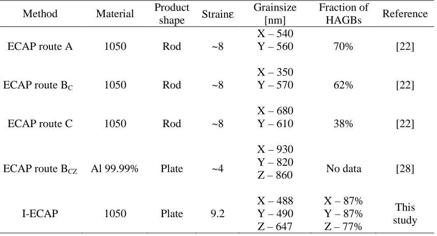
Table 3 gathers ECAP parameters that are frequently used for comparative purposes in the literature. The results presented in Table 3 were obtained for the same alloy and similar accumulated strain as used in this study with one exception of route BCZ. One can see the influence of deformation route on microstructure expressed with physical quantities. Typical grain size after ECAP is about 600 nm while the fraction of HAGBs ranges from 38%to 70%. ECAP of plates was performed for high purity aluminium, which is more susceptible to dynamic recovery as reported in [38]. Additionally lower accumulative strain was applied, probably because of technical difficulties related to billet's shape. This resulted in grain size of about 900 nm.
This comparison clearly shows that I-ECAP of plates with rotation about Z axis is very efficient in terms of microstructure refinement as the grain size is the smallest reported (below 500 nm) and fraction of HAGBs is around 80% for all investigated planes. This makes the I-ECAP technique very promising in terms of obtaining flat products
22
Table 4 - Comparison of I-ECAP with other techniques; grain size measured by TEM
Method Material Product
shape Strainε
Grainsize [nm]
Fraction of
HAGBs Reference
ECAP route A 1050 Rod ~8
X – 540
Y – 560 70% [22]
ECAP route BC 1050 Rod ~8
X – 350
Y – 570 62% [22]
ECAP route C 1050 Rod ~8
X – 680
Y – 610 38% [22]
ECAP route BCZ Al 99.99% Plate ~4
X – 930 Y – 820
Z – 860 No data [28]
I-ECAP 1050 Plate 9.2
X – 488 Y – 490 Z – 647
X – 87% Y – 87% Z – 77%
This study
5. Conclusions
1. I-ECAP of rectangular plates was successfully applied with two full rotations about Z axis (eight passes), which kept the same side of the plate interacting with punch.
2. Rotations about Z axis promote activation of different slip systems in
consecutive passes that leads to intersections of dislocations in early stages (pass 1-4) of I-ECAP. Lack of redundant strain results in early establishment of
equiaxial grain structure. Further passes lead to slower rate of grain refinement and steady evolution of high angle grain boundaries.
23 Acknowledgements
This work was carried out within a NANOMET Project financed under the European Regional Development Fund (contract no. POIG.01.03.01-00-015/08).
References
[1] V.M. Segal, V.I. Reznikov, A.E.Drobyshevsky, V.I.Kopylov. Russ Metal 1981; 1: 99-105
[2] R.Z.Valiev, N.A. Krasilnikov, N.K. Tsenev, Mater SciEng A 1991: 137: 35-40 [3] P.W.J. Mckenzie, R. Lapovok, Y. Estrin. Acta Mater 2007; 55: 2985-93 [4] Y. Iwahashi, Z. Horita, T.G. Langdon. Acta Mater 1998; 46: 3317-31
[5] M. Cabibbo, W. Blum, E. Evangelista, M.E. Kasser, M.A. Meyers. Metall Mater Trans A; 2008: 181-89
[6] P.L. Sun, P.W. Kao, C.P. Chang. Mater SciEng A 2000; 283: 82-85 [7] R.B. Figueiredo, P.R. Cetlin, T.G. Langdon. Acta Mater 2007, 55. 4769-79 [8] R.Z. Valiev, T.G. Langdon. Prog Mater Sci 2006; 51: 881-981
[9] M.A. Meyers, A. Mishra, D.J. Benson. Prog Mater Sci 2006; 51: 427-556 [10] P.B. Prangnell, J.R. Bowen, P.J. Apps. Mater SciEng A 2004; 375-377: 178-85 [11] A. Gholina, P.B. Prangnell, M.V. Markushev. Acta Mater 2000; 48: 1115-30 [12] W.Q. Cao, A. Godfrey, Q. Liu. Mater SciEng A 2003; 361: 9-14
[13] S.G. Chowdhury, A. Mondal, J. Gubicza, G. Krallics, A. Fodor. Mater SciEng A 2008; 490: 335-42
[14] B. Bay, N. Hansen, D. Kuhlmann-Wilsdorf. Mater SciEng A 1989; 113: 385-97 [15] B. Bay, N. Hansen, D.A. Hughes, D. Kuhlmann-Wilsdorf. ActaMetall Mater 1992; 40: 205-19
[16] D. Kuhlmann-Wilsdorf. Mater SciEng A 1989; 113: 1-41
24
[19] A. Yamashita, D. Yamaguchi, Z. Horita, T.G. Langdon. Mater SciEng A 2000; 287: 100-106
[20] P.B. Berbon, M. Furukawa, Z. Horita, M. Nemoto, T.G. Langdon. Metall Mater Trans A 1999; 30: 1989-97
[21] K.Nakashima, Z. Horita, M. Nemoto, T.G. Langdon. Acta Mater 1998; 46: 1589-99
[22] P.L. Sun, P.W. Kao, C.P. Chang. Metall Mater Trans A 2004; 35: 1359-68 [23] R.B. Figureido, M. Kawasaki, C.Xu, T.G. Langdon. Mater SciEng A 2008; 493: 104-110
[24] C.Xu, M. Furukawa, Z. Horita, T.G. Langdon. Acta Mater 2003, 51. 6139-6149 [25] M. Furui, H. Kitamura, H. Anada, T.G. Langdon. Acta Mater 2007, 55. 1083-1091 [26] H. Akamatsu, T. Fujinami, Z. Horita, T.G. Langdon. Scripta Mater 2001. 44, 759-64
[27] V.M. Segal, Method and apparatus for intensive plastic deformation of flat billets, US Patent 5,850,755 (1998)
[28] M. Kamachi, M. Furukawa, Z. Horita, T.G. Langdon. Mater SciEng A 2003; 361: 258-66
[29] S. Ferrasse, V.M. Segal, S.R. Kalidindi, F. Alford. Mater SciEng A 2004; 368: 28-40
[30] P. Groche, D. Fritsche, E.A. Tekkaya, J.M. Allwood, G. Hirt, R. Neugebauer. Incremental Bulk Metal Forming. Annals of the CIRP 2007,56,635-656
[31] A. Rosochowski, L. Olejnik. Proceedings of the 10th International Conference on Material Forming, Esaform 2007, Zaragoza, Spain, edited by E. Cueto and F. Chinesta, American Institute of Physics, 2007. 907, 653658
25
[34] L. Olejnik, W. Chrominski, A. Rosochowski, M. Lipiniska, M. Lewandowska. IOP Conf Series: Materials Science and Engineering 2014; 63: 012004
[35] J.K. Mackenzie, Biometrika 45 (1958) 229
[36] P.L. Sun, P.W. Kao, C.P. Chang. Scripta Mater 2004; 51: 565-70 [37] M. Cabibbo, E. Evangelista, C. Scalabroni. Micron 2005; 36: 401-14 [38] M. Kawasaki, Z. Horita, T.G. Langdon. Mater SciEng A 2009; 524; 143-50 [39] T.G. Langdon. Mater SciEng A 2007; 462: 3-11
[40] C. Xu, M. Furukawa, Z. Horita, T.G. Langdon. Mater SciEng A 2005; 398: 66-76 [41] K. Nakashima, Y. Iwahashi, Z. Horita, M. Nemoto, T.G. Langdon. Mater SciEng A; 1998: 257, 328-32