UNIVERSITI TEKNIKAL MALAYSIA MELAKA
DESIGN AND ANALYSIS OF SUSPENSION
SYSTEM FOR EXTREME BUGGY
This report submitted in accordance with requirement of the Universiti Teknikal Malaysia Melaka (UTeM) for the Bachelor Degree of Mechanical Engineering
Technology (Automotive Technology) with Honours.
by
MUHAMAD SUHAIDI BIN SAMSUDIN
B071110409
900319-08-5469
UNIVERSITI TEKNIKAL MALAYSIA MELAKA
BORANG PENGESAHAN STATUS LAPORAN PROJEK SARJANA MUDA
TAJUK : Design And Analysis Of Suspension System For Extreme Buggy
SESI PENGAJIAN : 2014/2015 Semester 2
Saya MUHAMAD SUHAIDI BIN SAMSUDIN
mengaku membenarkan Laporan PSM ini disimpan di Perpustakaan Universiti Teknikal Malaysia Melaka (UTeM) dengan syarat-syarat kegunaan seperti berikut :
1. Laporan PSM adalah hak milik Universiti Teknikal Malaysia Melaka dan penulis. 2. Perpustakaan Universiti Teknikal Malaysia Melaka dibenarkan membuat salinan untuk
tujuan pengajian sahaja dengan izin penulis.
3. Perpustakaan dibenarkan membuat salinan laporan PSM ini sebagai bahan pertukaran antara institusi pengajian tinggi.
4. ** Sila tandakan ( √ )
SULIT (Mengandungi maklumat yang berdarjah keselamatan atau kepentingan Malaysia sebagaimana yang termaktub dalam AKTA RAHSIA RASMI 1972).
TERHAD (Mengandungi maklumat TERHAD yang telah ditentukan oleh organisasi/badan di mana penyelidikan dijalankan).
√ TIDAK TERHAD
Disahkan Oleh :
... ... ...
Alamat Tetap : Cop Rasmi :
JB 6518,
Jalan Seri Merbau 2A, Taman Seri Merbau 2, 77200 Jasin,
Melaka.
Tarikh : 12/01/2015 Tarikh : 12/01/2015
DECLARATION
I hereby, declared this report entitled “Design And Analysis Of Suspension System For Extreme Buggy” is the results of my own research except as cited in references.
Signature :
Author’s Name : MUHAMAD SUHAIDI BIN SAMSUDIN
APPROVAL
This report is submitted to the Faculty of Engineering Technology of UTeM as a partial fulfilment of the requirements for the Bachelor Degree of Mechanical Engineering Technology (Automotive Technology) with Honours. The member of the supervisory is as follow:
i
ABSTRAK
ii
ABSTRACT
iii
DEDICATION
For my beloved parents
Mr. Samsudin Bin Baharum Mrs. Fatimah Binti Mohd. Yussof
For my respected supervisor
Mr. Adnan Bin Katijan
And to all my treasured friends from
4th years BETA class
iv
ACKNOWLEDGEMENT
First of all, I am really grateful to almighty Allah S.W.T because the strength that he give to me, I finally have finished my Bachelor Degree Project without any delay and major problem. I am also very grateful to him for granting me a wisdom and strength to face and overcome the challenges and obstacle to accomplish this project.
I also thank to my respected supervisor, Mr. Adnan Bin Katijan for his supervision and her passion to lead me through the period of my project and without him, my project will be nothing. His guidance and help though this period helped me to understand better on working this report. It has been truly memorable and educative being student under his supervision.
Gratitude is also to all my friends in 4th years BETA class for their sharing ideas and moral support that truly have helped me during this project. The experiences and knowledge I gained throughout the process of completing this project would prove invaluable to better equip me for challenges in the future.
v
TABLE OF CONTENT
Abstrak i
Abstract ii
Dedication iii
Acknowledgement iv
Table of Content v
List of Tables viii
List of Figures ix
List of Abbreviations xii
CHAPTER 1 : INTRODUCTION 1
1.1 Background 1
1.2 Problem Statement 3
1.3 Objective 3
1.4 Scope And Limitation 4
CHAPTER 2 : LITERATURE REVIEW 5
2.1 Suspension System 5
2.2 Sprung And Un-Sprung Mass 5
2.3 Main Types Of Suspension 7
2.4 Dependent Suspensions 8
2.4.1 Hotchkiss 8
2.4.2 Four Link 9
2.4.3 De Dion 10
2.5 Independent Suspensions 11
2.5.1 Trailing Arm Suspension 11
2.5.2 SLA Front Suspension 12
2.5.3 MacPherson Strut 13
vi
2.6 Toe, Camber And Caster 15
2.6.1 Toe 15
2.6.2 Camber 16
2.6.3 Caster 16
2.7 Double Wishbone Suspension 17
2.7.1 Coil Spring Type 1 Wishbone 17
2.7.2 Coil Spring Type 2 Wishbone 18
2.8 Parts Of Double Wishbone 19
CHAPTER 3 : METHODOLOGY 20
3.1 Methodology 20
3.2 Flowchart 20
3.3 Literature Review 22
3.4 CATIA V5R19 Software 22
3.5 HyperWorks MotionView 23
3.6 Gantt Chart 23
CHAPTER 4 : RESULT & DISCUSSION 25
4.1 Extreme Buggy Suspension System 25
4.2 Components Of Suspension Systems 26
4.3 Front Suspension 26
4.3.1 List Of Front Suspension Components 27
4.4 Rear Suspension 28
4.4.1 List Of Rear Suspension Components 29
4.5 Standard Components 30
4.6 Fabricate Components 31
4.7 Structure Analysis 32
4.7.1 CATIA Generative Structural Analysis 32
4.7.2 Front Knuckle Structure Analysis 33
4.7.3 Front Upper Arm Structure Analysis 36
4.7.4 Front Lower Arm Structure Analysis 39
4.7.5 Rear Knuckle Structure Analysis 42
vii
4.7.7 Rear Lower Arm Structure Analysis 48
4.8 Kinematics & Compliance Analysis 51
4.8.1 Front Suspension K&C Analysis 52
4.8.2 Rear Suspension K&C Analysis 54
CHAPTER 5 : CONCLUSION & FUTURE WORK 56
5.1 Conclusion 56
5.2 Future Working 57
REFERENCES 58
APPENDICES
A Detail Child Part Drawing B Tire C Rim D Wheel Hub E Absorber F Ball Joint G Bushing
viii
LIST OF TABLES
3.1 Gantt Chat 24
4.1 List Of Front Suspension Components 27
4.2 List Of Rear Suspension Components 29
4.3 List Of Standard Components 30
4.4 List Of Fabricate Components 31
4.5 Quality Of Element 33
4.6 Material Characteristics 33
4.7 Quality Of Element 36
4.8 Material Characteristics 36
4.9 Quality Of Element 39
4.10 Material Characteristics 39
4.11 Quality Of Element 42
4.12 Material Characteristics 42
4.13 Quality Of Element 45
4.14 Material Characteristics 45
4.15 Quality Of Element 48
ix
LIST OF FIGURES
1.1 Double Wishbone Suspension 2
2.1 Sprung And Un-Sprung Masses 6
2.2 The Hotchkiss Rear Suspension 8
2.3 The Four-Link Rear Suspension 9
2.4 The De Dion Rear Suspension 10
2.5 The Trailing Arm Independent Front Suspension 11
2.6 The A-Arm Front Suspension 12
2.7 The Macpherson Strut Suspension 13
2.8 The Multi-Link Rear Suspension 14
2.9 Toe Angle 15
2.10 Camber Angle 16
2.11 Caster Angle 16
2.12 A Double Wishbone Suspension 17
2.13 Coil Spring Type 1 18
2.14 Coil Spring Type 2 18
2.15 Double Wishbone With Coil Spring Type 1 19
3.1 Flowchart 21
3.2 Example Of CATIA Analysis 22
3.3 Example Of HyperWorks MotionView Analysis 23
4.1 Extreme Buggy 25
4.2 Components Of Front Suspension 26
4.3 Components Of Rear Suspension 28
4.4 Elements 32
4.5 Direction Of Force 33
4.6 Deformed Meshing 34
4.7 Von Mises Stress 34
x
4.9 Estimated Local Error 35
4.10 Direction Of Force 36
4.11 Deformed Meshing 37
4.12 Von Mises Stress 37
4.13 Translational Displacement Vector 37
4.14 Estimated Local Error 38
4.15 Direction Of Force 39
4.16 Deformed Meshing 40
4.17 Von Mises Stress 40
4.18 Translational Displacement Vector 40
4.19 Estimated Local Error 41
4.20 Direction Of Force 42
4.21 Deformed Meshing 43
4.22 Von Mises Stress 43
4.23 Translational Displacement Vector 43
4.24 Estimated Local Error 44
4.25 Direction Of Force 45
4.26 Deformed Meshing 46
4.27 Von Mises Stress 46
4.28 Translational Displacement Vector 46
4.29 Estimated Local Error 47
4.30 Direction Of Force 48
4.31 Deformed Meshing 49
4.32 Von Mises Stress 49
4.33 Translational Displacement Vector 49
4.34 Estimated Local Error 50
4.35 Example Of K&C Analysis 51
4.36 Front Suspension K&C Analysis 52
4.37 Wheel Vertical Displacement VS Toe 52
4.38 Wheel Vertical Displacement VS Camber 52
4.39 Wheel Vertical Displacement VS Caster 53
4.40 Rear Suspension K&C Analysis 54
xi
xii
LIST OF ABBREVIATIONS
CATIA - Computer Aided Three-dimensional Interactive
Application
BDP 1 - Bachelor Degree Project 1
BDP 2 - Bachelor Degree Project 2
UTeM - Universiti Teknikal Malaysia Melaka
4WD - 4 Wheel Drive
SLA - Short Long Arm
1
CHAPTER 1
INTRODUCTION
1.1 Background
The suspension system of an automobile is located between the rigid frame and wheel. The frame is attached to the rear and front axle as suspension system mean. All equipment and the passengers on this rigid frame should not feel the impact, shock loads and unequal loads to which the vehicles moving. The suspension system absorbing these shock loads and makes a comfortable riding. This load however cannot be allowed to pass upwards into the frame in order to protect structural stability, equipment safety and passenger comfort. The suspension system serves the purpose of absorbing impact and shock loads during extreme driving. For this purpose, the suspension for any automobile is constructed with a set damping and shock absorbing devices, torsion bars, coil spring and linkages.
2
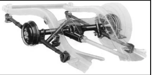
[image:18.595.99.415.191.414.2]In this project, double wishbone suspension had been selected to use by extreme buggy. This due to advantages of this suspension system and it compatibility with extreme buggy chassis. This suspension usually attaches to front or rear wheel where hub assembly attach to the single point and chassis with two points. This will maintain a straight tire during driving and prevent wheel from turn to the side.
Figure 1.1: Double Wishbone Suspension (Speedcunt, 2012)
3
1.2 Problem Statement
Suspension system is the most important thing when designed an extreme buggy car. In recent years, handling stability and ride with a comfort is a very important features when design an off-road vehicle. In off-road terrain, the track consists of all kinds of obstacles that could easily bind up suspension of any buggy car. Thus, to make the buggy more compatible with extreme terrain, it is necessary to design a suspension system that can handle the roughest of bump without affecting vehicle stability and at the same time it provide a smooth ride to the driver and passenger. This mean a strong and tough suspension is needed to build an extreme buggy that suitable for all challenging terrain.
1.3 Objective
Based on the title “Design and Analysis of Suspension System for Extreme Buggy”, the objectives to be achieve at the end of this project are as below :-
To design and analysis suspension system for extreme buggy.
4
1.4 Scope & Limitation
This extreme buggy will be design with two seats for driver and passenger. It must be suitable and practical to be use on a rough and extreme terrain. This buggy will use 1.3 Litre engine from Perodua Kembara. It is 4WD with front mounted engine. This project will use CATIA V5R19 software to design suspension system and produce details child part drawing. Then, by using same software, a structure analysis will be done to analysis it strength and weakness point. After that, a kinematics and compliance analysis will be run to study the movement of each component in buggy suspension. This analysis will done using HyperWorks Motion View. A raw material that will be use is A4 paper for details child part drawing. The requirement that needed to do this project is student must be able to use CATIA V5 and HyperWorks software and know how to run analysis using both software.
To study and design a suitable suspension system for extreme buggy.
To produce details child part drawing for all component in extreme buggy suspension system.
5
CHAPTER 2
LITERATURE REVIEW
2.1 Suspension System
Suspension system is a term given to the set of spring, shock absorber and linkage that connect vehicle to it wheel and allow relative motion between them. Suspension system has two main purpose such as contributing to the vehicle road holding and braking for a good active safety. It also protect the vehicle itself and it cargo from shock load. According to Ramakrishna, K. (2012), suspension system of an automobile is located between the rigid frame and the travel wheels. The frame as well as the body of the vehicle is attached to the front axle and the rear axle. It does the job by absorbing these shock loads and make the ride more comfortable.
2.2 Sprung And Un-Sprung Mass
6
[image:22.595.165.443.214.433.2]In Figure 2.1, it illustrates a line diagram model of total suspension of an automobile. The magnitude of the sprung masses and un-sprung masses are required for the analysis of suspension during the design stage. Depend on these masses, the suspension that consisting shock absorbers and spring are designed. Since the un-sprung mass will always stay as un-un-sprung mass, design should always to be keep the un-sprung mass as low as possible.
7
2.3 Main Types Of Suspension
There a two main types of suspension system that can be found in vehicles. It is independent and dependent suspension. It refers to ability of other wheels to move independently from of each other. While, a dependent suspension system or also call as solid axle is move dependently based on opposite wheel. This suspension system usually found on off-road vehicle and truck. This mean that dependent suspension system wheels are linked to each other. As example, when tire on the left side hit a bump, it directly affected the right side. This will cause a larger effect from original bump. Other disadvantage of dependent system is it weight commonly more compare to independent system. This cause by number of part that require in dependent system but no need in independent system.
8
2.4 Dependent Suspension
According to Gillespie, T. D. (1992), dependent suspension is located at end of the rigid beam so any movement from one wheel will transmitted to opposite wheel. This will cause wheel to steer and camber together. This system usually used by front suspension of heavy trucks that carry massive load. However, dependent suspension has it own advantage where wheel camber is not affect by body roll.
2.4.1 Hotchkiss
[image:24.595.181.428.445.567.2]This suspension system is the most familiar form of the solid drive axle. The axle using semi-elliptic leaf springs as shown in Figure 2.2 and driven through longitudinal driveshaft with universal joint at transmission and axle. The spring is attach longitudinal and connect to chassis at the end while axle is attached near the midpoint. It is the simplest and least expensive of all suspensions. The Hotchkiss system use widely on the rear axle in passenger car in year 1960 and still use by mostly light and heavy truck.