This content has been downloaded from IOPscience. Please scroll down to see the full text.
Download details:
IP Address: 161.139.220.32
This content was downloaded on 06/03/2014 at 02:23
Please note that terms and conditions apply.
TLS for generating multi-LOD of 3D building model
View the table of contents for this issue, or go to the journal homepage for more 2014 IOP Conf. Ser.: Earth Environ. Sci. 18 012064
(http://iopscience.iop.org/1755-1315/18/1/012064)
TLS for generating multi-LOD of 3D building
model
R Akmalia1,4, H Setan1, Z Majid1, D Suwardhi2 and A Chong3
1
Photogrammetry and Laser Scanning Research Group, FGRE, Universiti Teknologi Malaysia, Johor, Malaysia
2
3D Modeling and GIS Research Group, FITB, Institut Teknologi Bandung, Bandung, Indonesia
3
University of Southern Queensland, Queensland, Australia
Email: [email protected]
Abstract. The popularity of Terrestrial Laser Scanners (TLS) to capture three dimensional (3D) objects has been used widely for various applications. Development in 3D models has also led people to visualize the environment in 3D. Visualization of objects in a city environment in 3D can be useful for many applications. However, different applications
require different kind of 3D models. Since a building is an important object, CityGML
has defined a standard for 3D building models at four different levels of detail (LOD). In this research, the advantages of TLS for capturing buildings and the modelling process of the point cloud can be explored. TLS will be used to capture all the building details to generate multi-LOD. This task, in previous works, involves usually the integration of several sensors. However, in this research, point cloud from TLS will be processed to generate the LOD3 model. LOD2 and LOD1 will then be generalized from the resulting LOD3 model. Result from this research is a guiding process to generate the multi-LOD of 3D building starting from LOD3 using TLS. Lastly, the visualization for multi-LOD model will also be shown.
1. Introduction
In the last 10 years, term ‘3D city model’, has become more popular. 3D city model integrates a large number of spatial objects in different classes and different data models and structures. In order to fulfil the requirement for efficient visualization of 3D city model, the new Open Geospatial Consortium (OGC) created CityGML defining 3D city model in five different level-of-details (LOD).
Generating 3D model of building, especially for different LODs (multi-LOD), is an interest topic in surveying. In recent years, huge progress has been made in terms of accuracy and speed in order to obtain and render 3D models of buildings. On the other hand, studies on Terrestrial Laser Scanner (TLS) application as a 3D measurement tools are still increasingly performed. This tool has been established as a new measurement method for fast, area-wide 3D-surveying [1]. It is easy to use TLS, even for a non-expert, though the data processing to generate the model may take a long time. Thus, further research on the process of generating multi-LOD of building model using TLS is required.
4
To whom any correspondence should be addressed.
8th International Symposium of the Digital Earth (ISDE8) IOP Publishing IOP Conf. Series: Earth and Environmental Science18(2014) 012064 doi:10.1088/1755-1315/18/1/012064
Content from this work may be used under the terms of theCreative Commons Attribution 3.0 licence. Any further distribution
of this work must maintain attribution to the author(s) and the title of the work, journal citation and DOI.
2. Terrestrial laser scanner for generating multi-LODs of 3D building model
Three dimension (3D) modelling for building requires a data acquisition which captures a building as 3D object. Beside data capture and 3D modelling process, generalization is one of the processes described in this paper. An approach for generating multi-LODs of building model consist of data capturing using TLS, point cloud processing, and 3D modelling of high level detailed model. To generate the lowered detail of building model, the generalization process of point cloud is conducted for generating lowered detail point cloud.
2.1. Scanning building using TLS
Previous works using TLS for building modelling were described in [2] and [3] although they still integrate TLS with other method such as close range photogrammetry. Using TLS, scanning process for generating the point cloud of building is the first step. The system inside TLS is described in [4]. It is grouped into some categories. Usually, time-of-flight (TOF) and phase difference are used for capturing large object like building. Meanwhile, other TLS system such as triangulation is used for close-range scanning.
Scanning process resulting million points called point cloud. Generally, every point in the point clouds was referenced to the local coordinate system with the laser as the origin [5]. Registration process is required to combine point clouds from different scan positions. The process basically is a 3D Helmert transformation without the scale factors. Figure 2.1 illustrates the transformation several scan positions into one coordinate system.
Figure 1. Transformation of local coordinate system [5].
2.2. 3D Modelling from point cloud data
Computer-Aided Design (CAD) is the common tool for representation of 3D model. It is usually used for visualization of geometric aspects in 3D model. In the field of 3D City Modelling, there are three categories of approaches that are usually used for reconstructing building model [6]. These are reconstruction based on DSM simplification, segmentation of point cloud, and parametric shapes. Usually, point cloud data from TLS will be processed using segmentation.
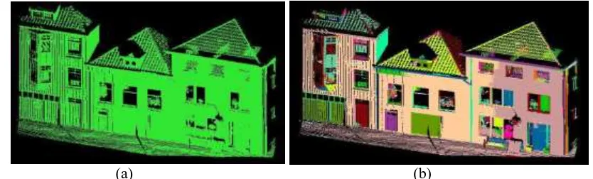
This process of segmentation groups points into segments, based on their relationship such as corresponding surface and normal direction. Elaboration about segmentation of point cloud can be referred to [7]. Figure 2.2 shows the different between point cloud before and after segmentation process. Related work using 3D Hough transform for auto-detecting and segmentation roof faces shows that this approach is suitable for reconstructing simple building with flat or gable roofs but fails on more detailed larger building [8].
8th International Symposium of the Digital Earth (ISDE8) IOP Publishing IOP Conf. Series: Earth and Environmental Science18(2014) 012064 doi:10.1088/1755-1315/18/1/012064
(a) (b)
Figure 2. (a) point cloud before segmentation (b) point cloud after segmentation process.
2.3. Multi-lod for 3d model of building
Representing 3D city models in multi-LOD open the possibility of multi-scale visualization. It leads to an efficient visualization of 3D city models since different applications might require different scale of model. Standards are already created in order to store, manage, and integrate 3D models from different sources and scales correctly. CityGML, VDI 3805, and Industrial Foundation Class (IFC) are the examples of the standard [9]. However, for 3D city modelling, CityGML is the common standard used for representing object both in large scale model and detailed model since the model can be ordered by its LODs. Other standards used to represent multi-scales models such as VDI 3805 and IFC models are designed for more detailed level.
[image:4.596.86.503.117.243.2]CityGML is an open data model for storage and exchange of 3D city models [9]. It provides a method for storing and managing both geometric and semantic information of 3D model. Through CityGML, building model is represented in 5 LODs, start from LOD0 to LOD4. It is proposed to decrease the complexity of 3D models. Higher LOD shows more detailed and accurate model as shown in Figure 2.3. As for the detail of standards for each LOD are described in Table 2.1.
Figure 3. Five different LODs defined in CityGML.
Table 1. Definition of LOD.
Features LOD0 LOD1 LOD2 LOD3 LOD4
Area Regional City/regional District Individual
building Architectural model Standard Accuracy Less than LOD1
5 / 5 m 2 / 1 m 0.5 / 0.5 m 0.2 / 0.2 m
Generalized
object
Classification
according to land use
> 6*6 m >4*4m > 2*2m Constructive elements
and
openings are
represented Building
Parts
- - - External
structures
Real form
Roof Projection
- Flat Roof type
and
orientation
Real object form Real object form
Several simplification methods have been proposed to obtain lower LODs from higher LODs automatically. From previous works, LOD1 and LOD2 of building model can be generated gradually using semi-automatic method from LOD3. Basically, in deriving the building surface, the entire opening object in building exterior like windows and doors must be removed [11]. This concept is applied for generating LOD2 from LOD3. The process of generalization from LOD2 to LOD1 is almost the same with the generalization from LOD3 to LOD2. However, in LOD1, roof structure is represented as a flat roof. The different structural entities of a building are aggregated to simple blocks and not differentiated in detail. Entire building installations will be eliminated. Afterward, the footstep of the outer building surface will be generalized.
3. Methodology
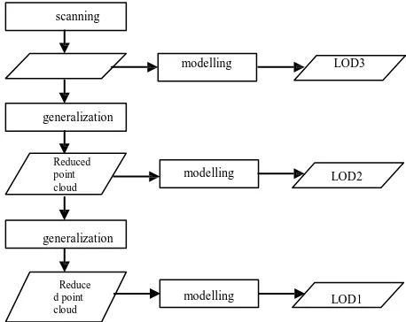
Working flow is divided into scanning, 3D modelling, and generalization, as can be seen in Figure 3.1.
scanning
modelling LOD3
generalization
Reduced point cloud
modelling LOD2
generalization
Reduce d point cloud
modelling LOD1
Figure 4. Diagram of work process.
8th International Symposium of the Digital Earth (ISDE8) IOP Publishing IOP Conf. Series: Earth and Environmental Science18(2014) 012064 doi:10.1088/1755-1315/18/1/012064
[image:5.596.152.381.472.654.2]Previous works used footprint from LiDAR data to generate building in LOD1 and used photogrammetry to generate LOD3 and LOD2. However, in this research, TLS is used to generate model in LOD1, LOD2, and LOD3.
The scanning process is following the suggestion of [5] and [4]. Point clouds resulted from the scanning process are in the high density quality. This point cloud is detail enough to generate a building model in LOD3. Afterwards the point cloud is generalized using segmentation method. This method is to reduce the point cloud to be ready for generating a building model in LOD2. The same method of generalization is repeated to reduce point cloud for generating LOD1. To reconstruct the building using the point cloud, it is using the detail requirement specified in the Table 2.1. Method for reconstructing point cloud into surface model of building is using digitations of point cloud.
4. Implementation
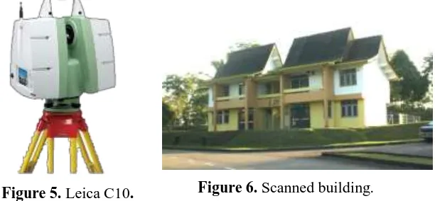
Data collection was conducted using TOF TLS, Leica C10. The TLS was used to scan a building inside UTM Campus area. The building is a student resident. During 4 hours, the TLS was capable to scan the whole building from five scan positions. Figure 4.1 shows the TLS used for capturing the building in Figure 4.2.
Scan stations were placed around the building with the distance around 10-20 meters from the building surface. In every scan station, it took around 30 minutes to scan and get the panoramic photo with medium resolution. Although the scanning process only took 30 minutes, as the scanner was levelled in each scan stations, it took another 10 minutes for mobilization from one scan station to another and set up the scanner. In every scan station, the overlap area from one scan station to another was also maintained over than 50% in order to get better accuracy, following the suggestion from [5].
Figure 5. Leica C10. Figure 6. Scanned building.
Point cloud processing was done using Cyclone software from Leica. Point clouds from all scan stations were registered and filtered resulting point cloud as shown in Figure 4.3. Manual registration or point-to-point registration was done since the special target was not automatically detected by the software. Using this method, registration can only be done by peering 2 scan stations only. From the experience, the result from the registration process had 0.003 error value in Cyclone. According to manual for Cyclone’s user, this value is considered as acceptable.
Figure 7. Registered point cloud. Figure 8. Reduced point cloud.
[image:6.596.149.455.407.549.2] [image:6.596.101.489.638.761.2]Detailed point cloud was used to generate a building model in LOD3. Modelling process was conducted in Sketch Up. Before the modelling process, the point cloud first was reduced in Cyclone to by eliminating opening such as window and doors for generating LOD2. Figure 4.4 shows the reduced point cloud in Sketch Up. The reduced point cloud were further reduced and generalized in order to model the building in LOD1.
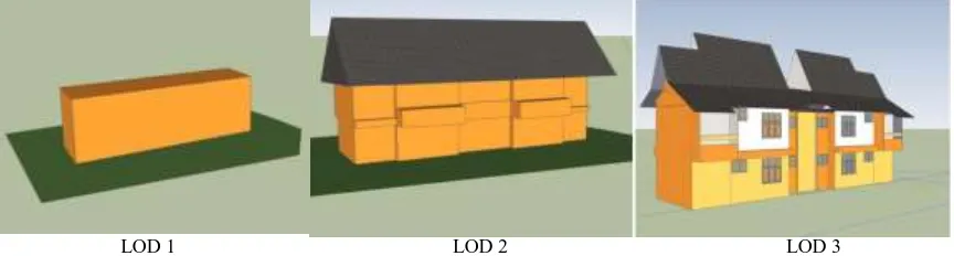
Results from this preliminary result were the LOD1, and 2 of 3D building models using manual 3D modelling, shown in Figure 4.5. In LOD1, the building model was represented in a block model. The height is following the highest wall of building and the width is following the footprint of point cloud. In LOD2, the real structure of building was represented, including the roof. However, a more detailed model was represented in LOD3 where windows and doors were also included.
[image:7.596.80.512.249.365.2]LOD 1 LOD 2 LOD 3
Figure 9. Resulted model in LOD 1, LOD 2, and LOD 3.
5. Conclusion
The use of TLS for 3D city model application is possible. It can be used for generating multi-LOD of building model. The aim of the research to apply this instrument for generating multi-LOD can be achieved. Resulted point cloud is detail enough to capture details on building facade. Although the data acquisition using this method only takes several hours, data processing using this method still significant effort, especially to convert point cloud into 3D model.
According to this experiment, working hours in the field and laboratory using TLS was 1:4 to create the 3D model of building in multi-LOD. 3D building models resulted from this experiment can be used for 3D city model application since the models are already constructed following the requirement defined by CityGML. Since the generalization of point cloud process was done using manual reduce in cyclone, further research should develop method to do point cloud generalization using auto or semi-auto segmentation and generalization.
However, from this experiment, scanning of building was only conducted for exterior of building. Thus, only LOD 1, LOD 2, and LOD 3 are generated. For further research will be useful if the scanning process can also covers the interior of building to generate LOD 4.
References
[1] Zogg, H. M. 2008 Investigations of High Precision Terrestrial Laser Scanning with Emphasis on the Development of a Robust Close-Range 3D-Laser Scanning System(Vol. DISS. ETH. NO. 18013). Zurich: ETH Zurich
[2] Radosevic, G. 2010 Laser Scanning Versus Photogrammetry Combined with Manual Post- modelling in Stecak Digitization. The 14th European Seminar on Computer Graphics.
[3] Ashawabkeh, Y. 2006 Integration of Laser Scanning and Photogrammetry for Heritage Documentation. Stuttgart: Institut fur Photogrammetry der Universitat Stuttgart
[4] Schulz, T. 2007 Calibration of a Terrestrial Laser Scanner for Engineering Geodesy (Vol. DISS. ETH No. 17036). Zurich: ETH
[5] Reshetyuk, Y. 2009 Self-Calibration and Direct Georeferencing in Terrestrial Laser Scanning. Stockholm: Royal Institute of Technology
[6] Haala, N., & Kada, M. 2010 An Update on Automatic 3D Building Reconstruction. ISPRS
Journal of Photogrammetry and Remote Sensing 570-580
8th International Symposium of the Digital Earth (ISDE8) IOP Publishing IOP Conf. Series: Earth and Environmental Science18(2014) 012064 doi:10.1088/1755-1315/18/1/012064
[7] BICT, T. C. 2012 Footprint Decomposition Combined with Point Cloud Segmentation for Producing Valid 3D Models. Master of Science Thesis, Delft University of Technology, OTB Research Institute for the Built Environment, Delft
[8] Pu, S., & Vosselman, G. 2009 Automatic Extraction of Building Features from Terrestrial Laser Scanning. ISPRS Journal of Photogrammetry and Remote Sensing
[9] Mao, B. 2011 Visualisation and Generalisation of 3D City Model. Stockholm: Royal Institute of Technology (KTH)
[10] OGC. 2012, April 4 CityGML. (G. Groeger, T. H. Kolbe, C. Nagel, & K.-H. Haefale, Eds.) Retrieved September 12, 2012, from OGC: http://www.opengis.net/spec/citygml/2.0
[11] Fan, H., & Meng, L. 2012 A Three-Step Approach of Simplyfying 3D Buildings Modeled by CityGML. International Journal of Geographical Information Science , 6 (26), 1091-1107. [12] Albert, J., Bachmann, M., & Hellmeier, A. 2003 Zielgruppen und Anwendungen für Digitale
Stadtmodelle und Digitale Geländemodelle.Retrieved 9/9, 2012, from Universitaet Bonn
Web Site:
http://www.ikg.uni-bonn.de/fileadmin/sig3d/pdf/Tabelle_Anwendungen_Zielgruppen.pdf
[13] Groeger, G., & Pluemer, L. 2012, May CityGML - Interoperable Semantic 3D City Models.
ISPRS Journal of Photogrammetry and Remote Sensing 71 , 12-33