DESIGN & IMPLEMENTATION OF AUTOMATED FILLING AND CAPPING MACHINE USING PLC
MOHD ASNAWI BIN SAIMON
“I hereby declared that I have read through this report and found that is has comply the partial fulfillment for awarding the degree of Bachelor of Electrical Engineering
(Control, Instrumentation & Automation)
Signature ; ______________________________________ Supervisor’s Name : ENCIK MOHD ARIFF BIN MAT HANAFIAH
DESIGN AND IMPLEMENTATION OF AUTOMATED FILLING AND CAPPING MACHINE USING PLC
MOHD ASNAWI BIN SAIMON
Thesis submitted in accordance with the partial requirements of the Universiti Teknikal Malaysia Melaka for the Degree of Bachelor in Electrical Engineering
(Control, Instrumentation and Automation)
Fakulti Kejuruteraan Elektrik Universiti Teknikal Malaysia Melaka
DECLARATION
I hereby, declare this thesis entitled “Design & Implementation of Automated Filling and Capping Machine using PLC” is the result of my own research and design
except as cited in the references.
DEDICATION
ACKNOWLEDGEMENTS
Alhamdulilah, firstly I am grateful to almighty Allah S.W.T because at last I have finished my Bachelor Degree Project 2 (PSM 2) and my report without any problem. It is difficult to finish this Bachelor Degree Project 2 (PSM 2) report without the help.
Secondly, I would like to thank to my beloved family because an actuation and moral support since I was studying in UTeM. My supervisor En. Mohd Ariff bin Mat Hanafiah because giving me a lot of advices and ideas and automatically improve my knowledge and skills in industrial automation. Also thanks to the technician from Pneumatic and PLC Lab which have given the ideas and technical support in completing this PSM 2 project.
ABSTARCT
ABSTRAK
TABLE OF CONTENT
CHAPTER CONTENT PAGE
DECLARATION i
DEDICATION ii
ACKNOWLEDGEMENTS iii
ABSTRACT iv
ABSTRAK v
TABLE OF CONTENT vi
LIST OF FIGURE ix
LIST OF TABLE xii
1 INTRODUCTION
1.1 Introduction 1
1.2 Project Overview 1
1.3 Problem Statements 2
1.4 Objectives of the Project 2
1.5 Scope of the Project 2
2 LITERITURE REVIEW
2.1 First Review: Vibrac® Low Volume Capper 4
2.1.1 Standard features 5
2.2 Second Review: Automatic Gravity Filler GI 2100 5
2.2.1 Construction features 6
2.2.2 Control panel features 6
2.2.3 Main components feature 6
2.2.4 Standard features 6
2.2.5 Requirements 7
2.3 Third Review: Filling Concept 7
2.4 Conclusion 8
CHAPTER CONTENT PAGE
2.5.1 Programmable Logic Controller (PLC) 8
2.5.1.1 Introduction 8
2.5.1.2 Basic operation of PLC 9
2.5.1.3 Advantages of PLC 10
2.5.1.4 Programming languages 10
2.5.2 DC Electrical Motor 13
2.5.2.1 Basic Construction 13
2.5.2.2 Basic DC Motor Operation 14
2.5.2.3 Types of DC Motors 15
2.5.3 Sensing Devices 18
2.5.4 Belt Conveyors 20
2.5.5 Pneumatic Cylinder 21
2.5.6 Pneumatic Solenoid Valve 22
2.5.7 Feed Valve (Flow Valve) 23
3 PROJECT BACKGROUND
3.1 Project Background 24
3.2 System Concept and Algorithm 25
3.2.1 Station 1: Bottle Loading 25
3.2.2 Station 2: Filling Process 26 3.2.3 Station 3: Capping Process 27
4 METHODOLOGY
4.1 Methodology of the project 31
4.2 Project Implementation 32
4.2.1 Design and Drawing 32
CHAPTER CONTENT PAGE
4.2.4.3 The Conveyor 38
4.2.4.4 Pneumatic System Equipment 39
4.2.4.5 Feed Valve 41
5 RESULT
5.1 Hardware Implementation 42
5.2 Software Implementation 45
5.2.1 I/O Assignment 45
5.2.2 PLC Programming 48
5.2.3 Pneumatic Connection Diagram 59
5.3 Analysis 62
5.3.1 Parameters 62
5.3.1.1 Loading Section 62
5.3.1.2 Filling Section 62
5.3.1.3 Capping Section 62
5.3.2 Cycle Time 63
6 DISCUSSION AND RECOMMENDATION
6.1 Discussion 64
6.2 Problem Encountered 64
6.2.1 Mechanical 64
6.2.2 Electrical 65
6.2.3 Pneumatic 65
6.3 Recommendation 66
7 CONCLUSION
7.1 Conclusion 67
LIST OF REFERENCES 68
GANTT CHART 69
FIGURE TITLE PAGE
2.1 Capping Machine 4
2.2 Filling Machine 5
2.3 Time Gravity Filler 7
2.4 Application of PLC 8
2.5 PLC Process Block Diagram 9
2.6 Ladder Diagram 10
2.7 Grafcet 11
2.8 Basic Construction of DC Motor 13
2.9 Permanent Magnet DC Motor Diagram 15
2.10 Series DC Motor Diagram 16
2.11 Shunt DC Motor Diagram 17
2.12 Compound DC Motor Diagram 17
2.13 Type of Sensor 18
2.14 Belt Conveyor 20
2.15 Pneumatic Cylinders 21
2.16 Solenoid Valves 22
2.17 Feed Valve 23
3.1 Designed System 24
3.2 Loading Process 26
3.3 Filling Process 26
3.4 Capping Process 27
3.5 System Algorithm Flow Chart 28
3.6 System Algorithm Flow Chart (continued) 29 3.7 System Algorithm Flow Chart (continued) 30
4.1 Hardware Implementation 32
4.2 Software Implementation 33
4.3 Flow Chart of the Project Methodology 34
4.4 Omron CQM1H PLC 35
FIGURE TITLE PAGE
4.6 The DC Motor used in the System 37
4.7 The Location of the Motor in the System 37 4.8 The Conveyor and the Mounted DC Motor 38 4.9 The Gear Mounted between the Motor and the
Conveyor Roller 38
4.10 Pneumatic Equipments 39
4.11 3/2 Way Single Acting and 5/2 Way Double Acting
Directional Control Valve 40
4.12 Double Acting Cylinder 40
4.13 Feed Valve Mounted Below the Filling Tank 41
5.1 Front View 42
5.2 Side View 43
5.3 Top View 43
5.4 Back View 43
5.5 Loading Section 44
5.6 Filling and Capping Section 44
5.7 Typical I/O Connection 47
5.8 The Ladder Diagram 48
5.9 The Ladder Diagram (continue) 49
5.10 Rung 0 50
5.11 Rung 1 51
5.12 Rung 2 51
5.13 Rung 3 52
5.14 Rung 4 53
5.15 Rung 5 53
5.16 Rung 6 54
5.17 Rung 7 54
5.18 Rung 8 55
5.19 Rung 9 55
5.20 Rung 10 56
5.21 Rung 11 56
5.23 Rung 13 57
5.24 Rung 14 58
5.25 Pneumatic Diagram Loading Process 59
5.26 Pneumatic Diagram Cap Pusher Process 60
LIST OF TABLE
TABLE TITLE PAGE
2.1 Sensor Advantages and Disadvantages 19
5.1 Input I/O Assignment 45
5.2 Output I/O Assignment 46
5.3 Internal Relay Assignment 46
5.4 Timer Assignment 46
CHAPTER 1
INTRODUCTION
1.1 Introduction
In this modern era, the entire industrial task has become dependant to the automation. Automation system has taken over the conventional method to complete the process. Automation becoming increasingly important in the manufacturing process because computerized machine are capable of handling repetitive tasks quickly and efficiently. Machines used in industrial automation are also capable of completing any tasks that are not capable to human workers. In this project, machine with automation system is used to do the filling and capping process. It also will reprise as a training kit to describe the process of filling and capping using the combination of DC electrical motor and pneumatic system that are controlled by PLC (Programmable Logic Controller).
1.2 Project Overview
fabricating process, while electrical part consists of electrical drawing, electrical wiring and programming.
1.3 Problem Statements
This machine is designed to combine the filling and capping process in a single machine. This project will reduce the usage of man power because all of the work will be done by machine. Human held filling process will cause inexact volume of liquid into the bottle. So using automated system will set the volume of the liquid exactly the same for each bottle. Human cannot give the enough pressure to cap the bottle, so it will use the high pressure mechanism to press the cap on the bottle. If all the process is done manually, it will cost lot of time to complete the task. This machine will also reduce the human error while doing this process manually. It also can be used as a training kit to describe the function of dc motor and pneumatic system.
1.4 Objectives of the Project
The project is aimed to meet the following objectives:
To design and implement automated filling and capping machine
To learn the concept of pneumatic system, electrical DC motor system
To implement hardware installation, wiring, mechanical mounting
To learn troubleshooting and analyzing
To learn PLC programming
1.5 Scope of the Project
All projects have their own scope or limitation as a guideline throughout the completion of the project. The project scope for the implementation of this project is:
structure, dc motor electrical system, pneumatic system, PLC and sensing device. The PLC will be the main controller for the system.
CHAPTER 2
LITERATURE REVIEW
This chapter will explain and discuss about source or article that related to the project. It is consist of the products that have been appeared in the market nowadays. This chapter is also contained the theory of the components, equipments and programming languages that is used in the project.
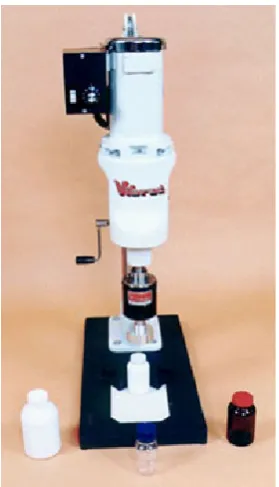
[image:19.595.250.390.421.665.2]2.1 First Review: Vibrac® Low Volume Capper
The Vibrac® Low Volume Capper bench top system is designed to provide years of trouble free capping and de-capping of threaded bottles up to 15 inches in height. In a matter of minutes, the machine may be adjusted for different containers. The height is adjusted by means of a hand cranked rack and pinion assembly. Production rates of 10 to 30 units per minute are typically achieved. So whether the application is in a start up operation, a rework station, a laboratory or a low volume manufacturing plant, the Low Volume Capper can meet the requirements.
Sturdy, low maintenance construction.
Precise torque control with a permanent magnet clutch.
Quick container and cap changeover.
Both foot-operated and fixture actuated cycling.
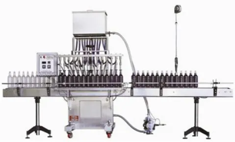
[image:20.595.200.440.488.633.2]2.2 Second Review: Automatic Gravity Filler GI 2100
2.2.1 Construction features
304 Stainless steel heavy duty stainless steel welded C frame. It has 20 Gallon stainless steel overflow tank and stainless steel cover for overflow tank. It also consist 20 Gallon feeding tank with float valve and stainless steel cover for feeding tank. The 20 hose are made with 304 stainless steel feeding manifold. All contact parts are stainless steel, sanitary, Teflon, viton and hoses. The machine is mounted on 4 heavy duty casters. The machine is leveled by 1 inch 304 stainless steel leveling screws.
2.2.2 Control panel features
The machine was controlled by Omron PLC for all logic functions, special modifications on programs available for special adaptations. Front panel filling time adjustment through Omron Timer. Front panel conveyor speed control for machine sold with conveyor. Front panel mounted bottle counter. Front panel Start and Emergency STOP for easy access. Front panel nozzle code for changing nozzle quantities. The fiber optic sensors are set by Omron standard for container gating. It was expandable to 20 nozzles to increase speed.
2.2.3 Main components feature
This machine uses 40 Gallon per minute double diaphragm pump for feeding tank supply. Hardened Stainless steel calibrated shafts with linear bearings for nozzle rack movement smoothness and durability. It has 8 inch stroke air cylinder with magnetic sensors for nozzle up and down movement. Hand wheel and shaft mounted stoppers for height and stroke adjustment.
2.2.4 Standard features
float on tank are mounted on the pump. Spacing and additional bottle control obtained by flow controls mounted on air gating cylinders.
2.2.5 Requirements
110 Volts, 60Hz, 15 Amp and 10 CFM @ 80 p.s.i.
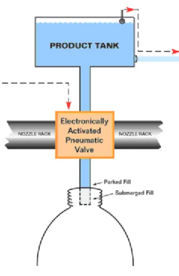
[image:22.595.232.410.309.583.2]2.3 Third Review: Filling Concept
Figure 2.3: Time Gravity Filler
2.4 Conclusion
After reviewing all the review above, it is true that there are many modern filling machine and capping machine in the market. The machine equipped with latest technology of hardware that can perform the given task efficiently with almost no errors. The project is trying to combine the two systems above into one system that operates sequel one after another. The project only includes the basic concept of filling and capping system compared to the real machine. It is suitable for teaching process as a training kit.
2.5 Theory
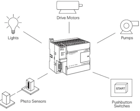
2.5.1 Programmable Logic Controller (PLC)
2.5.1.1 Introduction
[image:23.595.202.440.541.730.2]A programmable logic controller (PLC) is a digital electronic device that uses a programmable memory to store instructions and to implement functions such as logic, sequencing, counting, and arithmetic in order to control machines, processes, and has been specifically designed to make programming easily.
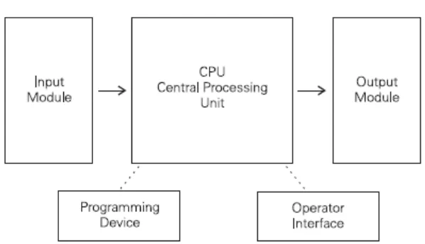
PLCs consist of input modules or points, a Central Processing Unit (CPU), and output modules or points. An input accepts a variety of digital or analog signals from various field devices (sensors) and converts them into a logic signal that can be used by the CPU. The CPU makes decisions and executes control instructions based on program instructions in memory. Output modules convert control instructions from the CPU into a digital or analog signal that can be used to control various field devices (actuators). A programming device is used to input the desired instructions. These instructions determine what the PLC will do for a specific input. An operator interface device allows process information to be displayed and new control parameters to be entered.