City, University of London Institutional Repository
Citation:
White, M. ORCID: 0000-0002-7744-1993, Read, M. G. and Sayma, A. I. (2018). Optimisation of cascaded organic Rankine cycle systems for high-temperature waste-heat recovery. Paper presented at the ECOS 2018 - The 31st International Conference onEfficiency, Cost, Optimization, Simulation and Environmental Impact of Energy Systems, 17 - 22 June 2018, Guimarães, Portugal.
This is the accepted version of the paper.
This version of the publication may differ from the final published
version.
Permanent repository link:
http://openaccess.city.ac.uk/20094/Link to published version:
Copyright and reuse: City Research Online aims to make research
outputs of City, University of London available to a wider audience.
Copyright and Moral Rights remain with the author(s) and/or copyright
holders. URLs from City Research Online may be freely distributed and
linked to.
PROCEEDINGS OF ECOS 2018 - THE 31ST INTERNATIONAL CONFERENCE ON
EFFICIENCY, COST, OPTIMIZATION, SIMULATION AND ENVIRONMENTAL IMPACT OF ENERGY SYSTEMS JUNE 17-22, 2018, GUIMARÃES, PORTUGAL
Optimisation of cascaded organic Rankine cycle
systems for high-temperature waste-heat recovery
Martin T. White*, Matthew G. Read, and Abdulnaser I. Sayma
Department of Mechanical Engineering and Aeronautics,
City, University of London, Northampton Square, London, United Kingdom, EC1V 0HB
*Corresponding author: martin.white@city.ac.uk
Abstract:
The selection of an optimal working fluid and the design of the system components for a small-scale (<100 kW) high-temperature (250 – 400 °C) organic Rankine cycle (ORC) can be challenging owing to the possibility of sub-atmospheric condensation pressures and high expander volume-ratios. The latter means that volumetric expanders are not suitable, whilst a single-stage turbine would be characterised by supersonic flow and small blade heights. Alternatively, a cascaded cycle can be considered, in which the heat-rejection from a topping cycle drives a bottoming cycle. Through the proper selection of working fluids for the two cycles, sub-atmospheric condensation pressures can be avoided, whilst the volume-ratio is divided across two separate expansions. Moreover, two-phase expansion in the topping cycle can be considered to increase the power output from the system. At present, there are limited guidelines for the selection of fluids for each cycle. In this paper, the development of a novel method to identify the optimal pairing of fluids for cascaded ORC systems is discussed. The model is comprised of a cascaded ORC thermodynamic model and the Peng-Robinson equation of state. Using this equation of state allows the fluid parameters to be included within the optimisation, which allows the identification of optimal fluid parameters for both the topping and bottoming cycles, alongside the optimal operating conditions. The model has been used to identify optimal fluids for cascaded systems for heat-source temperatures ranging between 250 and 400 °C. The results have been verified by separate optimisation studies completed using REFPROP. Finally, a comparative study has shown that optimal cascaded systems can achieve similar power outputs to simple ORC systems and have lower expander volumetric ratios. However, cascaded systems require larger heat exchangers. The performance of cascaded systems could be further improved through two-phase expansion, and this should be studied in the future.
Keywords:
Cascaded ORC; Organic Rankine cycle; Waste-heat recovery; Working-fluid selection
1. Introduction
Organic Rankine cycles (ORC) are considered to be a suitable technology for the conversion of heat sources at temperatures between 80 and 400 °C into mechanical power, and the technology has already been commercialised across a range of power outputs [1]. Most of these systems operate a simple organic Rankine cycle, which is comprised of a pump, evaporator, expander and condenser. Whilst this has the advantage of simplicity, the use of this simple configuration can introduce challenges with regards to working-fluid selection and component selection as the heat-source temperature increases.
Generally speaking, the optimal working fluid for a particular application is linked to the heat-source temperature, with high-temperature heat sources requiring working fluids with high critical temperatures [2]. However, a correlation between the normal-boiling temperature of a working fluid and its critical temperature is also observed [3], and therefore the normal-boiling temperature can also be expected to increase as the heat-source temperature increases. In this instance, either the thermodynamic performance of the cycle is penalised by operating the system with a high condensation temperature to avoid sub-atmospheric condensation pressures, or system costs are increased through the need to have a physically large condenser owing to large volumetric-flow rates, which must also operate under a vacuum.
other hand, whilst turbo-expanders can accommodate much larger volume ratios across a single stage, the significant change in the density through the turbine leads to small rotor-inlet blade heights, particularly for small-scale applications [5], which can reduce turbine efficiency through increased secondary flow and tip-clearance losses. Moreover, high expansion ratios mean that supersonic conditions are experienced within the stator, further complicating the turbine design process. Arguably, the challenges associated with a single-stage turbo-expander could be circumvented through a suitable two-stage design, although the large volumetric flow-rate at the expander outlet may still lead to physically large systems. It is also interesting to note that two-phase expansion presents an opportunity to produce higher power outputs from waste-heat sources, compared to a superheated expansion [4,6]. However, turbo-expanders cannot currently accommodate two-phase conditions at the expander inlet. In this instance, two-phase expansion for high-temperature heat sources cannot be considered when using a simple ORC system. One alternative to a simple ORC system is the cascaded ORC system, in which a high-temperature topping cycle and a low-temperature bottoming cycle are coupled together. Kane et al. [7] developed an experimental setup of a cascaded ORC system, driven by solar energy and waste-heat, whilst Kosmadakis
et al. [8] assessed the use of a cascaded ORC system for reverse osmosis desalination. Both authors comment on the potential promise of such systems, but consider relatively low temperatures (< 200 °C). However, one the of the advantages of the cascaded system is that different working fluids can be used in the topping and bottoming cycles, which means higher temperature heat-sources could be effectively converted without introducing sub-atmospheric pressures. Furthermore, by optimising the working fluid in each cycle respectively it may be possible to achieve a better thermodynamic performance than an equivalent simple ORC system, and since the pressure ratio experienced by a single-stage system is essentially divided across the two cycles, expander design is less challenging. Moreover, since the expansion volume ratio is also reduced, it becomes possible to consider screw-expanders for one, or both, of the expansion processes, which could mean two-phase expansion could be used in one of the cycles to further improve the performance of the system [9,10].
Working-fluid selection for simple ORC systems has been the focus of many previous research studies; as such selection guidelines are relatively well defined within the literature [11,12]. Moreover, the application of computer-aided molecular design (CAMD) is becoming more widespread in the search for new ORC working fluids [13-15]. In these studies, the molecular structure of the working fluid is optimised alongside the cycle conditions, thus reducing the design process to a single optimisation. In comparison, to the authors’ knowledge, the optimal selection of working fluids for a cascaded ORC system has received limited attention. Hence, the aim of this paper is to apply principles taken from CAMD to the study of cascaded ORC systems. More specifically, a cascaded ORC system model, coupled to the Peng-Robinson equation of state, is described and applied to different heat-source temperatures. For each heat-source temperature, the working-fluid parameters for both the topping and bottoming cycles are optimised alongside the cycle operating conditions and optimal working fluids for cascaded ORC systems are identified. Finally, these optimal systems are compared to simple ORC systems for the same heat-source temperatures. Within this study, the method is demonstrated for superheated ORC cycles. However, future extension to allow two-phase expansion will mean high-temperature, cascaded systems with two-phase expansion can also be evaluated.
2. Description of the model
2.1. Peng-Robinson equation of state
To model the respective working fluids in the topping and bottoming cycles the Peng-Robinson equation of state is used, which is defined as:
𝑝 =𝑉𝑅𝑇 &− 𝑏−
𝑎𝛼(𝑇) 𝑉&-+ 2𝑏𝑉
&− 𝑏- , (1)
depend on the critical temperature 𝑇23 and critical pressure 𝑝23. The function 𝛼(𝑇) introduces a temperature dependence to the term on the right-hand side of (1), and this term is dependent on the acentric factor 𝜔. For brevity, the full details of these parameters are not reported here but can be found in [16]. Alongside (1), a second-order polynomial function is used to describe the ideal specific-heat capacity as a function of temperature:
𝑐6,78(𝑇) = 𝐴 + 𝐵𝑇 + 𝐶𝑇- , (2)
where 𝐴, 𝐵 and 𝐶 are constants for a particular fluid. From (1) and (2) the enthalpy ℎ in J/mol, and entropy
𝑠 in J/(mol K) can be determined after some further calculation.
Ultimately, combining the Peng-Robinson equation of state with a second-order polynomial means a potential working fluid can be defined by six parameters, namely, 𝑇23, 𝑝23, 𝜔, 𝐴, 𝐵 and 𝐶. Moreover, by allowing these parameters to become variables during a cycle optimisation study, it is possible to optimise the working fluid in addition to the thermodynamic cycle parameters. This is something that cannot be completed using more advanced property-prediction methods, such as NIST REFPROP [17]. Previous studies have demonstrated the suitability of the Peng-Robinson equation of state for modelling ORC systems [18,19].
2.2. Cascaded ORC thermodynamic model
In this study, the cascaded system is comprised of two sub-critical, non-recuperated cycles, and the expansion processes are assumed to be in the superheated region (i.e., two-phase expansion is not considered). Moreover, pressure drops and heat losses are neglected, and the pumps and expanders are modelled with fixed isentropic efficiencies of 𝜂?= 70%, and 𝜂@= 80% respectively. A
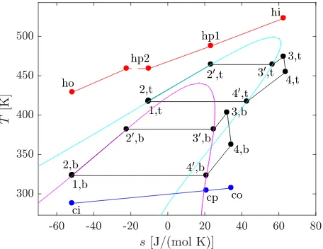
[image:4.595.177.405.419.595.2]temperature-entropy (T-s) diagram of the system is shown in Fig. 1, in which the notation used to describe the system is also defined.
Fig. 1. Schematic of the cascaded ORC system and the notation used to describe it.
As shown in Fig. 1, the waste-heat source is used to preheat, evaporate and superheat the working fluid in the topping cycle. Since the temperature of the heat-source at the outlet of the topping-cycle preheater will be higher than the evaporation temperature of bottoming cycle, it is assumed that the waste heat can also be used to preheat the working fluid in the bottoming cycle. The evaporation and superheating of the fluid in the bottoming cycle is achieved via the heat rejection from the topping cycle.
For this system, seven cycle variables are defined. Firstly, the bottoming-cycle condensation temperature
𝑇A,B defines the condensation pressure and the pump inlet conditions for the bottoming cycle (ℎA,B, 𝑠A,B). Moreover, the bottoming-cycle reduced evaporation pressure 𝑝3,B defines the evaporation temperature
Δ𝑇FGD = 𝑇A,D− 𝑇-,B , (3)
whilst the topping-cycle reduced evaporation pressure 𝑝3,D is also defined as an input. The topping-cycle amount of superheat Δ𝑇FH,D then means the expander inlet conditions can be determined (ℎI,D, 𝑠I,D), and
the imposed pump and expander efficiencies mean the pump outlet conditions (ℎ-,D, 𝑠-,D) and expander outlet conditions (ℎJ,D, 𝑠J,D) can be determined.
The working-fluid mass-flow rate in the topping-cycle 𝑚̇D is found by applying an energy balance to the evaporator:
𝑚̇D = M𝑚̇𝑐6NHM𝑇H7− 𝑇H?AN ℎI,D− ℎ-C,D ,
(4)
where M𝑚̇𝑐6N
H is the heat-source heat-capacity rate in kW/K, 𝑇H7 is the heat-source inlet temperature in
K, and 𝑇H?A is the heat-source temperature at the start of evaporation, and is defined by the pinch-point temperature difference, which is defined as a model input:
𝑃𝑃H= 𝑇H?A− 𝑇-C,P . (5)
The working-fluid mass-flow rate in the bottoming-cycle 𝑚̇B is found by applying an energy balance to
the bottoming-cycle preheater:
𝑚̇B =M𝑚̇𝑐6NHM𝑇H?-− 𝑇HRN ℎ-C,B− ℎ-,B ,
(6)
where 𝑇HR is the heat-source outlet temperature, which is final of the seven cycle variables, and 𝑇H?- is the heat-source temperature at the outlet of the topping-cycle preheater, which is found by applying a similar energy balance to (6) to the topping-cycle preheater.
The expander inlet conditions for the bottoming-cycle (ℎI,B, 𝑠I,B) are found by applying an energy balance to the topping-cycle desuperheating/condensation process, and the bottoming-cycle evaporation/superheating process:
ℎI,B = ℎ-C,B+𝑚̇DMℎJ,D− ℎA,DN
𝑚̇B , (7)
and the expander outlet conditions (ℎJ,B, 𝑠J,B) are found using the imposed expander efficiency.
A final energy balance is then applied to the bottoming-cycle condenser to determine the heat-sink outlet temperature:
𝑇2R= 𝑇27+𝑚̇BMℎJ,B − ℎA,BN M𝑚̇𝑐6N
2
, (8)
where 𝑇27 is the heat-sink temperature in K and M𝑚̇𝑐6N
2 is the heat-sink heat-capacity rate in kW/K. The
condenser pinch point is an output from the model, but a constraint is applied during optimisation to ensure this is not below a minimum allowable value.
The thermodynamic performance of the cycle can be evaluated from the net power output:
𝑊̇T = 𝑊̇T,D+ 𝑊̇T,B = 𝑚̇DUMℎI,D− ℎJ,DN − Mℎ-,D− ℎA,DNV + 𝑚̇BUMℎI,B− ℎJ,BN − Mℎ-,B − ℎA,BNV . (9)
2.3. Optimisation
max 𝑊̇T = 𝑓(𝐱, 𝐲, 𝐳) , (10)
where 𝐱, 𝐲 and 𝐳 are vectors that represent the bottoming-cycle working fluid, the topping-cycle working fluid and the cycle operating conditions respectively:
𝐱 = [𝑇23,B 𝑝23,B 𝜔B 𝐴B 𝐵B 𝐶B] ; (11)
𝐲 = [𝑇23,D 𝑝23,D 𝜔D 𝐴D 𝐵D 𝐶D] ; (12)
𝐳 = [𝑇A,B 𝑝3,B Δ𝑇FGD 𝑝3,D Δ𝑇FH,D 𝑃𝑃H 𝑇HR] . (13)
From (11) to (13) it can be seen that the optimisation contains a total of 19 variables. However, two of the most important working-fluid properties that impact the cycle performance are 𝑇23 and the normal-boiling
temperature 𝑇BR (i.e., the saturation temperature 1 bar), and 𝑇BR is very closely linked to 𝑝23 and 𝜔.
[image:6.595.179.405.253.426.2]Moreover, as shown in Fig. 2, the relationship between 𝑇23 and 𝑇BR for common ORC working fluids can be well modelled by setting 𝑝23= 30 bar, and 𝜔 = 0.3. Therefore, four variables can be removed from the optimisation, thus simplifying the optimisation.
Fig. 2. Relationship between critical temperature and boiling temperature for real fluids (circles) and using the Peng-Robinson equation of state with 𝜔 = 0.3 and 𝑝23 = 30 bar.
The lower and upper bounds for the remaining 15 optimisation variables are summarised in Tab. 1. Since a sub-critical, superheated cycle is being considered, the reduced pressures have an upper bound of 0.85, and the topping-cycle degree of superheat has a lower bound of 5 K. Within both the topping and bottoming cycles, it is assumed that the minimum allowable heat-exchanger temperature difference is 10 K, hence the lower bounds for the saturation temperature difference Δ𝑇FGD and pinch-point temperature difference are both set to 10 K. The bounds for the polynomial coefficients can be set by evaluating these coefficients for physical working fluids, and these can be determined by fitting a second-order polynomial to data from NIST REFPROP.
demonstrate the methodology. However, this constraint allows technological constraints, such as the maximum achievable volume ratio using a single-stage volumetric expander, to be accounted for.
Table 1. Lower and upper bounds for the cascaded ORC system optimisation.
Variable Lower bound Upper bound Units Variable Lower bound Upper bound Units
𝑇23,B, 𝑇23,D 373 623 K 𝑝3,B, 𝑝3,D 0.1 0.85 -
𝐴B, 𝐴D 50 200 J/mol Δ𝑇FGD 10 100 K
𝐵B, 𝐵D 0.10 0.40 J/(mol K) Δ𝑇FH,D 5 100 K
𝐶B, 𝐶D −1 × 10fI −1 × 10fJ J/(mol K2) 𝑃𝑃
H 10 100 K
𝑇A,B 288 363 K 𝑇HR 288 𝑇H7 K
Table 2. Constraints for the cascaded ORC system optimisation.
Type Constraint Type Constraint
Pinch constraints 𝑇H7− 𝑇I,D ≥ 10 K Vapour quality constraint 𝑞I,B≥ 1
𝑇HR− 𝑇-,D≥ 10 K Polynomial constraints 𝐴 ≥ 273𝐵 + 𝐶(273)
-𝑇A,B− 𝑇27≥ 10 K 𝐶 ≥ −𝐵/(2 × 623)
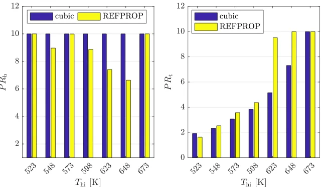
𝑇JC,B− 𝑇2?≥ 10 K Pressure ratio constraints 𝑃𝑅B ≤ 10
𝑇J,B− 𝑇2R≥ 10 K 𝑃𝑅D ≤ 10
Condensation pressure 𝑝A,B≥ 1 bar
constraints 𝑝A,D≥ 1 bar
3. Identification of optimal cascaded systems
The cascaded model can now be used to identify optimal working fluids and cycle operating conditions for cascaded systems intended for different heat-source temperatures. Since cascaded systems are more suited to higher-temperature applications, owing to the fact that high pressure ratios can be effectively divided across the topping and bottoming cycles, heat-source temperatures ranging between 250 and 400 °C will be considered. Moreover, since, from a thermodynamic perspective, the optimal cycle and working fluids are all independent of the heat-source heat-capacity rate, this is arbitrarily defied as 1 kW/K. The heat-sink is defined by 𝑇27 = 288 K, with heat-sink heat-capacity rate of 4.2 kW/K.
For each heat-source temperature, the optimisation procedure outlined in Section 2.3 is applied to identify the optimal working fluids and cycle operating conditions. The key results from the optimisation are summarised in Fig. 3. It is observed that the optimal critical temperature for both the bottoming and topping cycle increase with increasing heat-source temperature, and these relationships are linear. The topping requires a working fluid with a higher critical temperature than the bottoming cycle.
(a) (b)
[image:8.595.95.496.55.392.2](c) (d)
Fig. 3. Optimal cascaded ORC systems for different heat-source temperatures identified using the Peng-Robinson cascaded model. a) critical temperatures; b) net power output; c) pressure ratio; d) condensation temperature and evaporator pinch point.
The results shown in Fig. 3(d) are those for the bottoming-cycle condensation temperature, and the topping-cycle evaporator pinch point, which both increase as the heat-source temperature increases. The relatively high bottoming-cycle condensation temperatures are due to the heat-sink heat-capacity rate being fixed at 4.2 kW/K, and future studies should consider how this parameter affects the optimisation results in more detail. The saturation temperature difference, and the topping-cycle degree of superheat, were found to always remain on the respective lower bounds of 10 K and 5 K.
In summary, the results in Fig. 3 are helpful to identify the theoretically optimal working fluids and cycle conditions that result in the highest power output from a cascaded system. However, for these results to be applied to real-world applications it is necessary to map these optimal conditions to real working fluids. Referring to Fig. 3(a), there is a linear trend between heat-source temperature and the optimal critical temperatures. Therefore, working backwards, these results can be used to identify potential working fluids by finding existing fluids with similar critical temperatures. This is done by applying a linear regression to the results. The resulting correlations, and 𝑅- values, are shown for both the topping and bottoming
cycles in Fig. 3(a). Using these correlations, potential working fluids for each heat-source temperature have been identified (Tab. 3).
Table 3. Optimal working fluids for different heat-source temperatures identified using the results from the cascaded ORC optimisation using the Peng-Robinson equation of state.
𝑇H7 [K]
Bottoming cycle Topping cycle
Fluid name
𝑇23 [K] 𝑇23 [K]
Physical Theoretical Fluid name Physical Theoretical
523 R245ca 447.6 443.3 iso-hexane 497.7 495.2
548 R245ca 447.6 454.4 cyclo-pentane 511.7 512.0
573 iso-pentane 460.4 460.1 n-heptane 540.1 533.9
598 n-pentane 469.7 471.1 cyclo-hexane 553.6 551.3
623 n-pentane 469.7 473.1 n-octane 569.3 575.6
648 n-pentane 469.7 476.3 toluene 591.8 599.5
673 iso-hexane 497.7 481.4 pxylene 616.2 623.1
Fig. 4. Comparison between the power output produced from the theoretically optimal cascaded ORC systems identified using the Peng-Robinson model, and those obtained for a cascaded cycle optimised for real, predefined working fluids, using NIST REFPROP.
In terms of the net power output, the optimal cascaded systems operating with real working fluids have lower power outputs than the theoretically optimal systems. The reduction in the power output ranges between 4% and 11%, with the highest value being obtained for the highest heat-source temperature. Regarding the distribution of the power output, the optimisation considering real working fluids also results in the bottoming cycle producing the largest proportion of the power, and this again reduces as the heat-source temperature increases, as indicated by the right-hand plot in Fig. 4.
Fig. 5. Comparison between bottoming (left) and topping (right) pressure ratios of for the theoretically optimal cascaded ORC systems identified using the Peng-Robinson model, and those obtained for a cascaded cycle optimised for real, predefined working fluids, using NIST REFPROP.
4. Comparison to a simple ORC system
To conclude this paper, it is useful to compare the optimal cascaded systems identified in the previous section, to simple ORC systems designed for the same heat-source and heat-sink conditions. For this comparison, only systems operating with real working fluids are considered, and therefore the cascaded systems considered are the optimal systems identified when NIST REPFROP was used to calculate the fluid properties. The optimal simple ORC systems are identified by conducting a parametric investigation of different working fluids for each heat-source temperature, and in each case optimising the condensation temperature, reduced evaporation pressure, degree of superheat and evaporator pinch point to obtain the maximum power output. This optimisation is completed with variable bounds and constraints that are in-line with those described in Tabs. 1 and 2; the most notable of these is that the minimum pressure is constrained to be above atmospheric pressure.
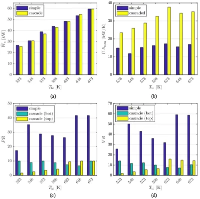
The simple and cascaded ORC systems are compared in Fig. 6, in terms of the power output, the heat-exchanger requirements, the system pressure ratio and the expander volume ratio. The heat-heat-exchanger requirements are evaluated by considering the product of the overall heat-transfer coefficient 𝑈, and the heat-exchanger area 𝐴, and this is easily evaluated based on the known heat-transfer rates and the log-mean temperature differences within each heat-transfer region (i.e., 𝑈𝐴 = 𝑄̇/𝛥𝑇qRr). The volume ratio is defined as the ratio of the expander inlet density to the expander outlet density (i.e., 𝜌I/𝜌J).
From Fig. 6(a) it is observed that both the simple and cascaded ORC systems generate a very similar power output. More specifically, for a 573 K heat source, the cascaded cycle generates 4% less power compared to the simple ORC. On the other hand, for the 648 K heat source the cascaded ORC system generates 2% more power than the simple ORC system. However, when evaluating the heat-exchanger and expander requirements, there is a clear difference between the two different systems. Due to the additional heat-exchange processes, the cascaded systems all have a much larger 𝑈𝐴 requirement, which is, on average, twice as large as a comparative simple ORC system. On the other hand, the system pressure ratio, and expander volume ratio, is significantly lower for the cascaded ORC systems, compared to the simple ORC system. Whilst this has advantages with regards to simplifying the expander design, and could also mean screw expanders could be considered as the expansion machine, it could be argued that a similar effect could be achieved by a simple ORC system operating with a two-stage turbo-expander, without a significant change in the power output.
alternative of a more sophisticated turbo-expander design. Alongside this, future studies should consider whether two-phase expansion could have a role in increasing the power output from a high-temperature cascaded ORC system, thus achieving better thermodynamic performance than a simple ORC system.
(a) (b)
(c) (d)
Fig. 6. Comparison between optimal simple and cascaded ORC systems for different heat-source temperatures. The optimisations compared are for cycles operating with existing working fluids, using NIST REFPROP to obtain fluid properties. a) power output; b) heat-exchanger requirements; c) pressure ratio; d) expansion volumetric ratio.
5. Conclusions
[image:11.595.95.496.116.514.2]than the power outputs identified as being the theoretical maximum. This demonstrates how the developed Peng-Robinson cascaded ORC model can be used as an effective tool during working-fluid selection. Finally, the optimal cascaded systems operating with real working fluids, are compared to equivalent simple ORC systems. Ultimately, from this preliminary comparison, it is observed that the power outputs from the two different systems are similar, but the cascaded system has on average twice the 𝑈𝐴
requirement than the simple system. The cascaded system also operates with lower system pressures ratios, and expander volume ratios, which means that volumetric expanders could be considered for the expansion stages. Future research should implement techno-economic optimisation and evaluate the potential of two-phase expansion within a cascaded system to further improve performance.
Acknowledgments
This work was supported by the UK Engineering and Physical Sciences Research Council (EPSRC) [grant number: EP/P009131/1].
Nomenclature
𝑎, 𝑏 Peng-Robinson parameters
𝐴, 𝐵, 𝐶 polynomial coefficients
𝑐6 specific-heat capacity at constant pressure, J/(kg K)
ℎ enthalpy, J/mol
𝑚̇ mass-flow rate, kg/s
𝑝 pressure, Pa
𝑝3 reduced pressure, 𝑝/𝑝23
𝑃𝑃H pinch point (start of evaporation in topping cycle), K
𝑃𝑅 pressure ratio
𝑞 vapour quality
𝑄̇H heat transfer rate, J/s
𝑅 universal gas constant, J/(mol K)
𝑠 entropy, J/(mol K)
𝑇 temperature, K
𝑈𝐴 product of overall heat-transfer coefficient and heat transfer area, J/(s K)
𝑉𝑅 volume ratio
𝑉& molar volume, m3/mol 𝑊̇ power, J/s
𝛼 Peng-Robinson parameter
𝜂 efficiency
𝜔 acentric factor
Δ𝑇FGD saturation temperature difference, K
Δ𝑇FH degree of superheat, K
Subscripts and superscripts b bottoming cycle bo boiling
c cold
ci, cp, co heat sink conditions (inlet, pinch and outlet) cr critical
e expander
h hot
hi, ho heat-source conditions (inlet, outlet) hp1, hp2 heat-source conditions (pinch 1, pinch 2)
n net
p pump
t topping cycle 1-4 orc state points ` saturation conditions
References
[1] Colonna, P., Casati, E., Trapp, C., Mathijssen, T., Larjola, J., Turunen-Saaresti, T., Uusitalo, A., Organic Rankine cycle power systems: From the concept to current technology, applications and an outlook to the future. J Eng Gas Turbines Power 2015;137(10):100801. doi: 10.1115/1.4029884.
[2] Vivian, J., Manente, G., Lazzaretto, A., A general framework to select working fluid and configuration of ORCs for low-to-medium temperature heat source. Applied Energy 2015;156:727-746.
[3] Maizza, V., Maizza, A., Working fluids in non-steady flows for waste energy recovery systems. Applied Thermal Engineering 1996;16(7):579-590.
[4] Read, M. G., Smith, I.K. & Stosic, N. Optimisation of power generation cycles using saturated liquid expansion to maximise heat recovery. P I Mech Eng E-J Pro 2017;231(1):57-69.
[5] Costall, A.W., Gonzalez Hernandez, A., Newton, P.J., Martinez-Botas, R.F., Design methodology for radial turbo expanders in mobile organic Rankine cycle applications. Applied Energy 2015;157:729-743. [6] Fischer, J., Comparison of trilateral cycles and organic Rankine cycles, Energy 2011;36:6208-6219. [7] Kane, M., Larrain, D., Favrat, D., Allani, Y., Small hybrid solar power system. Energy 2003;28:1427-1443.
[8] Kosmadakis, G., Manolakos, D., Kyritsis, S., Papadakis, G., Economic assessment of a two-stage solar organic Rankine cycle for reverse osmosis desalination. Renewable Energy 2009;34:1579-1586.
[9] Smith, I.K., Stosic, N., Mujic, E. and Kovacevic, A., Steam as the working fluid for power recovery from exhaust gases by means of screw expanders. P I Mech Eng E-J Pro 2011;225(2):117-125.
[10] Read, M.G., Smith, I.K., Stosic, N., Optimisation of power plant operating on waste heat of gas IC engine driven power generator. IMECE2016, 2016, 11-17th November, Phoenix, Arizonza, US.
[11] Badr, O., Probert, S.D., O’Callaghan, P.W., Selecting a working fluid for a Rankine-cycle engine. Applied Energy 1985;21:1-42.
[12] Chen, H.D., Goswami, Y., Stefanakos, E.K., A review of thermodynamic cycles and working fluids for the conversion of low-grade heat. Renewable and Sustainable Energy Reviews 2010;14(9):3059-3067. doi: 10.1016/j.rser.2010.07.006.
[13] Schilling, J., Lampe, M., Bardow, A., 1-stage CoMT-CAMD: An approach for integrated design of ORC process and working fluid using PC-SAFT. Chemical Engineering Science 2016;159:217–230. [14] White, M., Oyewunmi, O., Haslam, A., Markides, C, Industrial waste-heat recovery through integrated computer-aided working-fluid and ORC system optimisation using SAFT-γ Mie. Energy Conversion and Management 2017;150:851–869. doi: 10.1016/j.enconman.2017.03.048.
[15] Cignitti, S., Andreasen, J.G., Haglind, F., Woodley, J.M., Abildskov, J., Integrated working fluid- thermodynamic cycle design of organic Rankine cycle power systems for waste heat recovery. Applied Energy 2017;203:442–453. doi:10.1016/j.apenergy.2017.06.031.
[16] Poling, B.E., Prausnitz, J.M., O’Connell, J.P., The Properties of Gases and Liquids, 5th Ed.,
McGraw-Hill, New York, USA; 2001.
[17] Lemmon, E.W., Huber, M.L., McLinden, M.O., NIST Standard Reference Database 23: Reference Fluid Thermodynamic and Transport Properties-REFPROP. Version 9.1, National Institute of Standards and Technology, Standard Reference Data Program, Gaithersburg, USA; 2013.
[18] Brignoli, R., Brown, J.S., Organic Rankine cycle model for well-described and not-so-well-described working fluids. Energy 2015;86:93–104. doi: 10.1016/j.energy.2015.03.119.
[19] Luján, J.M., Serrano, J.R., Dolz, V., Sánchez, J., Model of the expansion process for R245fa in an organic Rankine cycle (ORC). Applied Thermal Engineering 2012;40:248-257.