REVIEW ARTICLE
Attosecond Single-Cycle Undulator Light: a Review
Alan Mak1, Georgii Shamuilov1,∗, Peter Sal´en1,2, David Dunning3,4, J´anos Hebling5, Yuichiro Kida6, Ryota Kinjo6, Brian W J McNeil3,7, Takashi Tanaka6, Neil Thompson3,4, Zolt´an Tibai5, Gy¨orgy T´oth5 and Vitaliy Goryashko1,∗
1FREIA Laboratory, Uppsala University, Uppsala, Sweden 2Stockholm University, Stockholm, Sweden
3Cockcroft Institute, Warrington, United Kingdom
4STFC Daresbury Laboratory, Warrington, United Kingdom 5University of P´ecs, P´ecs, Hungary
6RIKEN SPring-8 Centre, Hyogo, Japan
7SUPA University of Strathclyde, Glasgow, United Kingdom
∗corresponding authors
E-mail: [email protected]
E-mail: [email protected]
Abstract. Research at modern light sources continues to improve our knowledge of the natural world, from the subtle workings of life to matter under extreme conditions. Free-electron lasers, for instance, have enabled the characterization of biomolecular structures with sub-˚angstr¨om spatial resolution, and paved the way to controlling the molecular functions. On the other hand, attosecond temporal resolution is necessary to broaden our scope of the ultrafast world. Here we discuss attosecond pulse generation beyond present capabilities. Furthermore, we review three recently proposed methods of generating attosecond x-ray pulses. These novel methods exploit the coherent radiation of microbunched electrons in undulators and the tailoring of the emitted wavefronts. The computed pulse energy outperforms pre-existing technologies by three orders of magnitude. Specifically, our simulations of the proposed Soft X-Ray Laser (SXL) at MAX IV (Lund, Sweden) show that a pulse duration of 50-100 attoseconds and a pulse energy up to 5 microjoules is feasible with the novel methods. In addition, the methods feature pulse shape control, enable the incorporation of orbital angular momentum, and can be used in combination with modern compact free-electron laser setups.
Keywords: Free-electron lasers; Mode locking; Superradiance; Undulator radiation; UV and x-ray lasers; Ultrafast optics; Photoionization; Charge migration in molecules; Attosecond pump-probe capabilities.
PACS numbers: 41.60.Cr, 42.65.Re
1. Introduction
Ultrashort light pulses play an indispensable role in the progress of fundamental science, as they provide the necessary temporal resolution for probing and controlling ultrafast processes in matter. Short pulse durations offer a high temporal resolution, and the opportunity to enter a new scientific realm (see Sec. 2). The realms of
femtochemistry [1, 2] andfemtobiology[3] emerged when thefemtosecond (1 fs = 10−15s) time scale was enabled by mode locking in cavity lasers [4, 5]. Likewise, the realm of
attosecond science [6, 7] emerged when the attosecond (1 as = 10−18 s) time scale was reached by chirped-pulse amplification [8] and high-harmonic generation (HHG) [9]. Attosecond pulses have opened the possibilities to image [10] and control [11] the behaviour of electron wave packets within atoms. Further reduction to the zeptosecond
(1 zs = 10−21 s) pulse duration would enable the real-time observation of nucleonic
processes.
HHG is an established method of generating attosecond pulses, and a record pulse duration of 43 attoseconds was attained in October 2017 [12]. Retaining a sufficient photon flux becomes challenging when the pulse duration is reduced to the attosecond scale [13]. Moreover, the pulse-shortening capacity of HHG is trending towards exhaustion (see Sec. 2). These limitations call for a technological breakthrough. X-ray free-electron lasers (FELs) [14] are a promising new direction, as they offer a billion-fold improvement [15] in brilliance over previous x-ray sources. As of late 2018, the x-ray FEL facilities in operation are: FLASH [16] and European XFEL [17] in Germany; FERMI [18] in Italy; Swiss FEL [19] in Switzerland; LCLS [20] in the United States; SACLA [21] in Japan; and PAL XFEL [22] in South Korea. The MAX IV Laboratory in Sweden has also embarked on the design study of its Soft X-Ray Laser (SXL) facility [23].
X-ray FELs produce intense, coherent light using two main components: (i) a beam of relativistic electrons from an accelerator and (ii) a magnetic device known as the undulator (see Sec. 3). Existing x-ray FELs can readily deliver a pulse duration of 10-100 femtoseconds, and the production of sub-femtosecond pulses has been an active research area since the 2000s [24, 25, 26, 27, 28, 29, 30, 31]. A major obstacle to further reducing the pulse duration is that the number of optical cycles increases with every undulator period (elaborated in Sec. 5), so that an FEL pulse typically contains tens or hundreds of cycles.
In recent years, several novel concepts have been proposed to shift this paradigm, providing the theoretical basis for few-cycle [32], single-cycle [33, 34] and even half-cycle [35, 36] FEL pulses. In this article, we review three selected concepts, which feature waveform control in compact undulators (see Sec. 5.1), chirped microbunching (see Sec. 5.2) and FEL mode locking (see Sec. 5.3). The realization of these concepts is the objective of the LUSIA consortium (see Sec. 6).
In some of these concepts, it is possible to control the optical waveform in the pulse, and obtain a stable carrier-envelope phase (CEP). CEP stability is an important
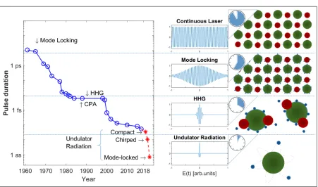
Figure 1. The plot on the left shows the minimum pulse duration attained over time, using data from Refs. [6, 13, 41]. The middle column depicts typical pulse shapes for each method of pulse generation. The right-hand column gives examples of systems whose dynamics can be analysed with these durations of pulses [7], such as (from top to bottom) phonon oscillations in solids, electron dynamics in solids, electron dynamics in molecules and electronic correlations in isolated atoms. Note that for HHG and undulator radiation, the central wavelength corresponds to the XUV and x-ray ranges.
property in attosecond science, as strong-field phenomena can be sensitive to the CEP [37, 38] and random CEP fluctuations from shot to shot can hinder the reproducible guiding of atomic processes [39].
The article concludes with an outlook on the development of this vibrant field of research (see Sec. 6). An example of future possibilities is the production of ultrashort light pulses carrying orbital angular momentum (OAM) [40].
2. Attosecond science and technology
2.1. Footsteps towards attosecond technology
The generation of ultrashort pulses has seen significant development during the last five decades, starting with the development of cavity mode locking in 1964 [4, 5]. Pulse durations have since been reduced by five orders of magnitude, as shown in Fig. 1.
With each instance of pulse duration reduction, new scientific realms emerged. For instance, femtochemistry [1, 2] and femtobiology [3] emerged when femtosecond pulses were made possible by mode locking in cavity lasers. With each advance, the demand for even shorter pulses increased.
The potential of pulse shortening by mode locking was fully exploited by the
Figure 2. The state-of-the-art of generating short pulses of light. The plot shows the pulse duration and pulse energy achievable by high-harmonic generation (empirical data [43, 44, 41]), existing free-electron lasers (empirical data [20, 21, 16, 45]), the Extreme Light Infrastructure (project targets [46]) and novel undulator-based concepts (simulations results [33, 34, 47]). The HHG and novel undulator concepts deliver few-cycle light pulses whereas the FEL sources shown in the figure deliver light pulses of more than a few cycles. An attosecond pulse of about 10µJ energy (e.g. “II” and “atto-LCLS”) is comparable to the blackbody radiation from a source at a temperature of 200 million kelvin, higher than the temperature of nuclear fusion. Furthermore, a focused intensity of 1022W/cm2 corresponds to the regime of ultra-relativistic optics [48].
1980s. However, the quest for shorter pulses stimulated the development of new methods such as high harmonic generation (HHG) in gas targets [42]. The invention of HHG was a prerequisite for breaking into the attosecond regime.
At present, HHG can deliver isolated pulses of less than 100 attoseconds, but as pointed out by Sansone et al. [13]: “the widespread adoption of attosecond sources has so far been limited ... due to the low photon flux characteristics of attosecond sources, particularly for producing isolated attosecond pulses.” Moreover, the potential of using HHG for further pulse shortening is expected to be exhausted by the late 2010s (see Fig. 1). Clearly, other methods of generating isolated short pulses must be investigated, in order to resolve the electron dynamics occurring at the time scale of only a few attoseconds.
The current state of the art of generating attosecond pulses is shown in Fig. 2, in terms of the pulse energy and duration. A few selected HHG sources are shown as blue asterisks. The capabilities of free-electron lasers in operation are shown as blue circles. The target parameters of the Extreme Light Infrastructure (ELI) [46] are shown as orange squares. The simulation results of the novel undulator concepts (elaborated in Sec. 5) are shown as red diamonds.
In August 2017, HHG sources have reached the carbon K-edge with a pulse duration of 53 attoseconds and a pulse energy of around 100 pJ [41]. However, Fig. 1 shows a clear
lack of significant progress in pulse shortening by HHG during the 2010s. Furthermore, from Fig. 2, the pulse energy dramatically decreases with the pulse duration: a reduction in pulse duration from 380 attosecond to 53 attosecond is accompanied by a four-order-of-magnitude decrease in pulse energy from 1.3µJ to 160 pJ. For comparison, the target parameters of the ELI source (phase 2) are 70 attoseconds at 10 nJ.
2.2. Attosecond science today
Attosecond light pulses enable the study of electronic motion in atoms, molecules and condensed matter on its natural time scale. HHG sources have permitted the initial exploration of such processes, addressing the delays in photo emission [49, 50], electron correlations [51, 11], valence electron motion [52] etc. and have enabled the imaging [10] and controlling [11] of electron wavepackets. HHG sources have also been applied to investigate charge migration [53] in molecules, a fast flow of electrons driven by the coherent superposition of electronic states, at a time scale down to
∼100 attoseconds [54]. Measurements of photoemission delays in solid matter with attosecond resolution have allowed a further understanding of electron transport through the surface [55] and the influence of different initial states on the emission time [56]. Moreover, attosecond methods have opened up the possibility to study the control of electronic currents with optical light fields [57, 58, 59, 60] – so-called lightwave electronics, which may enable a new electronics industry.
The development of laser technology and nanoengineering has laid the grounds for the recently emerging research area of attosecond physics at the nanoscale [61]. In traditional attosecond studies on atoms, molecules and extended solid materials, one typically assumes a spatially homogeneous laser field that interacts with the electrons. This is because the scale of the electron motion is small compared to the spot size of the intense ultrashort light pulses initiating the dynamics. However, the optical sub-wavelength confinement of the enhanced near-fields created by light-nanostructure interaction [62] enables a new regime of strong-field physics where the inhomogeneity of the electric field is a factor. The design of metallic or dielectric nanostructures, such as spheres, nanotips or antennas, as well as the choice of different materials, permits control of these inhomogeneous fields formed at the vicinity of the structure, which are generated by laser-induced plasmonic oscillations in the nanostructure. The produced fields can be measured by ejecting electrons with an attosecond pulse and streaking them with the plasmonic field [63]. Simulations have demonstrated that the inhomogeneity of the field implies important modifications for strong-field phenomena such as HHG [64, 65, 66, 67] and above-threshold ionization [68, 69]. Moreover, intense experimental effort has been dedicated to the investigation of HHG in noble gases using the strong plasmonic fields enabled by nanostructures [70, 71]. Recently, HHG using the solid tip nanostructure itself as an emitter was observed [72], and this opens up new opportunities for realizing coherent extreme ultraviolet sources for attosecond near-field applications.
2.3. Attosecond science beyond present capabilities
A real breakthrough in attosecond science demands the realization of attosecond-pump-attosecond-probe (APAP) experiments, which require pulse energies above 10 nJ [73]. Furthermore, there is a demand for even shorter pulses than presently available, of only a few attoseconds duration.
APAP experiments are necessary for obtaining the corresponding impact that femtosecond pulses has had on, e.g., femtochemistry. Intense femtosecond pulses are required to resolve atomic motions via pump-probe methods. Likewise, strong attosecond pulses are required to fully explore the new field of attochemistry, where electron motions and their influence on chemical reactions are investigated. For example, APAP methods could be applied to studies of charge migration, which is a fundamental process in biology [53]. As shown theoretically [74] this phenomenon is triggered by sudden ionization of biologically relevant molecules with XUV pulses. This leads to a charge flow from one part of the molecule to another, which is driven by electron correlation. Although such charge migration has been observed in amino acids, it is experimentally challenging and could only be probed indirectly by measuring the ions produced as a result of the charge flow [75] or by methods requiring aligned and oriented molecules, i.e. linear and polar molecules [54]. APAP techniques could enable charge migration to be directly followed on a proper time scale. For example, it could allow the charge flow induced at one molecular site by an attosecond XUV pulse to be monitored at another part of the molecule using an attosecond soft x-ray pulse combined with a spatially sensitive spectroscopic technique [76]. Few-attosecond pulses may furthermore allow the initial dynamics of charge migration, developing on the first tens of attoseconds [77, 78], to be investigated, and enable more exact comparison to simulations carried out with short time steps [77, 78].
Multidimensional attosecond x-ray spectroscopy has been proposed as an efficient nonlinear tool [79, 80] which can be fully exploited by development of more intense and shorter attosecond pulses. In this technique the molecular response to a sequence of variably delayed intense ultrashort x-ray pulses is measured. The recorded data can be visualized by multidimensional spectra that provide extra information compared with traditional nonlinear 1-dimensional methods, such as pump-probe spectroscopy. It allows the investigation of core-electronic couplings, as well as correlations and quantum coherences of valence electrons and holes in detail and could thus be complementary to APAP measurements of electron flow.
Electron correlations play an integral part in many processes initiated by XUV or x-ray pulses [81] and can be explored through the attosecond dynamics of atomic photoionization processes. APAP experiments have been suggested as an efficient tool to study the ultrafast auto-ionization dynamics of Fano resonances, a fundamental process where a bound and a continuum state are simultaneously excited and their mutual interaction leads to a decay of the bound into the continuum state [82]. By probing the ultrafast evolution of the Fano profiles via time-dependent photoelectron spectra,
the involved electron correlations can be investigated. Such studies will be essential for understanding and controlling multi-electron dynamics.
Further advances towards the control of electronic processes in atoms and molecules would benefit from detailed studies of the photoionization process using light pulses as short as a few attoseconds. For example, the interaction between the photoelectron created by extremely short pulses and the parent ion results in a mixing of different ionization channels, so-called interchannel coupling, that affects the coherence of the generated hole wavepacket in the parent ion. It has been suggested that this interchannel coupling may be relevant for understanding the hole dynamics of the HHG process [83] as well as charge transfer processes. In a theoretical study [84] the coherence properties of the hole wavepacket formed by photoionization of xenon using XUV pulses of 5-60 attoseconds has been investigated. It demonstrates a significant influence from the interchannel coupling on the formed wavepacket and predicts the dependency of the coherence on the ionizing pulse properties. Further experimental investigation of these effects and ultimately control of coherence requires widely tunable few-attosecond sources.
In the solid state, few-attosecond light pulses are desired for studies of graphene. Using 10-attosecond laser pulses the response of graphene to excitation can be investigated in real time [85]. Such studies will shed some light on its dynamical conducting properties, and could help increase the conversion efficiencies of solar cells. Moreover, the availability of intense attosecond soft x-ray pulses would open up opportunities for the APAP studies of, e.g., condensed-phase hole migration [86] and the sub-femtosecond dynamics of charge transfer processes on surfaces [87, 88].
Looking further forward to the shortest of FEL wavelengths presently thought feasible (∼0.1 ˚A) imaging and control of electronic-nuclear interactions such as nuclear excitation by electron transition or capture may become possible [89], which is relevant for nuclear batteries.
Temporal characterization of pulses shorter than presently available is an envisioned challenge for metrology. Today, the main technique in use is attosecond streaking [90]. The short pulse hits the gas target and causes photoemission of electrons. Thus, the light waveform is converted into a replicating electron wavepacket by single-photon absorption. These electrons are exposed to an additional streaking electric field (typically, in a linear region of an optical pulse). The photoelectrons’ interaction with this field affects their spectrum, namely, sidebands appear and peaks are shifted. Comparing it to non-streaked spectra allows one to reconstruct the duration and chirp of the ultrashort pulse. This requires phase retrieval methods, such as FROG-CRAB (frequency-resolved optical gating for complete reconstruction of attosecond bursts) [91]. The SPIDER method (spectral phase interferometry for direct electric-field reconstruction) can be used as well [92, 93]. Further details can be found, for instance, in Ref. [94].
However, there are significant limitations. As the pulse duration decreases to the few-attosecond or sub-attosecond regime, the streaking efficiency decreases. If one uses
S S S S S S S S S S
N N N N N N N N N N N
𝑧 𝑥 𝑦
𝜆
𝑢𝜆
𝜆
(b) Incoherent radiation (c) Coherent radiation
Undulator (a)
[image:8.612.127.466.83.310.2]S N S N S N S N S N S N S N S N S N S N S
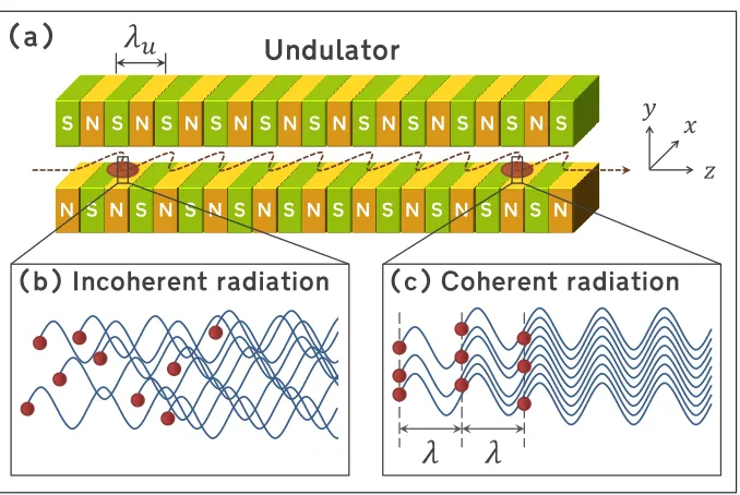
Figure 3. Working principle of a free-electron laser. (a) The electron bunch oscillates transversely and radiate, as it propagates down the undulator. (b) In the initial section of the undulator, the electrons are randomly phased within the bunch, and the radiation is largely incoherent. (c) In the subsequent section of the undulator, the electrons arrange themselves into sub-wavelength thin slices and this leads to coherent radiation. Figure adapted from Ref. [97].
a higher intensity of the streaking pulse, critical distortions in the spectrum will appear due to multi-photon absorption. FROG-CRAB starts with an assumption that the bandwidth of the short pulse is much smaller than the central energy of photoelectrons, a condition that cannot be met for sub-attosecond pulses. Chiniet al. proposed a different algorithm for the same experimental setup – phase retrieval by omega oscillation filtering (PROOF) [95]. It imposes no bandwidth limitations and can be used for ultrabroadband pulses down to the zeptosecond regime. Another promising approach suggested by Ipp
et al. is to use an intense counter-propagating pulse [96]. Its interaction with the short pulse would create electron-positron pairs in vacuum, which are exposed to the streaking pulse. The resulting time resolution in this case also belongs to the zeptosecond regime.
3. Free-electron laser principle
The free-electron laser (FEL) offers the prospects of producing intense attosecond x-ray pulses, thanks to its superb brilliance amongst laboratory x-ray sources [15] and the recently proposed concepts for pulse shortening (see Sec. 5).
A major difference between FELs and conventional lasers is the gain medium. For conventional lasers, the gain medium is a gas, liquid, crystal or semiconductor, wherein electrons are bound to atoms or molecules. For FELs, the gain medium is a beam of free electrons travelling through an undulator [see Fig. 3(a)]. These electrons are free
in the sense that they are not bound to atoms or molecules.
The undulator contains an array of dipole magnets with alternating polarity along its length. This results in a magnetic field that is temporally static and spatially periodic. Using the coordinate system in Fig. 3(a), the magnetic field is parallel to the y axis, and is periodic along the z axis. Theundulator period λu is typically in the order of a
few centimetres. The dimensionless undulator parameter K is typically in the order of unity and is defined as
K= eλuB0 2πmec
, (1)
where e is the absolute value of the electron charge, me is the electron mass, c is the
speed of light, and B0 is the amplitude of the periodic magnetic field.
The electron beam contains bunches of relativistic electrons delivered by a particle accelerator. The duration of each bunch is typically on the scale of 10–100 femtoseconds. As an electron travels along thez axis, it is deflected repeatedly by the periodic magnetic field, and hence oscillates in the x direction. These oscillations cause the electron to radiate at the resonant wavelength λ. On the z axis in the lab frame, this wavelength is given by
λ= λu 2γ2 1 +
K2
2 !
, (2)
where γ is the Lorentz factor, i.e. the electron energy normalized to the rest energy mec2.
As a side note, Eq. (2) accounts for two relativistic phenomena: (i) Lorentz contraction of the undulator period when observed in the electron rest frame; (ii) Doppler shift of the wavelength radiated by an electron when observed in the lab frame. The factor (1 +K2/2) arises from the average velocity of the electron rest frame with
respect to the lab frame [15].
Initially, the electrons are randomly distributed within the bunch, and the optical waves emitted by individual electrons have random relative phases. This process is known as spontaneous emission, and is depicted by Fig. 3(b). The resultant radiation is largely incoherent, as in a synchrotron light source.
However, the undulator of an FEL is typically much longer than that in a synchrotron. As the electrons continue along the z axis, they can interact collectively with the co-propagating radiation, such that the radiation is significantly amplified.
During the interaction, the electrons in the bunch gradually organize themselves into a series of thin slices along the z axis, as depicted by Fig. 3(c). These thin slices, called microbunches (or nanobunches), are equally spaced at the resonant wavelength λ. The thickness of each slice is small compared to λ.
With the formation of microbunches, the optical waves emitted by individual electrons become correlated in phase, and interfere constructively. The resultant radiation is largely coherent, as in a conventional laser. The radiation power grows exponentially during the interaction, and saturates when the microbunches are fully developed. The number of radiated wavefronts increases with the number of undulator
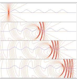
Figure 4. Evolution of the optical field emitted by a single electron propagating along a planar undulator. Each snapshot shows the scenario in thex-z plane, with the blue curve being the electron trajectory, and the red curves being the electric field lines. The snapshots are taken from the simulation tool developed by T. Shintake [98].
periods, as the wavefronts slip ahead of the electrons (see Fig. 4). Microbunching is an essential part of the FEL principle, and is crucial for the concepts discussed in Sec. 5.
When the spontaneous emission in the initial section of the undulator is amplified in the subsequent section, the mechanism is known as self-amplified spontaneous emission
(SASE) [99]. Alternatively, when an external laser is used in place of the spontaneous emission as the seed radiation to be amplified, the FEL is said to beseeded.
The undulator shown in Fig. 3(a) is a planar undulator, as the trajectory of the electron beam is confined within the x-z plane. In a helical undulator, however, the trajectory is a helix. While the radiation produced in a planar undulator is
linearly polarized, that produced in a helical undulator iselliptically polarized. Helical undulators also have the potential to produce light which carries orbital angular momentum [40].
4. Emitted field from undulator
Consider a short bunch (or a microbunch) of electrons passing through an undulator. To compute the electric field emitted by the bunch, we first invoke Feynman’s
formula [100] for the field radiated by a single moving charge q:
~ E = q
c2
∂2~e(t0)
∂t2 . (3)
Note that CGS units are used in this section. Here~eis the unit vector pointing from the charge to the observation point, and is evaluated at the retarded time t0. The retarded time is given by t0 =t−r(t0)/c, where r(t0) is the distance between the position of the charge at timet0 and the observation point. This means the field emitted by the charge at time t0 is detected at the observation point at time t. For simplicity, we restrict the analysis to the on-axisfield, and refer to Ref. [101] for a more general case.
In an ideal planar undulator, as depicted by Fig. 3(a), the magnetic field B~(z) is directed solely in the y dimension, and the electron motion is dominated by the oscillations in thexdimension. As a result, the radiated electric fieldE~(t) is dominated by its x component, and we may assume E =Ex.
The resultant field emitted by the bunch is the superposition of the fields emitted by individual electrons [given by Eq. (3)]. For a Gaussian distribution of electrons in the plane orthogonal to the direction of propagation, thetotal emitted field becomes
E = Qb c2S b
Z 2π
0
Z ∞
0
ρ exp − ρ
2
2σ2 b
!
∂2ex(t0)
∂t2 dρ dφ, (4)
whereρandφare the polar coordinates,Qb is the bunch charge,σb is the rms transverse
radius of the bunch, and Sb = 2πσb2 is the cross-sectional area of the bunch.
In the vicinity of the bunch such that the interaction length and distance from the bunch to the observation point are much smaller than the Rayleigh length, the integrals in Eq. (4) are computed in Feynman [100]. This results in
Enear=
2πQb
cSb
vx[t−∆z(t0)/c]. (5)
Here, vx is thexcomponent of the electron velocity and the retarded argument becomes
[t−∆z(t0)/c] with ∆z(t0) being the distance between the bunch and observation point. We will refer to this field as the near field. It is convenient to use z as an independent variable and rewrite the velocity term as
vx[t−∆z(t0)/c] =c
∂t0 ∂t dx dz retarded= c vz −1
−1 dx
dz
retarded. (6) To proceed with computing the emitted field, we first analyse the bunch trajectory in the undulator. Let A~(z) =A~x(z) be the vector potential normalized to its maximum
value, so that the undulator field B~(z) = B~y(z) equals the curl of the vector potential.
Invoking the Lorentz force law and Newton’s second law of motion, the transverse velocity of the bunch reads vx/c= (K/γ)Ax(z), and the longitudinal velocity reads
vz
c ≈1− 1 2γ2 −
1 2
v2 x
c2 = 1−
1 +K2A2 x(z)
2γ2 .
It follows from Eqs. (5) and (6) that the on-axis near field reads
Enear(s) =
4πQb
Sb
γKAx(s)
1 +K2A2 x(s)
, s≈ 2γ
2c
1 +K2A2 x
t− z
Here, sis the distance along the light pulse, which plays the role of the time coordinate. Also,A2
x is the average of A2x over the length Lu of the undulator, i.e.
A2 x =
1 Lu
Z Lu/2
−Lu/2
A2x(z) dz. (8)
For a multi-period undulator, Lu is simply the undulator period λu multiplied by the
number of undulator periods. For a single-period or non-periodic undulator, Lu can be
defined as the width of the autocorrelation function of the undulator field over the range of z wherein the undulator field is non-zero.
The far field is obtained as follows: (i) Fourier transforming Eq. (4) to the frequency domain; (ii) integrating over the transverse coordinates in the Fresnel approximation; and (iii) transforming back to the time domain. The result is
Efar = Qb
c2z
∂2x[t−∆z(t0)/c] ∂t2 .
Upon the change of variables using Eq. (6), the on-axis far field reduces to
Efar(z, s) =
2Qb
Sb
zR z
γKλuA0x(s)
[1 +K2A2 x(s)]
2. (9)
HereA0x = dAx/dsis the magnetic field, andzR =Sb/λis the Rayleigh length estimated
at the wavelengthλ =λu/2γ2.
Once the light pulse is emitted, its energy is conserved as it propagates. In other words, the pulse energy is independent of thezposition, so long as the position is outside the interaction region. We can therefore choose to compute the pulse energy from the near field (7), and obtain the result
Er ≈
πQ2bλu
Sb
K2
1 +K2A2 x
Z
A2x(s)ds. (10)
In Sec. 5, we shall use Eq. (10) to estimate the pulse energy attainable by the three undulator concepts for attosecond light.
Note that Eq. (10) applies to a short bunch, with thickness far less than the radiation wavelength λ. To treat a long bunch, we can divide the bunch into thin slices, so that the field emitted by each slice is given by Eqs. (7) and (9). The total field is then the superposition of the fields emitted by all slices. Similarly, one can account for energy spread.
5. Novel concepts
The standard FEL process (described in Sec. 3) is not favourable for producing attosecond light pulses, because of theslippage effect. As the electron beam propagates through an undulator and emits electromagnetic radiation, the radiation “slips” ahead of the electron beam by one wavelength per undulator period. The radiated wavefronts move ahead of the electron bunch because (i) a photon travels faster than an electron and (ii) the electron bunch takes a longer sinusoidal path than the optical pulse in the undulator [see Fig. 3(a)].
As the electrons radiate continuously and the radiated wavefronts move ahead of the electrons, the optical pulse is lengthened. At the exit of an undulator with Nu
periods the optical pulse contains Nu oscillation cycles [see Fig. 4]. This effect is an
obstacle to attaining attosecond pulse duration in existing FEL facilities. The standard FEL process by its nature produces radiation pulses, whose minimum duration is limited to the cooperation time (interchangeably referred to as the cooperation length).
The slippage allows the electrons in different parts of the beam to cooperatively interact via the common radiation field, resulting in the collective emission of coherent radiation with an exponential growth in radiation intensity. The cooperation length is the distance by which a radiation wavefront slips over the electrons while the radiation power is being amplified by a factor of e≈2.718. If the electron bunch is made shorter than the cooperation length or has a similar short region which is pre-prepared to lase preferentially, then the electromagnetic wave simply slips out ahead of the electrons before it can be fully amplified [102]. The minimum duration of such an amplified radiation pulse is thus fundamentally limited to the cooperation time – typically 200-300 attoseconds in the x-ray region.
The new fundamental physics behind the proposed concepts allows the breaking of this limit via optical slippage control in three different ways: (i) maximize emission with slippage limited to only one cycle, Sec. 5.1; (ii) taper the slippage to allow for constructive interference into an isolated single-cycle pulse, Sec. 5.2; (iii) discretize the slippage to support multiple few-cycle pulses, Sec. 5.3. These concepts apply optical methods to generate few- and single-cycle radiation pulses [33, 103, 101, 34, 35, 36, 47, 32], rather than e.g. limiting the size of the source electron bunch. In this way, the cooperation length plays no significant role in limiting pulse durations. This fundamental difference in approach potentially allows the generation of x-ray pulses up to three orders of magnitude shorter, i.e. of 300-zeptosecond duration, than methods using e.g. electron bunch shortening.
5.1. Waveform control by compact undulators
The concept proposed by Tibai et al. [33] is illustrated schematically in Fig. 5, and is elaborated analytically in Ref. [101]. It enables the production of single-cycle light pulses with a controlled waveform, and hence a stable carrier-envelope phase (CEP).
The scheme in Fig. 5 resembles that of high-gain harmonic genera-tion (HGHG) [104], in the sense that both consist of two undulators: a modulator and a radiator. However, the two schemes differ in the principle of emission. The HGHG radiator contains multiple undulator periods, and the light emitted by an electron mi-crobunch causes feedback onto the electron beam. After one undulator period, the emitted light slips ahead of the source microbunch by a distance λ. If at this position there is another microbunch and they are still within the undulator, the feedback loop takes place.
In contrast, the scheme in Fig. 5 has a short radiator, and there is no such feedback
⨂ 𝑧 𝑥 𝑦
𝐸𝑥
𝐵𝑦 𝐵𝑦
𝑧
𝑡
𝑒− beam
Modulation laser
𝜆𝐿
Train of such light pulses
𝜆
Modulator
undulator undulatorRadiator 𝒦
𝑧
𝛾
[image:14.612.136.455.87.250.2]Waveform resemblance
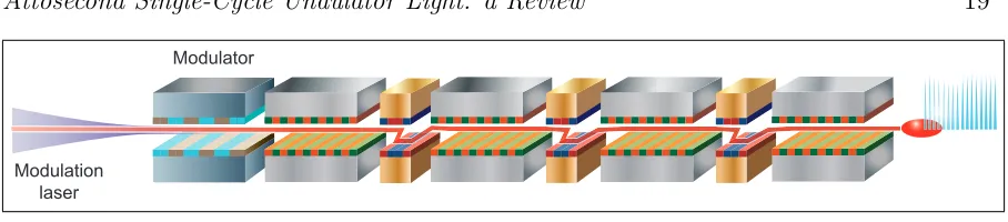
Figure 5. The scheme proposed by Tibai et al. [33] utilizes two compact undulators: amodulator and aradiator. In the modulator, an electron beam co-propagates with an external laser beam of wavelengthλL, thus creating an energy modulation of periodλL
along the electron beam. In the subsequent drift section, the energy modulation turns into a density modulation, and electron microbunches of thickness far less thanλLare
formed at intervals ofλL. In the radiator, each microbunch emits a single-cycle light
pulse, resulting in a train of single-cycle pulses at wavelengthλ. As shown analytically in Ref. [101], the electric waveform Ex of each light pulse reproduces the magnetic
waveformByof the radiator, and the former can be controlled directly by tailoring the
latter. This direct control leads to CEP stability.
mechanism. The essence of the scheme is thecoherent undulator radiation by an electron microbunch, discussed in Secs. 3 and 4. While HGHG relies oninter-microbunch phase correlation, this scheme relies on intra-microbunch phase correlation. To this end, the thickness of the microbunch must be far less than the wavelengthλgiven by the radiator resonance condition [Eq. (2)].
Let us consider the scheme step by step. A relativistic electron beam is sent through the modulator, wherein it co-propagates with a modulation laser beam. This process imparts a periodic energy modulation to the electrons. Downstream in the drift space, the energy modulation is converted into a density modulation, thus forming microbunches of high peak electric current. For negligible Coulomb repulsion, the thickness of the microbunch is proportional to the modulation period divided by the ratio of the energy modulation ∆γ to the beam energy spread σγ [105, 106], i.e.
λL/(∆γ/σγ). The numerical simulations [33] with the beam parameters of the FLASH
facility [16] show the feasibility of forming microbunches shorter than 10 nm even with strong Coulomb repulsion. A 10-TW, 800-nm modulation laser imparts a strong energy modulation (∆γ/σγ ≈ 200), which overcomes the Coulomb repulsion and results in up
to a 100-fold increase in the peak current. The bunch length turns out to be twice of the theoretical value for negligible Coulomb repulsion.
After the drift section, the microbunched electron beam emits coherent light in the radiator, which has a tailored magnetic field pattern (see Fig. 6). The temporal waveform of the emitted pulseEx(s) resembles the spatial pattern of the magnetic field 4
Figure 6. Simulation results showing the magnetic field of the radiator (blue) and the electric field of the emitted attosecond pulse (red). Reprinted figure with permission from [33] c2014 by the American Physical Society.
By(s) in the radiator. Here, s stands both for the coordinate along the radiation pulse
and coordinate along the undulator field. In particular, for K < 1, the emitted field Ex(s) is directly proportional toBy(s/γ2), which is the derivative of the undulator vector
potential [see Eq. (9)]. For GeV electron beams and few-centimetre-long undulators, this implies the generation of attosecond light pulses. Thus, manipulating the magnetic field pattern of the radiator allows full control over the number of cycles (hence the duration) and the precise waveform (hence the CEP) of the light pulse [107].
For the radiator in Fig. 5, the normalized vector potential can be written as
Ax =
z σu
exp − z
2
2σ2 u
!
(11)
for some characteristic lengthσu. The emitted pulse energy (10) then reduces to
Er ≈
πQ2 bσu
Sb
√
πK2/2
1 +√πK2/2. (12)
The maximum Er is obtained when K 1. However, the field profile Ex(t) becomes
strongly distorted when K > 2. A good compromise is to have K ∈ (1,2), such that
Er ≈ 2σuQ2b/Sb. For a long Gaussian bunch of duration σT and for K < 1/2, the
expression for the total emitted energy is similar to Eq. (12), but is modified by a factor of (1 +σT2/σt2)−3/2. Here, σt = (λu/2cγ2)(1 +K2A2x) is the characteristic period of the
waveform emitted by a thin slice [see Eqs. (7) and (9)].
Following the parameters of the simulation example in Ref. [33], undulator length scaleσuis 14 cm (one half of the period), microbunch chargeQbis 1.2 pC, transverse size
σb is 70µm and undulator parameter K is 0.5. The modulation laser operates at power
10 TW and wavelength 800 nm. As a result, quasi-half-cycle light pulses are generated
at the central wavelength of λ = 20 nm, with a pulse duration of 80 attoseconds and pulse energy of 27 nJ.
Besides the pulse energy, the stability of the waveform is crucial for attosecond field-driven experiments. For attosecond light pulses with the parameters discussed above, the standard deviation of the CEP is 31 mrad in the case of a perfectly CEP-stable modulating laser, and 300 mrad in the case of a modulating laser with a random CEP [108].
If a multicycle modulation laser is used, the electron beam consists of microbunches separated by the wavelength of the modulation laser. Hence, a train of attosecond pulses is generated. An approach to produce isolated attosecond pulses is to use two modulation lasers with significantly different wavelengths [106]. Another approach is to shorten the number of cycles of the modulation laser to only two or less [108].
5.2. Chirped microbunching in tapered undulator
To enhance the intensity of single-cycle light pulses from undulators, a second concept was proposed by Tanaka [34]. The concept exploits the slippage effect to its advantage, and is shown schematically in Fig. 7. A key element of the scheme is chirped microbunching, whereby the electron microbunches are spaced at varying intervals, instead of being equidistant to each other as in the standard FEL process. These microbunches pass through a tapered undulator, whose magnetic field amplitude (and hence K) varies slowly along the longitudinal axis.
There are three conditions to be satisfied. First, the number of microbunches should be similar to that of the undulator periods. Second, the nth spacing between the microbunches, λn, should equal the slippage length at thenth period of the tapered
undulator. Third, the variation of λn should be large and rapid enough. Once these
conditions are satisfied, intense single-cycle light pulses can be generated.
The principle of the scheme is illustrated in Fig. 8. We consider a total of 10 microbunches, with a current profile as shown in panel (a). Here, s denotes the longitudinal coordinate, along which the microbunches are spaced at decreasing intervals λ1, λ2, ..., λ10. These microbunches are made to travel through a 10-period tapered
undulator, which satisfies the three aforementioned conditions.
Figure 8(b) shows the temporal profile of the emitted electric field immediately after the 1st undulator period. The waveform comprises 10 optical cycles, and reflects the current profile of the microbunches. However, the entire waveform is shifted forward in s by a distance of λ1, due to the slippage. We refer to the optical cycle located at s=λ1 (indicated by the yellow arrow) as the resonant pulse.
Figure 8(c) shows the electric field profile immediately after the 2nd undulator period. The blue dotted line represents the waveform emittedwithin the 2nd undulator period. The red solid line represents the previously generated waveform, which is shifted forward in s due to the slippage. As the slippage length at the 2nd undulator period is λ2, the resonant pulse is now located at s=λ1+λ2 instead ofs= 2λ1. Considering the 4
Figure 7. The Tanaka scheme [34] utilizes chirped microbunching, whereby the electron microbunches are spaced at varying intervals. An intense single-cycle light pulse is generated as the microbunches pass through a properly tapered undulator.
Figure 8. Mechanism to generate a single-cycle light pulse by means of chirped microbunching in a tapered undulator. The figure adopted with permission from [34]
c
2015 by the American Physical Society.
[image:17.612.144.444.420.710.2]superposition of the two waveforms, it is apparent that the interference isconstructiveat the position of the resonant pulse (indicated by the yellow arrow), but is not necessarily so at other positions. The same argument applies to the 3rd (d) and 4th (e) undulator periods, where the waveforms generated at respective periods are indicated by the green and cyan lines, respectively.
The red solid lines in Fig. 8(f) show the waveforms after the 10th undulator period. The interference at the resonant pulse is totally constructive, while those at other positions are rather destructive. Summing up all the waveforms, an intense single-cycle pulse is generated at the resonant pulse, as indicated by the red dashed line. Since the resultant electric field strength is proportional to the number of microbunches Nb,
the emitted energy scales as Nb2. Typically, Nb 1. Using Eq. (10), the maximum
emitted energy is estimated to be
Er ≈
Nb2Q2bλu
Sb
. (13)
To account for the effect of a finite electron bunch duration, for a long undulator Eq. (13) has to be multiplied by the so-called bunch form-factor F2 = exp(−2π2σT2/σt2).
The illustration in Fig. 8 makes use of waveforms of constant amplitudes, which is, however, not the case for a tapered undulator. Recall that the emitted field amplitude is proportional to K [see Eq. (9)]. Fortunately, the diffraction effect can help equalize the amplitude along the pulse. From Eq. (9), it follows that E ∝zR(s)K(s)∝ K(s)/λ(s).
Then, for a positive undulator taper K0(s) > 0, an increase in K can partly be compensated for by a decrease in the Rayleigh length zR [36].
Despite the simplicity in the operation principle, the implementation of the scheme is not altogether straightforward. In practice, the original scheme in Ref. [34] requires many hardware components, such as two modulators and three magnetic chicanes. Furthermore, the performance of the scheme is extremely sensitive to the energy spread of the electron beam. This sensitivity comes from the difficulty to prepare the chirped sinusoidal microbunched beam. This cannot be directly done only by the single-cycle seed laser, no matter how strong its peak power is. Thus, an intermediate step is required to generate a chirped radiation pulse for modulation.
To overcome such difficulty, a more efficient scheme has been proposed in Ref. [35], in which the microbunch train consists of narrow peaks withvarying separations around λL. Such a train can be directly generated by an intense single-cycle seed laser, and so
the accelerator layout can be significantly simplified. More importantly, the requirement on the energy spread of the electron beam is greatly relaxed, because the intermediate step is no longer necessary. In addition, the radiation spectrum can be much broader than what is available in the original scheme, thus opening up the possibility to reach a much shorter pulse duration.
Modulator
[image:19.612.71.525.70.170.2]Modulation laser
Figure 9.Schematic diagram of a mode-locked FEL system showing an electron beam energy modulator and a series of undulator-chicane modules. Reprinted figure with permission from [47] c2008 by the American Physical Society.
5.3. Mode-locked free-electron laser
In conventional cavity lasers [109] the boundary conditions imposed by the cavity and the repetitive interference of the light within the cavity ensure that only those radiation wavelengths which are an integer fraction of the cavity length, i.e. the modes, can survive many round trips within the cavity.
In a ring cavity of length lcav, the mode spacing in the frequency space is ∆ωcav =
2πc/lcav. If the amplification of a mode is modulated, then it develops sidebands at the
modulation frequency. When this modulation frequency equals the mode spacing, the sidebands overlap with adjacent modes, thus coupling and locking their relative modal phases. In the temporal domain, such a mode-locked frequency spectrum corresponds to a train of well-defined short pulses with pulse-to-pulse separation of lcav/c.
Thompson and McNeil [47] proposed to apply the same principle of mode locking to an FELamplifier. By introducing magnetic chicanes between the undulator modules, as shown in Fig. 9, a periodic delay can be imposed on the electron bunch so that the wavefronts emitted from each undulator module are delayed and overlapped, enabling interference to occur.
This enhanced, periodic slippage process of a light waveform relative to the electron beam of total distance s in each undulator-chicane module, is analogous to that which would occur in a conventional ring cavity of length s, allowing modes to develop with a mode spacing frequency of ∆ω = 2πc/s. Furthermore, if, as in the conventional cavity laser, the FEL amplification process is modulated at the mode spacing, e.g. by modulating the electron beam energy [47] or current [110], the modes may lock and generate a train of short pulses. With LCLS-like parameters and a radiation wavelength of 1.5 ˚A, an rms pulse duration of ∼ 18 attoseconds (corresponding to ∼ 50 optical cycles) is predicted.
The method of Ref. [47] has been adapted in Ref. [32] to reduce the rms pulse duration down to ∼ 700 zeptoseconds, corresponding to only a few oscillation cycles, and to allow an easier implementation of the method on existing FELs. A schematic of the method is shown in Fig. 10.
First, the electron beam properties are modulated to impose longitudinally varying beam quality for FEL lasing. One method is to modulate the electron beam energy, using an external laser and a short modulator undulator (alternatives e.g. current
Slicing P Amplifier Stage Mode-Locked Afterburner
0 0 0
P P
γ γ
γ
γ0 γ0 γ0
(a)
s s s
z
Amplifier Afterburner
z (b)
Log(b) Log(P) s
s
Min Max
λm
λr
[image:20.612.76.526.67.243.2]λm
Figure 10. Schematic diagram of the mode-locked afterburner FEL concept. The electron beam is sliced (e.g. using an external laser and a short modulator to apply an energy modulation around the central Lorentz factor,γ0). During normal exponential FEL amplification (amplifier stage), a longitudinal comb structure develops in the FEL microbunching (e.g. peaked at the minima of the electron beam energy) but not in the radiation intensity (P). Further amplification of the radiation with periodic electron delays (mode-locked afterburner stage) generates a train of few-cycle radiation pulses. Reprinted figure with permission from [32] c2013 by the American Physical Society.
modulation may also be used). The modulation period is chosen to be ∼1-2 orders of magnitude greater than the resonant wavelength of the subsequent amplifier stage, giving multiple modulation periods per cooperation length. Given sufficient amplitude, the effect of such modulation is to separate the beam into regions of low/high energy gradient, corresponding to high/low quality for FEL amplification.
The modulated beam is injected into a conventional FEL amplifier, in which emitted radiation continuously slips forward relative to the electrons, i.e. no periodic delays. During this stage the slippage smooths any significant modulation from developing in the radiation, even while large longitudinal variation in microbunching develops due to varying electron beam quality. The case using energy modulation is nuanced by the fact that two regions of low energy gradient occur per modulation period, i.e. the energy maxima and minima (alternative modulation methods are simpler in this respect). The energy minima is favoured due to FEL gain asymmetry [32] and preferential direction of energy curvature about the extrema [111]. The increased FEL interaction around the beam energy minima therefore generates a handful of microbunches per modulation period.
Shortly before FEL saturation occurs, both the electron beam and the radiation are injected into the mode-locked afterburner. This uses the same principle as the original mode-locking method of Ref. [47] as described above, of using a series of undulator-chicane modules to amplify and lock a series of modes. The short undulator modules and chicanes are tuned to ensure the repeated gain and the shifting of the radiation pulses along the beam to the next region of strong microbunching. The number of the microbunches in each handful Nb is approximately adjusted to the number of periods
in the afterburner Nu, e.g. Nb ≈Nu =N. Then, using Eq. (10), the maximum emitted 4
20 40 60 80 100 120 140 0
0.5 1 1.5
t [as]
P [GW]
0.090 0.1 0.11 5
10 x 104
λ [nm]
P (
λ
[image:21.612.77.527.68.233.2]) [a.u.]
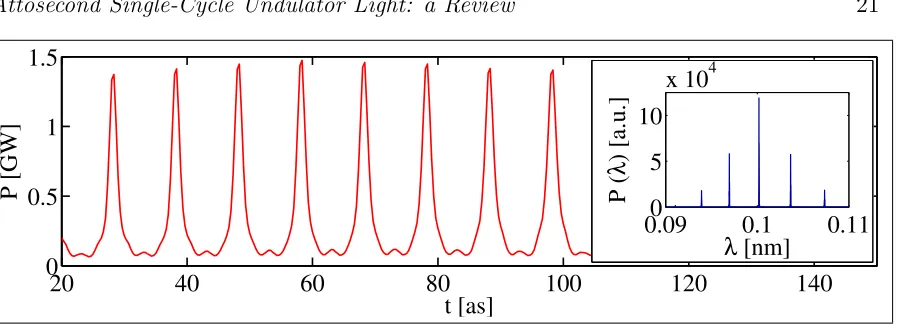
Figure 11. Three-dimension simulations of mode-locked afterburner using SACLA-like parameters. The main panel shows the pulse train in the temporal domain and the inset shows the modal structure in the wavelength domain. The individual pulses have an rms duration of∼700 zeptoseconds each, and are separated by∼10 attoseconds. Reprinted figure with permission from [32] c2013 by the American Physical Society.
energy in one pulse can be estimated as
Er ≈
N3Q2 bλu
Sb
. (14)
The number of periods Nu is kept small (around 5) to obtain sub-attosecond pulse
duration. Meanwhile, the enhancement is strong enough to deliver a pulse energy at the nJ scale.
An example of a mode-locked afterburner simulation output using parameters taken from Ref. [32] and similar to those of the SACLA FEL [21] is shown in Fig. 11. A pulse train structure of approximately 700 zeptosecond RMS duration radiation pulses separated by 10 attoseconds and of 1.5 GW peak power is generated. The multichromatic spectrum has a bandwidth envelope a factor ∼ 100 times that of the normal SASE output.
The mode-locked afterburner is potentially a relatively simple upgrade to existing x-ray FEL facilities and offers a flexible route towards the generation of few-cycle x-ray pulse trains with GW peak powers.
5.4. Features and potential of the concepts
We compare the three novel concepts by numerical simulations, using a set of electron parameters for the Soft X-Ray Laser (SXL) facility [23] at MAX IV (see Table 1). The parameters for the undulators and the modulation laser are tuned to deliver soft x-ray pulses with a duration of 50–100 attoseconds. Characteristics of the resulting pulse for each scheme are listed in Table 2.
In Table 1, γmec2 is the beam energy, σγ/γ the relative energy spread, γx,y the
normalized transverse emittance, σx,y the rms beam radius,σt the rms bunch duration,
Ipeak the peak current,λLthe central wavelength andεr is the laser pulse energy. Also,
Nmodule is the number of undulator modules, andLmodule the length of each module.
Table 1. Input Parameters for the Numerical Simulations
Compact Chirped Mode-locked
undulators bunching FEL
Parameter (see Sec. 5.1) (see Sec. 5.2) (see Sec. 5.3) Electron Beam Injected
γmec2 [GeV] 1.5 1.5 1.5
σγ/γ 5×10⁻⁴ 5×10⁻⁴ 5×10⁻⁴
γx,y [µm] 0.5 0.5 0.5
σx,y [µm] 30 16 30
σt [fs] 100 100 100
Ipeak [kA] 3 3 3
Modulation Laser
λL [nm] 516 800 100
εr [mJ] 85 5 0.01–0.1
First Undulator Section (Modulator)
Nmodule 1 1 1
Lmodule [m] 0.66 3 1.28
λu [mm] 660 100 128
K 5 14.0–17.4 5
Second Undulator Section (Radiator or Amplifier)
Nmodule 1 1 6
Lmodule [m] 0.49 3 2.25
λu [mm] 196 100 22.5
K 0.8 14.0–17.4 1.5
Third Undulator Section (Afterburner)
Nmodule N/A N/A 20
Lmodule [m] N/A N/A 0.18
λu [mm] N/A N/A 22.5
K N/A N/A 1.5
For concept 5.1, the undulator period λu should be understood as the characteristic
length σu defined in Eq. (11).
In Table 2, Nb is the number of microbunches, while Qb and σt are the charge
and duration of each microbunch. Also, Ncycle is the number of optical cycles, λ the characteristic wavelength (i.e. that with the highest spectral intensity), and ∆t the pulse duration (FWHM). For all the three concepts, the emitted pulse energy εr
from the analytical calculation is in reasonable agreement with that from the numerical simulation, and can be seen as a conservative estimate.
The scheme in Sec. 5.1 is simple, robust and capable of delivering both pulse trains and isolated pulses. Importantly, it also features direct pulse shape control and CEP stability by means of tailoring the magnetic field profile.
Table 2. Output Parameters for the Numerical Simulations
Compact Chirped Mode-locked
undulators bunching FEL
Parameter (see Sec. 5.1) (see Sec. 5.2) (see Sec. 5.3) Electron Microbunch Developed
Nb 1 30 10×20
Qb [pC] 1.3 3 0.03
σt [as] 8 63 4.5
Ipeak [kA] 57 20 6
Optical Pulse Emitted
Ncycle 1 1 5
λ [nm] 17 50 2.78
σλ/λ 0.2 0.5 0.17
∆t [as] 55 100 50
εr [nJ] 120 4700 375
Comparison with Analytical Estimate
Formula Eq. (12) Eq. (13) Eq. (14)
εr [nJ] 100 3600 250
The approach described in Sec. 5.2 is an endeavour to deliver the highest energy in an ultrabroadband pulse. Still, the undulator taper can be properly optimized for CEP stability. A related work presented in Ref. [36] analytically derives the condition for optimal undulator tapering and microbunch chirping. With it, a quasi-half-cycle light pulse can be generated.
For the proposal in Sec. 5.3, the selected electron beam parameters are rather conservative. This scheme reaches its best performance in the hard x-ray regime, with an unprecedented sub-attosecond pulse duration. For existing x-ray FELs, it is an attractive operation mode that can be pursued with a relatively simple upgrade. Further increase in pulse energy can be achieved by using isochronous chicanes [112], which better preserve the electron microbunches developed during the amplifier stage.
6. Summary and outlook
In this article, we have reviewed and compared three novel concepts for generating attosecond x-ray pulses. All these concepts utilize the core element of the FEL principle (Sec. 3), namely, the coherent radiation of microbunched electrons in undulators. Meanwhile, each concept is characterized by a unique feature: waveform control in compact undulators (Sec. 5.1), chirped microbunching (Sec. 5.2) and FEL mode locking (Sec. 5.3). In particular, waveform control also provides the basis for CEP stability.
These concepts are an important breakthrough for two main reasons. First, they have shown the potential to overcome the limitations of HHG, thus yielding a shorter
pulse duration and higher pulse energy. Taking advantage of the FEL principle, they enable an unprecedentedbrilliance amongst laboratory x-ray sources. Second, they shift the paradigm that FEL pulses must contain at least tens or hundreds of optical cycles, and they pave the way to obtaining single-cycle FEL pulses. This reduces the pulse duration from the femtosecond regime to the attosecond regime, making the FEL an ever more favourable tool for attosecond science (Sec. 2).
While each concept has its unique merits, it is natural to consider combining the strengths of the different concepts, to further enhance the performance of the attosecond x-ray sources. This is a subject of further study beyond this review article.
Another aspect of further development is the incorporation of orbital angular momentum (OAM) into the attosecond light pulses produced in undulators. Light carrying OAM (also called topological charge or vortex) has a spatial structure associated with a helically shaped wavefront [113] and provides an additional degree of freedom invaluable in the experiments. Possible applications of such light beams range from fundamental science [114, 115, 116, 117] to nearly industrial concepts, for instance, in telecommunications [118, 119]. Decreasing the pulse length down to several cycles would allow scientists to investigate ultrafast processes in combination with the unique properties of topological charge.
One more important point is the advancement in development of compact free-electron lasers based on plasma wake-field acceleration [120, 121, 122]. With the single-cycle concepts, such light sources can become an ultimate scientific tool with a size of a typical laboratory room. However, it remains challenging to optimize the parameters for its efficient operation, most importantly, the energy spread of the electron beam. Still, it is an important direction of future research.
The production of single-cycle light in undulators is a vibrant research area. To facilitate international and interdisciplinary collaboration in this area, the LUSIA consortium [123] was formed in 2017. The acronym LUSIA stands for Attosecond SIngle-cycle Undulator Light. The consortium comprises the pioneers of this research area in 6 countries (as of 2018): Sweden, Germany, Hungary, Japan, Ukraine and the United Kingdom. The ultimate objective is to deliver intense attosecond single-cycle CEP-stable x-ray pulses to the users of FEL beamlines. The new techniques developed by the consortium can potentially be applied to the design of the Soft X-Ray Laser (SXL) facility [23] at the Swedish national accelerator laboratory MAX IV.
Funding Information
The authors acknowledge the Swedish Research Council (VR, project 2016-04593), the Royal Swedish Academy of Sciences (KVA, project PH2018-0037) and the Stockholm-Uppsala Centre for Free-Electron Laser Research (SUFEL) for their support.
References
[1] A. H. Zewail. Laser femtochemistry. Science, 242(4886):1645–1653, dec 1988.
[2] Ahmed H. Zewail. Femtochemistry. past, present, and future. Pure and Applied Chemistry, 72(12), jan 2000.
[3] Villy Sundstr¨om. Femtobiology. Annual Rev. Phys. Chem., 59(1):53–77, may 2008. [4] Willis E. Lamb. Theory of an optical maser. Phys. Rev., 134(6A):A1429–A1450, jun 1964. [5] H.A. Haus. Mode-locking of lasers. IEEE Journal of Selected Topics in Quantum Electronics,
6(6):1173–1185, nov 2000.
[6] P. B. Corkum and Ferenc Krausz. Attosecond science. Nature Physics, 3(6):381–387, jun 2007. [7] Ferenc Krausz and Misha Ivanov. Attosecond physics. Rev. Mod. Phys., 81(1):163–234, feb 2009. [8] Donna Strickland and Gerard Mourou. Compression of amplified chirped optical pulses. Opt.
Comm., 56(3):219–221, dec 1985.
[9] Jeffrey L. Krause et al. High-order harmonic generation from atoms and ions in the high intensity regime. Phys. Rev. Lett., 68(24):3535–3538, jun 1992.
[10] D. M. Villeneuve et al. Coherent imaging of an attosecond electron wave packet. Science, 356(6343):1150–1153, jun 2017.
[11] Christian Ott et al. Reconstruction and control of a time-dependent two-electron wave packet. Nature, 516(7531):374–378, dec 2014.
[12] Thomas Gaumnitz et al. Streaking of 43-attosecond soft-x-ray pulses generated by a passively CEP-stable mid-infrared driver. Optics Express, 25(22):27506, oct 2017.
[13] Giuseppe Sansone, Luca Poletto, and Mauro Nisoli. High-energy attosecond light sources. Nature Photonics, 5(11):655–663, sep 2011.
[14] Zhirong Huang and Kwang-Je Kim. Review of x-ray free-electron laser theory. Physical Review Special Topics - Accelerators and Beams, 10(3), mar 2007.
[15] Brian W. J. McNeil and Neil R. Thompson. X-ray free-electron lasers. Nature Photonics, 4(12):814–821, nov 2010.
[16] Siegfried Schreiber and Bart Faatz. The free-electron laser FLASH. High Power Laser Science and Engineering, 3, 2015.
[17] E. Cartlidge. European XFEL to shine as brightest, fastest x-ray source. Science, 354(6308):22– 23, oct 2016.
[18] E. Allaria et al. The FERMI free-electron lasers. J. Synch. Rad., 22(3):485–491, apr 2015. [19] Christopher Milne et al. SwissFEL: The swiss x-ray free electron laser. Applied Sciences, 7(7):720,
jul 2017.
[20] P. Emma et al. First lasing and operation of an ˚angstrom-wavelength free-electron laser. Nature Photonics, 4(9):641–647, aug 2010.
[21] Tetsuya Ishikawa et al. A compact x-ray free-electron laser emitting in the sub-˚angstr¨om region. Nature Photonics, 6(8):540–544, jun 2012.
[22] In Ko et al. Construction and commissioning of PAL-XFEL facility. Applied Sciences, 7(6):479, may 2017.
[23] Sverker Werin et al. The Soft X-Ray Laser project at MAX IV. In Proceedings of the 8th International Particle Accelerator Conference, Copenhagen, Denmark, 2017, pages 2760–2762, Geneva, Switzerland, may 2017. JACoW.
[24] Alexander A. Zholents and William M. Fawley. Proposal for intense attosecond radiation from an x-ray free-electron laser. Phys. Rev. Lett., 92(22):224801, jun 2004.
[25] P. Emma et al. Femtosecond and subfemtosecond x-ray pulses from a self-amplified spontaneous-emission–based free-electron laser. Phys. Rev. Lett., 92(7):074801, feb 2004.
[26] E. L. Saldin, E. A. Schneidmiller, and M. V. Yurkov. Self-amplified spontaneous emission FEL with energy-chirped electron beam and its application for generation of attosecond x-ray pulses. Physical Review Special Topics - Accelerators and Beams, 9(5), may 2006.
[27] D. Xiang, Z. Huang, and G. Stupakov. Generation of intense attosecond x-ray pulses using
ultraviolet laser induced microbunching in electron beams. Phys. Rev. ST Accel. Beams, 12(6):060701, jun 2009.
[28] L. Giannessi et al. Self-amplified spontaneous emission free-electron laser with an energy-chirped electron beam and undulator tapering. Physical Review Letters, 106(14), apr 2011.
[29] Eduard Prat and Sven Reiche. Simple method to generate terawatt-attosecond x-ray free-electron-laser pulses. Phys. Rev. Lett., 114(24):244801, jun 2015.
[30] James D. Sadler et al. Compression of x-ray free electron laser pulses to attosecond duration. Scientific Reports, 5(1), nov 2015.
[31] Senlin Huang et al. Generation of subterawatt-attosecond pulses in a soft x-ray free-electron laser. Physical Review Accelerators and Beams, 19(8), aug 2016.
[32] D. J. Dunning, B. W. J. McNeil, and N. R. Thompson. Few-cycle pulse generation in an x-ray free-electron laser. Physical Review Letters, 110(10), mar 2013.
[33] Z. Tibai et al. Proposal for carrier-envelope-phase stable single-cycle attosecond pulse generation in the extreme-ultraviolet range. Physical Review Letters, 113(10), sep 2014.
[34] Takashi Tanaka. Proposal to generate an isolated monocycle x-ray pulse by counteracting the slippage effect in free-electron lasers. Physical Review Letters, 114(4), jan 2015.
[35] Yuichiro Kida, Ryota Kinjo, and Takashi Tanaka. Synthesizing high-order harmonics to generate a sub-cycle pulse in free-electron lasers. App. Phys. Lett., 109(15):151107, oct 2016.
[36] V. A. Goryashko. Quasi-half-cycle pulses of light from a tapered undulator. Physical Review Accelerators and Beams, 20(8), aug 2017.
[37] Liang-You Peng and Anthony F. Starace. Attosecond pulse carrier-envelope phase effects on ionized electron momentum and energy distributions. Physical Review A, 76(4), oct 2007. [38] Candong Liu et al. Carrier-envelope phase effects of a single attosecond pulse in two-color
photoionization. Physical Review Letters, 111(12), sep 2013.
[39] A. Baltuˇska et al. Attosecond control of electronic processes by intense light fields. Nature, 421(6923):611–615, feb 2003.
[40] Erik Hemsing et al. Coherent optical vortices from relativistic electron beams. Nature Physics, 9(9):549–553, aug 2013.
[41] Jie Li et al. 53-attosecond x-ray pulses reach the carbon k-edge. Nature Communications, 8(1), aug 2017.
[42] Francesca Calegari et al. Advances in attosecond science. J. Phys. B: Atomic, Molecular and Optical Physics, 49(6):062001, feb 2016.
[43] Katsumi Midorikawa, Yasuo Nabekawa, and Akira Suda. XUV multiphoton processes with intense high-order harmonics. Progress in Quantum Electronics, 32(2):43–88, jan 2008. [44] F. Ferrari et al. High-energy isolated attosecond pulses generated by above-saturation few-cycle
fields. Nature Photonics, 4(12):875–879, nov 2010.
[45] S. Huang et al. Generating single-spike hard x-ray pulses with nonlinear bunch compression in free-electron lasers. Physical Review Letters, 119(15), oct 2017.
[46] Dimitris Charalambidis et al. The Extreme Light Infrastructure – Attosecond Light Pulse Source (ELI-ALPS) project. InSpringer Series in Chemical Physics, pages 181–218. Springer International Publishing, 2017.
[47] N. R. Thompson and B. W. J. McNeil. Mode locking in a free-electron laser amplifier. Physical Review Letters, 100(20), may 2008.
[48] G. A. Mourou et al. Relativistic laser-matter interaction: from attosecond pulse generation to fast ignition. Plasma Physics and Controlled Fusion, 49(12B):B667–B675, nov 2007.
[49] M. Schultze et al. Delay in photoemission. Science, 328(5986):1658–1662, jun 2010.
[50] M. Ossiander et al. Attosecond correlation dynamics. Nature Physics, 13(3):280–285, nov 2016. [51] M. Drescher et al. Time-resolved atomic inner-shell spectroscopy. Nature, 419(6909):803–807,
oct 2002.
[52] Eleftherios Goulielmakis et al. Real-time observation of valence electron motion. Nature, 466(7307):739–743, aug 2010.
[53] Francesca Calegari et al. Charge migration induced by attosecond pulses in bio-relevant molecules. J. Phys. B, 49(14):142001, jun 2016.
[54] P. M. Kraus et al. Measurement and laser control of attosecond charge migration in ionized iodoacetylene. Science, 350(6262):790–795, oct 2015.
[55] S. Neppl et al. Direct observation of electron propagation and dielectric screening on the atomic length scale. Nature, 517(7534):342–346, jan 2015.
[56] A. L. Cavalieri et al. Attosecond spectroscopy in condensed matter. Nature, 449(7165):1029– 1032, oct 2007.
[57] E. Goulielmakis et al. Attosecond control and measurement: Lightwave electronics. Science, 317(5839):769–775, aug 2007.
[58] Martin Schultze et al. Controlling dielectrics with the electric field of light. Nature, 493(7430):75– 78, dec 2012.
[59] Agustin Schiffrin et al. Optical-field-induced current in dielectrics. Nature, 493(7430):70–74, dec 2012.
[60] A. Sommer et al. Attosecond nonlinear polarization and light–matter energy transfer in solids. Nature, 534(7605):86–90, may 2016.
[61] M F Ciappina et al. Attosecond physics at the nanoscale. Reports on Progress in Physics, 80(5):054401, mar 2017.
[62] Mark I. Stockman. Nanoplasmonics: past, present, and glimpse into future. Optics Express, 19(22):22029, oct 2011.
[63] B. F¨org et al. Attosecond nanoscale near-field sampling. Nature Communications, 7(1), may 2016.
[64] M. F. et al. Ciappina. High-order-harmonic generation from inhomogeneous fields. Phys. Rev. A, 85:033828, Mar 2012.
[65] T. Shaaran, M. F. Ciappina, and M. Lewenstein. Physical Review A, 86(2), aug 2012.
[66] T. Shaaran et al. High-order-harmonic generation by enhanced plasmonic near-fields in metal nanoparticles. Physical Review A, 87(4), apr 2013.
[67] J. A. P´erez-Hern´andez et al. Beyond CarbonK-edge harmonic emission using a spatial and temporal synthesized laser field. Physical Review Letters, 110(5), jan 2013.
[68] M. F. Ciappina et al. Electron-momentum distributions and photoelectron spectra of atoms driven by an intense spatially inhomogeneous field. Physical Review A, 87(6), jun 2013. [69] M F Ciappina et al. High energy photoelectron emission from gases using plasmonic enhanced
near-fields. Laser Physics Letters, 10(10):105302, sep 2013.
[70] Seungchul Kim et al. High-harmonic generation by resonant plasmon field enhancement. Nature, 453(7196):757–760, jun 2008.
[71] M. Sivis et al. Extreme-ultraviolet light generation in plasmonic nanostructures. Nature Physics, 9(5):304–309, mar 2013.
[72] Seunghwoi Han et al. High-harmonic generation by field enhanced femtosecond pulses in metal-sapphire nanostructure. Nature Communications, 7(1), oct 2016.
[73] Franck L´epine, Giuseppe Sansone, and Marc J.J. Vrakking. Molecular applications of attosecond laser pulses. Chem. Phys. Lett., 578:1–14, jul 2013.
[74] F. Remacle and R. D. Levine. An electronic time scale in chemistry. Proceedings of the National Academy of Sciences, 103(18):6793–6798, apr 2006.
[75] F. Calegari et al. Ultrafast electron dynamics in phenylalanine initiated by attosecond pulses. Science, 346(6207):336–339, oct 2014.
[76] Igor V. Schweigert and Shaul Mukamel. Probing valence electronic wave-packet dynamics by all x-ray stimulated raman spectroscopy: A simulation study. Phys. Rev. A, 76(1):012504, jul 2007.
[77] J. Breidbach and L. S. Cederbaum. Universal attosecond response to the removal of an electron. Phys. Rev. Lett., 94(3):033901, jan 2005.
[78] J. Breidbach and L. S. Cederbaum. Migration of holes: Numerical algorithms and
![Figure 2. The state-of-the-art of generating short pulses of light. The plot shows thepulse duration and pulse energy achievable by high-harmonic generation (empiricaldata [43, 44, 41]), existing free-electron lasers (empirical data [20, 21, 16, 45]), theE](https://thumb-us.123doks.com/thumbv2/123dok_us/1345280.88214/4.612.148.445.81.293/generating-thepulse-achievable-generation-empiricaldata-existing-electron-empirical.webp)
![Figure 5. The scheme proposed by Tibai et al. [33] utilizes two compact undulators:a modulator and a radiator](https://thumb-us.123doks.com/thumbv2/123dok_us/1345280.88214/14.612.136.455.87.250/figure-scheme-proposed-utilizes-compact-undulators-modulator-radiator.webp)

![Figure 7.The Tanaka scheme [34] utilizes chirped microbunching, whereby theelectron microbunches are spaced at varying intervals](https://thumb-us.123doks.com/thumbv2/123dok_us/1345280.88214/17.612.144.444.420.710/figure-tanaka-utilizes-chirped-microbunching-theelectron-microbunches-intervals.webp)
![Figure 10.Afterburnerdelays (mode-locked afterburner stage) generates a train of few-cycle radiation pulses.Reprinted figure with permission from [32] cFEL amplification (amplifier stage), a longitudinal comb structure develops in the FELzMin microbunching (e](https://thumb-us.123doks.com/thumbv2/123dok_us/1345280.88214/20.612.76.526.67.243/afterburnerdelays-afterburner-reprinted-permission-amplication-amplier-longitudinal-microbunching.webp)