Supporting Secure Services
on
Dynamic Aggregation of
Heterogeneous Networks
SUBMITTED TO
UNIVERSITY OF
S
OUTHERN
QUEENSLAND
IN PARTIAL FULFILLMENT OF THE REQUIREMENTS
FOR THE DEGREE OF
DOCTOR OF
P
HILOSOPHY
reported in this dissertation are entirely my own effort, except where otherwise acknowl-edged. I also certify that the work is original and has not been previously submitted for any other award or degree.
Signature of Candidate Date
Endorsement
Signature of Supervisor Date
I certify that I have read this dissertation and that, in my opin-ion, it is fully adequate in scope and quality as a dissertation for the degree of Doctor of Philosophy.
Dr. Zhongwei Zhang
(University of Southern Queensland)
I certify that I have read this dissertation and that, in my opin-ion, it is fully adequate in scope and quality as a dissertation for the degree of Doctor of Philosophy.
Dr. Shan Suthaharan
(University of Northern Carolina at Greensboro)
Abstract
Sharing of services over IP networks prove to be an effective approach to satisfy the demand of network users when their home network cannot offer the required services. Authenti-cation, authorization and revocation are some of the important challenges in the service sharing services over IP networks. This research address the problem associated with the authentication because it becomes more and more complicated due to the incompatible au-thentication schemes used by individual autonomous networks, privacy of auau-thentication information, and the overhead in establishing the sharing. The case gets worse when a user roams from network to network.
Many efforts have been made to address these issues in the past years. Kerberos is a solution for cross realm authentication. Unfortunately, Kerberos suffers from bottle neck and single point of failure. Ad hoc aggregation cannot make use of Kerberos. Eduroam enables sharing of wireless access to users roaming between participating institutions, but only services provided by the home network is available to a user. Mobile Host Routing can route data between mobile user. But the networks are linked together in an unscalable network by network basis.
Another authentication scheme which has gained some momentum is OpenID. How-ever, in OpenID, authentication simply means proving the ownership of an account, and there is no binding between the account and the actual user identity.
These problems and the limitations in the existing approaches inspired us to propose Service Network Graph, a service authentication infrastructure for service sharing among heterogeneous networks aggregated dynamically via self-authenticating encrypted chan-nels. The key feature ofSNGis delegation of authentication authority from one network to another. A user can use the services provided by the delegatee network as well as his home network after authenticating to the delegatee network.
When an autonomous network attaches to an SNG, not only does the network being attached delegate its authentication authority, but all authentication authorities delegated to the network also re-delegated to the attaching network. Authentication Delegation and Re-delegation makesSNGscalable.
As authentication is always done by the home network, the identity of a user can be securely bound to his account. At the same time, there is no hierarchy structure for the authentication process, autonomous networks can join an SNGin an ad hoc fashion. No
We also proposed Dynamic Password (DP ass) and its associated Key Exchange Scheme to be used as one of the candidate authentication schemes forSNG.DP assprovide strong passwords which are relatively easy to remember.
SNG together with DP ass provide an infrastructure for secure service sharing on dynamic aggregation of heterogenous networks. The features and feasibility of SNGand
DP ass have been demonstrated on a simulated model of autonomous networks and an
aggregate of networks in a laboratory. Our study has, to a certain extend, overcome the draw backs of the above mentioned approaches with efficiency and scalability.
Acknowledgements
I would like to thank my supervisors Dr. Zhongwei Zhang at University of Southern Queensland (USQ) and Dr. Shan Suthaharan at University of Northern Carolina at Greens-boro (UNCG) for their guidance, advice, patience and encouragement. It is a pleasure to do research under their supervision. Without their help and support, I will not be able to finish my study.
The insight and lateral thinking of Dr. Zhongwei Zhang prompted me to look at prob-lems from various perspectives and to focus on the major issues without losing sight of the details.
I am indebted to the Department of Mathematics and Computing, the Faculty of Sci-ences and the Computational Engineering and Science Research Centre (CESRC) for their financial support for attending conferences.
My thanks also go to Associate Professor Ron Addie. He fully supported my research and helped me to acquire the computers needed for the research.
Symbols and Abbreviations
Symbols
Symbol Meaning
# Speaks for
⇒ implies
Table 1: Symbols used in this dissertation.
Abbreviation Term / Meaning
SNG Service Network Graph
Infrastructure which enables secure services on dynamic aggregation of heterogeneous networks.
U Userof SNG
A user who is entitled to use services available within anSNG.
SLS ServiceListingServer
Server which lists the service available to an User on anSNGnetwork.
S ServiceP rovidingServer
A server which provides services withinSNG.
HNet Home N etwork
SN GNetwork of which userU is a register user.
V N et V isited N etwork
Network in which the user is currently located.
F Net F oreign Network
SN GNetwork included in anSP athwhich is not aHNetor aV Net.
RN et Remote Network
SN GNetwork not included in anSP ath.
ANet Alien Network
Network which is not part of anSNG.
SNet ServiceP rovidingN etwork
SN GNetwork which provides the requested service.
Table 2: Glossary of terms used in this dissertation - Part 1.
Abbreviation Term / Meaning
DP ass Dynamic P assword
Consists of two parts: Dynamic Part and Static Part.
SDP ass Static P art of DP ass
First part ofDP asswith a relatively longer life span.
DDP ass Dynamic P art of DP ass
Second part ofDP asswith a relatively shorter life span.
SP ath ServiceP ath
Network path that leads up to the server.
AS Authentication Server
Server which authenticates userU.
SW Switch
A network device.
R Router
A network device.
NED NEtworkDescriptionlanguage
Language inOMN eT + +
N Network
An autonomous Network.
NP Mode NetworkP articipationMode
State of an autonomous network joining or leaving anSNG.
USMode UserServiceM ode
State of an autonomous network providing services to a user.
SP ath ServiceP ath
Service information including the network path from a user to a server.
SAP ath ServiceAccessP ath
Network path from the user to the server.
H(X) Hashvalueof X
{X}K Encryptionof XusingkeyK
Table 3: Glossary of terms used in this dissertation - Part 2.
Contents
Abstract v
Acknowledgements vii
Symbols and Abbreviations ix
1 Introduction 1
1.1 Specific Problems . . . 1
1.1.1 The Availability of a Service . . . 2
1.1.2 The Authentication of a User . . . 2
1.1.3 Authorization Relay . . . 4
1.1.4 Reluctance of Authentication for Roaming Users . . . 4
1.1.5 Revocation of a User . . . 5
1.1.6 Mobility of Users . . . 5
1.2 Related Work on the Problems . . . 6
1.3 A Practical Example of Service Sharing . . . 9
1.3.1 Background . . . 9
1.3.2 Authentication Information Sharing . . . 9
1.3.3 Service Sharing . . . 10
1.4 Research Contribution . . . 10
1.5 Structure of the Dissertation . . . 12
2 Service Sharing Technologies 15 2.1 Autonomous Network . . . 15
2.2 Intranet and Internet . . . 16
2.3 Kerberos . . . 16
2.3.1 Cross-Realm Operation of Kerberos . . . 19
2.3.2 Kerberos V5 Applications . . . 22
2.3.3 Drawbacks of Kerberos . . . 23
2.4 SESAME . . . 23
2.5 Eduroam . . . 24
2.7 OpenID . . . 31
2.7.1 OpenID Account . . . 31
2.7.2 OpenID Authentication . . . 32
2.7.3 Drawbacks of OpenID . . . 35
2.8 Chapter Summary . . . 35
3 Service Network Graph 37 3.1 Introducing Service Network Graph . . . 37
3.2 Autonomous Networks . . . 38
3.3 Service Network Graph . . . 39
3.3.1 Authentication Delegation . . . 39
3.3.2 The Sample Service Network Graph . . . 41
3.4 Service Path . . . 41
3.4.1 Share Options . . . 42
3.4.2 Service Access Path . . . 43
3.4.3 Cost . . . 44
3.5 Distributed Networks Service Authentication Protocol . . . 44
3.5.1 Network Participation Mode . . . 44
3.5.2 User Service Mode . . . 45
3.6 Authentication Propagation . . . 51
3.7 Changes in SNG Configuration . . . 52
3.8 Changes in User Authorization . . . 53
3.9 Chapter Summary . . . 54
4 Efficiency and Scalability of Service Path 55 4.1 Overview . . . 55
4.2 Basic Axioms and Theorems . . . 56
4.3 Optimization of Service Path . . . 56
4.3.1 Optimization of SPath . . . 58
4.4 Implementing SPath Optimization . . . 62
4.4.1 Selecting Service Paths . . . 63
4.4.2 Service Optimization Table and Authentication Path Network Lookup Table . . . 63
4.4.3 Authentication Re-Delegation . . . 68
4.4.4 Revocation of Authentication Delegation . . . 70
4.5 Chapter Summary . . . 71
[image:14.595.70.511.113.727.2]5 Self-authenticating Channel 73
5.1 Authentication Delegation in SNG . . . 73
5.2 Self-Authentication of Encrypted Channels . . . 74
5.2.1 One-way Self-authentication of Encrypted Channels . . . 75
5.2.2 Two-Way Self-authentication of Encrypted Channels . . . 76
5.3 Chapter Summary . . . 77
6 Authentication Protocol for SNG 79 6.1 Introduction . . . 79
6.2 Strength of Passwords . . . 80
6.3 Dynamic Password . . . 82
6.3.1 Strength of Dynamic Passwords . . . 83
6.4 Key Exchange using Dynamic Passwords . . . 85
6.4.1 Encryption Key Exchange . . . 85
6.4.2 Asymmetric Key Exchange . . . 86
6.4.3 Key Exchange using Dynamic Passwords . . . 86
6.5 Features of Proposed Key Exchange using DPass . . . 89
6.6 Application of KEDP . . . 90
6.6.1 Distributed Computer Networks Systems . . . 90
6.6.2 KEDP Ported to Kerberos . . . 91
6.7 Chapter Summary . . . 92
7 KEDP in Service Network Graph 93 7.1 Strand Spaces and Related Notions . . . 93
7.2 Authenticating an Encrypted Channel . . . 96
7.3 Mapping DPS to a Strand Space . . . 96
7.3.1 DPS Strand Spaces . . . 98
7.4 Correctness Proof of DPS . . . 100
7.4.1 Secrecy Guarantee . . . 100
7.4.2 DPS Agreement Guarantee . . . 106
7.4.3 Correctness Proof of DPS . . . 115
7.5 Chapter Summary . . . 116
8 Application of SNG on Simulated Networks 117 8.1 Simulation Platform Overview . . . 117
8.1.1 Configuring OMNeT++ for the SNG Model . . . 118
8.1.2 Specifying SNG Model for OMNet++ . . . 119
8.1.3 Component Modules of the SNG Model . . . 120
8.1.4 OMNet++ Outputs . . . 121
8.2 Service Access . . . 121
8.2.1 Address . . . 122
8.2.5 Message Kind . . . 124
8.3 Routing Operation . . . 125
8.3.1 User Module . . . 126
8.3.2 Server Module and Service Listing Server Module . . . 127
8.3.3 Switch Module . . . 127
8.3.4 Router Module . . . 128
8.3.5 Authentication Server Module . . . 128
8.4 Simulation of the SNG Model . . . 130
8.4.1 Scenario 1: User at Home Network . . . 131
8.4.2 Scenario 2: User at Visited Network . . . 132
8.5 Chapter Summary . . . 133
9 Practicality of SNG on Aggregated Networks 135 9.1 The Autonomous Network Aggregate . . . 135
9.2 SN GTopology and Data Files . . . 137
9.3 Service Request Cases . . . 138
9.4 SNG Users and Servers . . . 141
9.4.1 SNG Authentication Server . . . 143
9.4.2 SNG Application Servers . . . 145
9.4.3 SNG Service Listing Servers . . . 147
9.5 Service Path Technology . . . 148
9.6 Dynamic Password and Encryption . . . 149
9.7 Chapter Summary . . . 149
10 Conclusion and Future Direction 151 10.1 Problems and Challenges in Service Sharing . . . 151
10.2 Methodology . . . 152
10.3 Outcomes . . . 154
10.4 Problems for Future Studies . . . 154
Bibliography 157 Appendices 165 A 165 A.1 Axiom P10 . . . 165
A.2 Theorem P8 . . . 165
A.3 Theorem P11 . . . 165
B 167
B.1 Axiom 1 . . . 167
B.2 Definition 2.1 . . . 167
B.3 Definition 2.11 . . . 167
B.4 Axiom 2 . . . 167
B.5 Proposition 2.12 . . . 167
B.6 Definition 2.2 . . . 167
B.7 Definition 2.3 . . . 167
B.8 Definition 2.4 . . . 168
B.9 Notational Convention 2.5 . . . 168
B.10 Definition 2.6 . . . 168
B.11 Lemma 2.7 . . . 168
B.12 Lemma 2.8 . . . 168
B.13 Lemma2.9 . . . 168
B.14 Definition 3.1 . . . 168
B.15 Proposition 3.3 . . . 169
B.16 Definition 3.2 . . . 169
C 171 C.1 Listing of omnetpp.ini . . . 171
C.2 Listing of Makefile . . . 171
C.3 Listing of dssinet.ned . . . 173
C.4 Server Module . . . 176
C.4.1 Listing of dssis.ned . . . 176
C.4.2 Listing of dssis.h . . . 176
C.4.3 Listing of dssis.cc . . . 177
C.5 Service Listing Server Module . . . 177
C.5.1 Listing of dssisls.ned . . . 177
C.5.2 Listing of dssisls.h . . . 177
C.5.3 Listing of dssisls.cc . . . 177
C.6 Switch Module . . . 178
C.6.1 Listing of dssisw.ned . . . 178
C.6.2 Listing of dssisw.h . . . 178
C.6.3 Listing of dssisw.cc . . . 178
C.7 Router Module . . . 178
C.7.1 Listing of dssir.ned . . . 178
C.7.2 Listing of dssir.h . . . 179
C.7.3 Listing of dssir.cc . . . 179
C.8 User Module . . . 179
C.8.1 Listing of dssiu.ned . . . 179
C.9 Authentication Server Module . . . 182
C.9.1 Listing of dssia.ned . . . 182
C.9.2 Listing of dssia.h . . . 182
C.9.3 Listing of dssia.cc for user at Home Network . . . 182
C.9.4 Listing of dssia.cc for user at Foreign Network . . . 185
C.10 Simulation Output . . . 188
C.10.1 Listing of Message sent home.txt . . . 188
C.10.2 Listing of Module output home.txt . . . 190
C.10.3 Listing of Message sent foreign.txt . . . 192
C.10.4 Listing of Module output foreign.txt . . . 195
D 199 D.1 asServer.cpp . . . 199
D.2 asClient.cpp . . . 206
D.3 Date Server . . . 208
D.3.1 dateGroup.cpp . . . 208
D.3.2 dateServer.cpp . . . 210
D.4 Echo Server . . . 211
D.4.1 echoGroup.cpp . . . 211
D.4.2 echoServer.cpp . . . 213
D.5 Name Server . . . 215
D.5.1 nameGroup.cpp . . . 215
D.5.2 nameServer.cpp . . . 216
D.6 Time Server . . . 218
D.6.1 timeGroup.cpp . . . 218
D.6.2 timeServer.cpp . . . 220
D.7 Service Listing Server . . . 222
D.7.1 slsSGroup.cpp . . . 222
D.7.2 slsSServer.cpp . . . 223
D.7.3 slsCGroup.cpp . . . 226
D.7.4 slsCServer.cpp . . . 227
D.8 Utility Files . . . 230
D.8.1 GNUmakefile . . . 230
D.8.2 security.h . . . 233
D.8.3 security.cpp . . . 233
D.8.4 md5ADT.h . . . 238
D.8.5 md5ADT.cpp . . . 239
D.8.6 bst.h . . . 244
D.8.7 bst.cpp . . . 245
D.8.8 sp.h . . . 247
D.8.9 sp.cpp . . . 247
D.8.10 path.h . . . 248
D.8.11 path.cpp . . . 249
D.9 Data Files . . . 250
D.9.1 PC1Map.data . . . 250
D.9.2 PC2Map.data . . . 250
D.9.3 PC3Map.data . . . 250
D.9.4 PC4Map.data . . . 250
D.9.5 PC1SP.data . . . 250
D.9.6 PC2SP.data . . . 250
D.9.7 PC3SP.data . . . 251
D.9.8 PC4SP.data . . . 251
D.9.9 dp.data . . . 252
D.9.10 port.data . . . 255
D.9.11 userDP.data . . . 255
D.9.12 userHDP.data . . . 255
D.10 Configuration Files . . . 255
D.10.1 Switch Configuration . . . 255
D.10.2 Router Configuration . . . 256
E 257 E.1 port1.data . . . 257
List of Tables
1 Symbols used in this dissertation. . . ix
2 Glossary of terms used in this dissertation - Part 1. . . x
3 Glossary of terms used in this dissertation - Part 2. . . xi
2.1 Components of OpenID. . . 32
3.1 IP addresses of authentication servers in sampleSNG. . . 41
3.2 Network paths to authentication serverAS3 in sampleSNG. . . 44
4.1 List of symbols used in this chapter . . . 56
4.2 SPath Optimization Table forNH . . . 64
4.3 Authentication Path Network Lookup Table forNH . . . 65
4.4 SPath Optimization Table forNH . . . 65
4.5 Authentication Path Network Lookup Table forNH . . . 66
4.6 SPath Optimization Table forNH . . . 66
4.7 Authentication Path Network Lookup Table forNH . . . 67
4.8 SPath Optimization Table forNH . . . 67
4.9 Authentication Path Network Lookup Table forNH . . . 67
4.10 SPath Optimization Table forNH . . . 68
4.11 SPath Optimization Table forNH . . . 71
4.12 Authentication Path Network Lookup Table forNH . . . 71
6.1 Parameters for password life time calculations. . . 82
6.2 Typical life time of passwords. . . 82
6.3 Dynamic Password length using 23000-character set. . . 84
6.4 List of abbreviations forKEDP . . . 86
6.5 List of abbreviations used in Kerberos message exchange. . . 91
7.1 Axioms, notational conventions and propositions from [17] . . . 95
7.2 Definitions from [17] . . . 96
7.3 S forR1,R2,R3,DDP assnewandH(DDP ass) . . . 106
7.4 Propositions forR1,R2,R3,DDP assnewandH(DDP ass) . . . 106
8.4 Addresses of devices used in the Simulation. . . 122 8.5 Addresses of devices used in the Simulation. . . 122 8.6 Destination addresses of a message in the simulation. . . 123 8.7 Example of message variable values fromS4toU. . . 124
8.8 List of message labels. . . 125 8.9 List of message kinds and color. . . 125 8.10 List of messages generated by user moduleU1. . . 126
8.11 Code used by routing messages in server and service listing server modules. 127 8.12 List Network linkage for the simulation cases. . . 129 8.13 List ofSNGroutes. . . 130 9.1 IP addresses of PCs used in theSNG. . . 136 9.2 Summary of network andV LAN data. . . 137 9.3 Data files used in the implementation. . . 137 9.4 Types of Service Request. . . 139 9.5 Listings ofServiceGroup serversandService servers. . . 146 9.6 Data files used in the implementation. . . 147 9.7 Functions used by Dynamic Password. . . 149
List of Figures
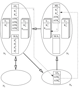
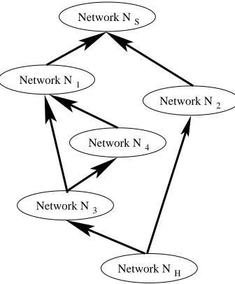
2.1 An autonomous network. . . 15 2.2 The Kerberos logo. . . 16 2.3 A Kerberos realm. . . 17 2.4 Steps 1 and 2 of Kerberos in action. . . 18 2.5 Steps 3 and 4 of Kerberos in action. . . 18 2.6 Steps 5 and 6 of Kerberos in action. . . 19 2.7 Steps 1 to 4 of multiple realm Kerberos in action. . . 20 2.8 Extra steps, steps 5 and 6 of multiple realm Kerberos in action. . . 20 2.9 Steps 1 to 4 of multiple realm Kerberos in action. . . 21 2.10 Extra steps, steps 5 and 6 of multiple realm Kerberos in action. . . 21 2.11 Hierarchical arrangement of Realms for cross-realm authentication . . . 22 2.12 The Eduroam logo. . . 24 2.13 Action of Eduroam for a user in home network . . . 25 2.14 Action of Eduroam for a user in a visited network . . . 26 2.15 Tunneling of Eduroam for a user in a visited network . . . 27 2.16 Authentication for a mobile user. . . 28 2.17 Mobile user calling a home network user. . . 29 2.18 Home network user calling mobile user. . . 29 2.19 Mobile user calling another mobile user. . . 30 2.20 Authentication Process for OpenID . . . 33 3.1 A typical autonomous network. . . 38 3.2 A Service Network Graph . . . 40 3.3 Attaching one network to another network . . . 45 3.4 User requesting a local service . . . 46 3.5 User requesting a shared service . . . 47 3.6 User requesting a shared service . . . 48 3.7 Mobile user requesting a shared service . . . 49 3.8 Changes in user authorization is pushed to server . . . 54 4.1 Sharing of key before SPath optimization . . . 63
7.1 DP Sevents for a principal . . . 97 7.2 Causal links betweenDP Sevents for principal A and B . . . 98 7.3 A DPS Bundle . . . 98 8.1 OMNeT++ configuration files forSNGsimulation. . . 118 8.2 OMNeT++SNGnetwork model for user at home network. . . 119 8.3 Routing logic for the simulation. . . 131 8.4 Simulation Topology for user at home network. . . 132 8.5 Simulation Topology for user at a visited network. . . 133 9.1 SNGtopology used . . . 136 9.2 Logical topology ofSNGshowing the authentication delegations. . . 138 9.3 User accessing Home Network services at Home Network. . . 139 9.4 User accessing Foreign Network services at Home Network. . . 140 9.5 User accessing Network services at a Foreign Network. . . 140 9.6 User accessing Network services at a Remote Network. . . 141 9.7 Logic diagram of the client program. . . 142 9.8 Diagram of algorithm used by the asServer program. . . 144 9.9 Diagram of algorithm used by an appGroup program. . . 145 9.10 Diagram of algorithm used by an application program. . . 146
Chapter 1
Introduction
According to the Computer Crime and Security Survey [19] conducted by Computer Secu-rity Institute and Federal Bureau of Investigation (FBI) in 2005, the average loss per year due to unauthorized access to information is about US$300,000 per respondent of the sur-vey. The situation has not been improved ever since - a similar survey [65] conducted in 2008 indicates that the average loss per year due to computing security incidents is only slightly under US$300,000 per respondent. These figures highlighted the severity and im-portance of network security, especially authentication, authorization and revocation of ac-cess rights. Without doubt, security issues become even worse and more complicated when networks are dynamically joined together to share their services. It motivated us to explore the practical solution to deal with the security of dynamic aggregations of heterogeneous networks which share services among each other.
1.1 Specific Problems
The complexity and insecurity of distributed networks system are manifested in various ways. For instance, some are related to the user authenticity; some are related to user authorization; while others are related to service availability.
When a registered user 1 of a network requests a service, the user first checks if the
service is available or not. Then the second and third steps would be authenticating the user and verifying if the user is authorized to use the service or not. Furthermore, during service access, relevant parties have to check continually if the user authentication and / or authorization has been revoked or not.
1A registered user refers to a user who has been registered as a legitimate user to the current network. In
this thesis, we always refers to a registered user wherever a user is mentioned.
When some autonomous networks are linked together for the purpose of sharing ser-vices, the situation is similar. Because the networks are autonomous, some of the important questions to ask are:
• who confirms availability of a service?
• who authenticates the user?
• who authorizes the user?
• how revocation can be executed?
1.1.1 The Availability of a Service
Within an IP network community, a user needs to register himself with a local network to enjoy all the services which are available on the network. The range of services available is often a determining factor for a user when choosing a network. However, it is difficult or impossible for one network to provide users with all the services its users want to use due to technological and financial limitations. To overcome these constraints, the range of services is supplemented by those provided by other autonomous networks. When users make a request of a particular service, they often are not sure if such a service is available or not; and even if available, where to get the service.
The services that are available on an autonomous network are usually listed and dis-tributed to its registered users. Problems may arise when a service is shared. It is easy to understand the fact that users of the Service Providing Network (SNet) are aware of the services. However, users of another network which share the services may not be aware of the services. It is desirable to provide users with the services available along with related service information at the time when they approach network for services.
When a network changes its range of services shared with other networks, it is impor-tant to timely update all service lists in networks. It will be disastrous if a user requests and then waits for a service which is not offered any more. In a dynamic aggregation of networks, it is critical to keep the service list up to date as the configuration of the aggregate changes.
1.1.2 The Authentication of a User
Authenticating a user who requests a service is by no means a trivial task. It is, however, not a big deal if the user is currently located in his home network (HNet), and requests a service which is available from his home network. However the case is not as straight forward when the user is visiting other network (V Net). Using the jargons, we may say in the first case,V Net, SNetandHNetare all the same. In the second case, V Net, SNet
1.1. SPECIFIC PROBLEMS 3
When the user is not in his home network, who is going to authenticate the user when the user is not in his home network, and how?
• Autonomy of NetworksTo authenticate a user, a network must share some common secret authentication information with the user. As we know, authentication infor-mation repository of one network is owned by the individual network. Furthermore, individual autonomous network can have different authentication schemes which re-quire different sets of authentication information.
When a user requests a shared service from a service providing networkSNet, the user has to identify himself to SNet. If SNet happens to be the HN et, SNet /
HNet can authenticate the user. OtherwiseSNet has to be informed and trust the result of authentication performed by another network.
When a user is at his HNet (V Net equals to HNet), authentication can be done by HNet and the result be sent to SNet. It only involves one layer of trusting relationship. When the user is not in his home network, (V Netnot equal toHNet), authentication request must be sent fromV NettoHNetand the authentication result forwarded toSNet. If he is currently not located within his home network, he may not be able to contact his home network for authentication. Authenticating the user is not a trivial task.
It is practically not feasible for all networks to be able to authenticate all users. Pri-vacy, compatibility of authentication schemes, and scalability are just few of the issues which forbid such a global authentication fantasia. Authenticating a user that registered in another network is the determining factor for successful service sharing. Authenticating a user by password is a simple and traditional approach. This ap-proach has limitations. Apart from the difficulty of remembering a password, an-other limitation of password is the scalability. To verify a password, we need to share some common secret information with the authentication server within a particular autonomous network. The shared information may not be available to authentication servers in other autonomous networks. Thus users may not be able to authenticate themselves when trying to use services in other autonomous networks.
Setting up and updating a common set of shared secrets for all users in all networks is impracticable.
• Scalability of Aggregation of Networks
aggregation of networks, we should look for a configuration that allows the aggrega-tion to grow and the member networks can still share their services efficiently among themselves.
• Heterogeneous Authentication Schemes
Different autonomous networks have different authentication schemes, different for-mats of shared information and different authentication client software. To access services in different networks, users may have to install various authentication client software and share different common secret information with different networks.
• Unfriendly Passwords
Legitimate users need to be authenticated before using services provided by the dis-tributed networks system. As we stated before, password is a common and readily accepted authentication token which allows user to access the networks system and makes network services available to legitimate users. Password themselves have two extremes. A friendly password is something easy to remember which usually means easy to crack. On the other hand, a strong password could be long with a short life time [53]; it means that strong passwords are harder to remember. So when com-posing a password, we face the dilemma of user friendly passwords are weak while strong passwords are hard to remember. This dilemma inspires us to design a pass-word scheme [33] in which the passpass-words are strong but easy to remember and with a short life time, effectively a one-time password [20].
1.1.3 Authorization Relay
Service provider networks (SNet) may choose to deliver selected services to nominated networks only. Authorization of a user helps to filter the legitimate users from the rest.
There is another form of authorization, sharing authorization. Apart from simple sharing, a network can act as an agent for service sharing. Suppose a SNet provides a serviceServiceand shared withNetA. A third networkNetBmay request to useService viaNetA. If theSNet is willing to shareServicewith all service requests coming from
NetA, it provides the service. On the other hand, if theSNet is willing to shareService with service requests coming from users ofNetAonly, it declines the request.
1.1.4 Reluctance of Authentication for Roaming Users
1.1. SPECIFIC PROBLEMS 5
1.1.5 Revocation of a User
User revocation information should be passed on to a service providing networkSNetin a timely fashion. The common approach of updating user revocation information is either on a regular time interval basis or during initial authentication, however, this approach is not efficient and not effective [49] [70].
• Total Revocation of Rights
If a user is revoked of all its right, it is equivalent to revoking its authentication status. When a user logs in, an authentication server checks the user’s login information and authenticate the user as required. The login status of the user changes from “not authenticated” to “authenticated” and remains so until the login session ends. For revocation to come to effect, the authentication server has to be aware of the revocation and act accordingly. Since authentication servers check the authentication and revocation information when users log in, the earliest time to revoke a user’s authentication status is the next log in even if the revocation information was updated some time ago. If a revoked user is currently logged in, (s)he can still use a requested service until the session ends.
• Partial Revocation of Rights
It is common for the servers to check authentication and authorization only when requests for services are received. The servers provide service to authenticated and authorized requests until the service sessions end without checking authentication and authorization while the session is still alive. When a user is using a service with certain user rights, it retains its user rights until the service session ends.
If a user is denied some or all of the user rights to services which it is currently accessing, it would not be denied of the rights until the server has updated its access control information and the service is accessed by the user next time.
The time gap between revocation and actual banning of user from services may lead to potentially disastrous damage.
1.1.6 Mobility of Users
1.2 Related Work on the Problems
When a network provides a service to users of another network, the service is said to be shared and the network is a service providing network (SNet). When a network includes a shared service as part of its services, the shared service is said to be an out-sourced service and the network is a service requesting network.
A service providing network has to establish the identity of a user requesting a service. Many plausible technologies are proposed. We look at some of the prominent ones.
• A Common Authentication Information Set: When many autonomous networks form an aggregation for service sharing, the network administrators face a problem of authenticating users from other networks which have various authentication schemes and authentication information sets. It is obvious that enforcing a common authenti-cation scheme is not feasible and involves substantial administrative overheads. For instance, when a network links to an aggregation of networks and subsequently de-taches from the aggregation, switching to the common authentication scheme and reverting back to the original authentication scheme requires all users of the network to collect and present a different set of authentication information. Even a common authentication scheme is in force, maintaining a global set of authentication data will fail as networks may link to the aggregation or detach from the aggregation at any time. Even worse, some networks may be reluctant to disclose the authentication data for security reasons. As a direct result of this, other networks may not have the authentication data required by the common authentication scheme. A typical exam-ple is the X.500 [1] plan which has never succeeded in producing a global database of named entities.
• Secrecy of the Private Key: Authentication in X.509 [2] is based on the secrecy of the private key and the binding of the public key to a user name. For instance, a Certificate Authority (CA) authenticates a user and binds its name and public key in a digital certificate. If a user demonstrates he is the owner of the private key with a corresponding X.509 certificate, then he is the user named in the certificate. This authentication mechanism is built upon the unanimous trust for the Certificate Authority (CA).
Note that an administrator of an autonomous network may decide to set up a CA for the network or empower a third party to run the CA. However, when many au-tonomous networks form an aggregation, they must agree on a common CA to issue all certificates or on CA certificate chaining. We envisage that the workload increases with the number of users involved.
1.2. RELATED WORK ON THE PROBLEMS 7
by an observer. When an observer is authorized by a network administrator to give trust recommendations [48] [67], the observer becomes atrust agent. The trust is represented by a token and each trust token is signed by thetrust agent.
It is reasonable for each autonomous network to have its own set of independent trust agents. A user is asked to provide trust tokens by a few trust agents. By using the ag-gregated result [7] [15] of the trust tokens, the server can determine the authentication and authorization status of the user for the requested service.
This way of authentication works fine for individual networks. However, for an aggregation of networks, each autonomous network may have its own set of trust agents. Either all the networks adopt the same common set of trust agents or users have to collect trust tokens from different sets of trust agents for services out-sourced by different networks.
• Central Authentication Server: Kerberos [51] presented a user friendly solution in which users authenticate with a central authentication server and the authentication status can be propagated to the required servers. With one set of authentication infor-mation and one log-in, users would be able to access services available from servers within the same realm.
The problems with this approach is that users have to keep track of the availability of services as they have to specify which server and service they want to access. Users must maintain an updated list of services available by themselves.
Secure European System for Applications in Multi-Vendor Environment, com-monly known asSESAME, is often considered as the Euro version of Kerberos. It is a single sign-on project funded partially by the European Commission. It uses Privilege Attribute Certificates and supports different security policies across multi-domains.
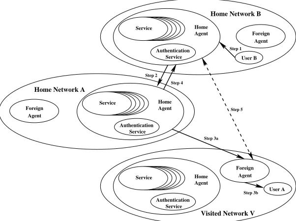
• Eduroam: Eduroam provides wireless service to users roaming between participat-ing institutions. The Home network authenticates the user and the service providparticipat-ing network determines the authorization to use local network resources. The authenti-cation technology used by Eduroam is based on 802.1X and Remote Authentiauthenti-cation Dial In User Service (RADIUS) proxy servers.
As Eduroam shares wireless access with a user, the user has to move himself to a location within the range covered by the wireless LAN in order to use the shared service. Another main drawback of Eduroam is that the shared services is still limited to public services only.
HA. When he moves to another network, he has to connect to the FA of the visited network which forwards his user information and credentials to the HA of the user’s home network for authentication. The main drawback of Mobile Host Routing is that it applies to networks linked together on a network by network basis. It cannot be applied to ad hoc aggregation of networks.
• OpenID:
OpenID 2 authentication is simply a confirmation process for the ownership of an
Identifier which is assigned by an OpenID Provider (OP). Each OP has its own requirements for setting up an OpenID account. Most of them just require a username and password. Note that there is no binding of identity required.
OpenID can assert that you own theIdentif ieryou presented, but what thatIdentif ier
represents is in limbo.
• Strong and Friendly Password:
The classic password protocol Encryption Key Exchange (EKE) by Bellovin and Merritt [9] and its successor Augmented-EKE (A−EKE) [10] is a collection of au-thentication protocols that apply encryption for key exchanges. EKE uses a shared secret indirectly to authenticate servers and users. HoweverEKE is susceptible to the Denning-Sacco attack [69] in which a stolen session key can be used to launch a replay attack on the password. A more efficient Minimal Encrypted Key Exchange (M −EKE) [69] was proposed.
Other alternatives to A −EKE were proposed. Strong Password-Only Authenti-cated Key Exchange (SP EKE) [25] uses the hash of the password as the base for exponentiation instead of a fixed primitive base. Extended Password Key Exchange Protocols [26] is a family of protocols that extend theA−EKEandSP EKE pro-tocols toB−EKE andB −SP EKE by using a second Diffie-Hellman exchange instead of a digital signature to prove that a user has knowledge of a certain password. Open Key Exchange (OKE) [46] eliminates the use of encryption for the user’s pub-lic key. Another feature ofOKE is that the user’s public key can be reused as long as the private key is kept secret. Asymmetric Key Exchange (AKE) [78] is another class of protocol that exchanges keys without using encryption. Initially, each party computes a secret and generates a verifier with a one-way hash function. They swap their secrets and use them as long term swapped secrets. For each session, each party generates another session secret and swaps with the other party. The session key is generated from the swapped long term and session secrets. Authentication is completed when both parties confirm that they have the same session key.
2Formed in June 2007, OpenID Foundation (http://openid.net/foundation) promotes the OpenID
1.3. A PRACTICAL EXAMPLE OF SERVICE SHARING 9
All the above password protocols do not offer transmission of new password.
1.3 A Practical Example of Service Sharing
In this section, we give a real life example which illustrates some of the problems stated previously.
1.3.1 Background
Hong Kong and Macau are the two Special Administrative Region (SAR) of the People’s Republic of China [14]. They enjoy a high degree of autonomy and have executive, leg-islative and independent judicial power. In particular they maintain their customary law previously in force. As a result, Hong Kong and Macau have different and independent custom laws and regulations.
When a resident of Hong Kong leaves or enters Hong Kong, he can use the biometrics based Automated Passenger Clearance System [24] (e-channel for short) and identifies himself using his own prints [55, 45]. The e-channel system matches the finger-prints captured by a scanner with a digitized version stored in the Hong Kong Custom in-formation repository. Macau Public Security Forces Bureau still uses the traditional manual passport inspection system and is moving towards the same e-channel system as that im-plemented in Hong Kong [44]3. Hong Kong residents can authorize Macau custom to get
a copy of their finger-prints from Hong Kong custom. A resident of Hong Kong can use both the traditional manual passport inspection system and the e-channel system after the finger-prints are transferred to Macau custom.
1.3.2 Authentication Information Sharing
This is what happens in reality. When a resident of Hong Kong heads for Macau, he has to use the e-Channel when he leaves Hong Kong. At the custom of Macau, he can either use existing manual passport inspection system or the newly implemented e-channel. If he chooses to use the passport system, the resident has to have two sets of identity information for the two authentication systems - passport / Identity Card to be used in Macau and finger-prints to be used in Hong Kong.
If the resident wishes to use the new Passenger Clearance Service for entry to Macau, he can use a single set of identity information for both Macau and Hong Kong. The authentica-tion informaauthentica-tion stored in Hong Kong Custom will then be copied and shared with Macau Custom. However, both Hong Kong custom and Macau custom must have an identical but
3More information about the hardware and the supplier can be found in
independent copy of the resident’s finger-prints. The transfer of identity information and finger-prints has to be done manually and takes up to three working days after the resident made an initial application for the transfer. It can be error prone and not scalable if you consider the fact that there are seven million residents in Hong Kong.
1.3.3 Service Sharing
The Passenger Clearance Service is not shared. The use of the same Passenger Clearance System hardware and having independent copies of identical information can be compared to the case of networks using the same authentication scheme. The participating networks use the same authentication scheme but each network keeps an independent copy of au-thentication information which are identical. It is definitely better than two autonomous networks with different authentication schemes and authentication information formats.
On the other hand, if the Passenger Clearance Service is truly shared, any Hong Kong resident can authenticate himself using the Passenger Clearance Service provided by Hong Kong and authentication information stored in Hong Kong Custom when they enter or exit Macau. No massive transfer and duplication of authentication information between two SARs are required. This will prevent security loop holes associated with updating, synchronizing and revoking authentication information.
1.4 Research Contribution
This research is targeting the authentication, authorization, revocation of rights and mobil-ity issues of service sharing. The outcomes from this study are as follow:
1. A secure and scalable user authentication framework for service sharing within a dynamic aggregation of autonomous networks. The details can be found in the fol-lowing refereed publications:
• An infrastructure for service authentication and authorization revocation in a dynamic aggregation of networks. WSEAS Transactions on Communications, 4(8):537-547, August 2005.
• Network service sharing infrastructure: Service authentication and authoriza-tion revocaauthoriza-tion. Proceedings, the 9thWSEAS Internaauthoriza-tional Conference on Com-munications, July 2005. (CD Proceedings)
• Secure service sharing over networks for mobile users using service network graphs. Proceedings, Wireless Telecommunication Symposium 2006, Pamona, Ca, USA, April 2006. (CD Proceedings)
1.4. RESEARCH CONTRIBUTION 11
• Towards an authentication protocol for service outsourcing over ip networks. Proceedings, the 2005 International Conference on Security and Management, (7):3-9, June 2005.
• Efficient information propagation in service routing for next generation net-work. Proceedings, The Fourth International Conference on Rough Set and Knowledge Technology, pages 342-349, 7 2009.
2. A relatively strong but easy password scheme to be used as a standalone authenti-cation scheme or in conjunction with the proposed secure authentiauthenti-cation framework for service sharing. More details can be found in the refereed publication:
• Integrated key exchange protocol capable of revealing spoofing and resisting dictionary attacks. Technical Track Proceedings, 2nd International Conference, Applied Cryptography and Network Security, Yellow Mountain, pages 115-124, June 2004.
3. A theoretical proof for the correctness of the proposed secure authentication frame-work.
4. A formal proof for self-authentication of a communication channel in which the traf-fic is encrypted. This proof forms part of the basis for the correctness of the secure authentication framework. More details can be found in the refereed publication:
• Self-authentication of encrypted channels in service network graph. Proceed-ings, 2008 IFIP International Conference on Network and Parallel Computing, pages 163-167, (NPC 2008), October 2008.
5. A formal proof that service records used in the secure authentication framework can be optimized. This proof shows that the secure authentication framework is efficient and scalable. The details can be found in the following refereed publications:
• Improving efficiency and scalability of service network graph by re-routing. Proceedings, 1st Asian Conference on Intelligent Information and Database Systems 2009, (CD Proceedings), 4 2009.
• Service re-routing for service network graph: Efficiency, scalability and im-plementation. International journal of Computer Networks Communications (IJCNC). ISBN (on-line) 0974-9322. ISBN (print) 0975-2293., 1(1), 4 2009.
6. Two case studies:
• A practical application of the basic features of the proposed secure authentica-tion framework using C++.
1.5 Structure of the Dissertation
We have gone through from the issues associated with the service sharing over IP net-works to the design of Service Network Graph, the Dynamic Password, the Key Exchange using Dynamic Password protocol and to the application of the Service Network Graph and Key Exchange using Dynamic Password protocol on aggregates of heterogeneous net-works. In Chapter 2. The technology reviewed includesKerberos, Sesame, Eduroam,
Mobile Host Routing and OpenID. We comment on the drawbacks of each
technol-ogy when used for the purpose of service sharing for ad hoc aggregates of autonomous networks.
In Chapter 3, we propose the Service Network Graph. An Service Network Graph with the simplest logical topology is established when a network delegates its authentication authority to another network by sharing an authentication Token key with the other network. Services are then shared. Information about the shared services are recorded as Service Paths.
The next chapter, Chapter 4, focuses on a Service Path. Optimizing Service Paths makes them more scalable and efficient. In this chapter, the way to optimize an Service Path is presented and a formal proof of the optimization process is also include.
When a network joins an Service Network Graph, authentication authorities are del-egated to (and by the joining network). Participating networks can track the origin and destination of authentication tokens sent and received because encrypted channels authen-ticates themselves. In Chapter 5, a formal proof of the self-authentication of encrypted channels is given.
Service Network Graph is designed such that individual network can have their own au-thentication scheme. Nevertheless, username and password pair is by far the most common authentication information in our daily life. In view of the weakness in common password schemes, we proposed Dynamic Password scheme which is effectively a onetime password scheme in Chapter 6. The associated Key Exchange using Dynamic Password scheme is also discussed.
Chapter 7 justifies Service Network Graph using Dynamic Password as a correct secu-rity protocol using the concept of Strand Space. The correctness can be proved by demon-strating that Service Network Graph using Dynamic Password has the secrecy and agree-ment properties. The correctness claims are presented as propositions and the proofs are built up from series of lemmas.
As an illustration, we simulate the Service Network Graph process usingOM NeT+ +
1.5. STRUCTURE OF THE DISSERTATION 13
home network and in a visited network.
In Chapter 9 we presented a simple implementation of Service Network Graph using Dynamic Password. Virtual Local Area Network and a ”Router on a stick” configuration is used for the physical networking, and the services shared are simple time, date, echo and name services.
Chapter 2
Service Sharing Technologies
In this Chapter, we take a brief look at some of the existing technologies for service sharing among autonomous networks. We comment on the draw backs of each technology when they are applied in the context service sharing.
2.1 Autonomous Network
The first technology is on an autonomous network. An autonomous network operates under the control of a singleadministrative domain. An autonomous network has its own au-thentication scheme and auau-thentication credential repository as shown in Figure 2.1. Each network can only authenticate and authorize registered users only.
User (U)
Wireless Service
Autonomous Network
Service Authentication
Service
Figure 2.1: An autonomous network.
Some autonomous networks provide services only to their members; whilst some pro-vide limited services to the public. Users must register to a given network to access all its services. Services shared across networks are limited to the public services offered by each network.
2.2 Intranet and Internet
As the second technology, we have Intranet and Internet. An Intranet usually connects networks within an organization. The inter connected networks function like an extended network sharing the same services and authentication information and scheme.
Internet is a global interconnection of networks. Basically, each network acts like an autonomous network and offers limited services to the public and other networks. In most cases, public services are provided along side with advertizement to cover the running cost, while some services gather user’s personal information for commercial use. When authentication is requested by a network, the authentication schema and the authentication data repositories used are basically independent of each other. The authentication data may vary from simple user account name and password or public and private key to biometric and token authentication [24].
Sharing of services on Intranet and Internet are limited to public services only.
2.3 Kerberos
Figure 2.2: The Kerberos logo.
When a user is authenticated in his home realm (equivalent to his home network), other realms (or networks) within the Kerberos1system accepts the user’s identity if cross-realm
operation is enabled.
1Kerberos is the network authentication protocol developed by Massachusetts Institute of Technology
2.3. KERBEROS 17
Kerberos is based in part on Needham and Schroeder’s trusted third party authentication protocol [50]. Users in the Kerberos Protocol are calledprincipals. The identity credential of each Principal is represented electronically as aticket. The main component of Kerberos is the Key Distribution Center (KDC). AKDCconsists of two servers, the Authentication Server (AS) and the Ticket Granting Server (T GS). Each entity, including principals and servers, shares a secret (a password) with the Key Distribution Center for authentication purpose. Principals whose authentication data are registered with a given Key Distribution Center are said to belong to the same realm.
Figure 2.3 depicts the basic structure of a Kerberos realm.
Service Server (S)
User (U)
Kerberos Realm
Ticket Granting Server (TGS) Authentication
Server (AS)
Key Distribution Centre (KDC)
Figure 2.3: A Kerberos realm.
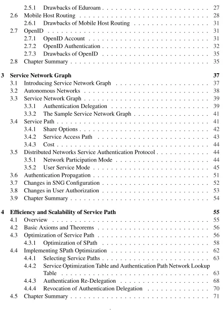
The Kerberos authentication process consists of six steps as shown in Figure 2.4, Fig-ure 2.5, and FigFig-ure 2.6.
Step 1 A user sends a plain text Authentication Request to AS for credentials to use services. Both the user and the service information are included in the request.
Step 2 An AS retrieves the shared secret of the user from the authentication data repository. It also generates a TGS session key. The AS returns two messages to the principal. The first one is anAuthentication Reply message formed by encrypting the TGS session key using the user key generated from the shared secret of the user. The second message is the TGS session key encrypted using the secret key of TGS and is called theT icket Granting T icket(T GT). This TGT is the credential to access services.
Step 3 After receiving the Authentication Reply, the user can use his shared secret to recover the TGS session key. The user also uses two messages to communicate with the TGS. The first message is a Service Request made up of service information and the TGT. The second message is an Authenticator formed by encrypting the user information and a time stamp with the TGS session key just recovered from the
Service Server (S)
Key Distribution Centre
Ticket Granting Server (TGS) Authentication
Server (AS)
User (U)
Ticket Granting Ticket
TGS session key TGS key User information Step 2
Step 1 Authentication Request
User information
U key Authentication Reply
TGS session key
Figure 2.4: Steps 1 and 2 of Kerberos in action.
Service Server (S)
Key Distribution Centre
Ticket Granting Server (TGS) Authentication
Server (AS)
User (U)
Service information
Ticket Granting Ticket
Service Request TGS session key Authenticator
User information
Time stamp Service Access Ticket
S key User information
S session key
Step 3
Step 4
Service Reply
[image:42.595.160.325.118.288.2]TGS session key S session key
Figure 2.5: Steps 3 and 4 of Kerberos in action.
Step 4 TGS decrypts the TGT inside the Service Requestand gets the TGS session key for this session. Using the TGS session key just recovered, TGS can retrieve the user information from theAuthenticator. Similar to AS, TGS generates a service server (S) session key; encrypts the S session key and user information using the shared secret of S to form a Service Access T icket; encrypts the S session key using the TGS session key to form aService Reply. TheService Access T icketis the credential to access the requested service of a given server.
Step 5 The user retrieves S session key using the TGS session key. The user now forwards
2.3. KERBEROS 19
Service Server (S)
Key Distribution Centre
Ticket Granting Server (TGS) Authentication
Server (AS)
User (U) Authenticator
S session key User information
Time stamp
Service Reply Time stamp + 1
S session key Service Access Ticket
S key User information
S session key
Step 6
Step 5
Figure 2.6: Steps 5 and 6 of Kerberos in action.
Step 3but using the S session key.
Step 6 The service server S confirms the service is available by returning aService Reply
fomred by encrypting the time stamp from the Authenticator plus 1 with the S session key.
Upon completion of these six steps, the user can now access the service provided by S.
2.3.1 Cross-Realm Operation of Kerberos
Kerberos enables users of one realm to access services provided by another realm. This is called cross−realm operation. To facilitate the cross-realm operation, the KDC from one realm must share an inter-realm key with the KDC of another realm. When realms share inter-realm keys with another realm, they established themselves as a principal of the other realms.
S S Kerberos
Realm B
U
U Kerberos Realm A
KDC
TGS AS
AS TGS
KDC
Figure 2.7: Steps 1 to 4 of multiple realm Kerberos in action.
There might be two extra forwarding steps, and the extra forwarding steps are shown as Step 4a and 4b in Figure 2.8.
S S Kerberos
Realm B U
U Kerberos
Realm A
KDC
TGS AS
AS TGS
KDC
Steps 4a and 4b Steps 5 and 6
Figure 2.8: Extra steps, steps 5 and 6 of multiple realm Kerberos in action.
Note that the cross-realm operation is transitive, which means, for example, as shown in Figure 2.9 and 2.10,
• Realm A shared an inter-realm key with Realm B;
2.3. KERBEROS 21
• Realm D shared an inter-realm key with Realm C;
The TGT sequence for cross-realm authentication is from Realm A to Realm B, then to Realm D and finally to Realm C as follows:
S S S Kerberos Realm B U U U S U KDC Kerberos Realm D TGS AS Kerberos Realm A KDC TGS AS Kerberos Realm C KDC TGS AS AS TGS KDC
Figure 2.9: Steps 1 to 4 of multiple realm Kerberos in action.
S S U S Kerberos Realm B U U S U KDC Kerberos Realm D TGS AS Kerberos Realm A KDC TGS AS Kerberos Realm C KDC TGS AS AS TGS KDC
Steps 4a and 4b
Steps 4c and 4d Steps 4e & 4f
Steps 5 & 6
Figure 2.10: Extra steps, steps 5 and 6 of multiple realm Kerberos in action.
Steps 1 to 4 A user from Realm A authenticates himself to the AS of Realm A and gets
T GTAas shown in Figure 2.9.
Steps 4a and 4b The user forwards theT GTAto TGS of Realm B and getsT GTB.
Steps 4c and 4d The user forwards theT GTBto TGS of Realm D and getsT GTD.
Steps 4e and 4f The user forwards the T GTD to TGS of Realm C and in return gets a
Steps 5 and 6 The user uses theService Access T icketto access service in Realm C just like accessing service in Realm A.
The extra steps are used to forward TGT between KDCs of successive communicat-ing pairs of realm. A database may be required to keep track of the possible authentica-tion paths. If the communicating realm pairs can be organized hierarchically as shown in Figure 2.11, authentication paths of minimal length can easily be worked out using the hierarchy.
...
...
...
Realm 11
Realm 01
Realm 12
Realm 21 Realm 22 Realm 23 Realm 24
Realm 31 Realm 32
Figure 2.11: Hierarchical arrangement of Realms for cross-realm authentication
2.3.2 Kerberos V5 Applications
The functionality of Kerberos is extended by various Internet Standards such as [80, 75, 82, 83, 81, 47, 76, 29]. Popular applications based on Kerberos V5 includes:
• User interface to TELNET protocol - telnet
• Remote login - rlogin
• File transfer program - ftp
• Remote shell - rsh
• Remote file copy - rcp
2.4. SESAME 23
2.3.3 Drawbacks of Kerberos
Although Kerberos has been used for many purposes, there are some technical limitations.
• Each network must be Kerberized before joining, which means each network must 1. Implement a KDC including an AS and a TGS
2. Service Servers must accept Service Access T ickets and Authenticator as the credential for using services.
This certainly limits the use of Kerberos for dynamic aggregation of heterogeneous networks.
• Each realm KDC has to keep track of the TGT paths for service tickets.
• Hierarchical organization of KDC could make the traffic heaviest at the top level.
• Hierarchical (tree like) organization of KDC could suffer single point of failure.
• Mesh organization of KDC for cross-realm authentication makes the complexity of inter-realm key management increase exponentially with the number of networks involved.
• Users have to keep track of the availability of services as they have to specify which server and service they intended to access. As a result, users must maintain an up-dated list of services available by themselves.
• The administrative work involved in setting up realms makes Kerberos semi-static. If autonomous networks are to attach and detach from an aggregate of networks in a dynamic fashion, we need a more efficient solution.
2.4 SESAME
In this section, we look at SESAME2, Secure European System for Applications in
Multi-vendor Environment [31, 54]. SESAME is a single sign-on project partly funded by the European Commission. It authenticates users and issues Privilege Attribute Certificates. When operating in a multi-domain environment, it supports different security policies across the domains.
The operation of SESAME is similar to Kerberos. The authentication process for SESAME version 2.0 is listed below:
Step 1 A user authenticates to anAuthentication Server.
Step 2 TheAuthentication Serverreturns an encryptedIdentity T okento user.
Step 3 The user presents theIdentity T okento aP rivilege Attribute Server.
Step 4 The P rivilege Attribute Server returns a digitally signed P rivilege Attribute
Certif icate(P AC) to user.
Step 5 The user presents aP AC to the application server.
Step 6 The Application server provides services according to the security attributes in the
P AC and its own security policies.
A PAC can be used more than once at more than one application server. Recall that Kerberos key distribution protocols can be used to establish session keys between users and servers.
The major feature Sesame offers which Kerberos does not is the use of PAC. With the PAC, application servers can implement their own fine grain access control and audit checks. The approach to security for SESAME was considered an alternative to the DES based security service in Distributed Computing Environment based on Kerberos [30].
Unfortunately, SESAME has similar drawbacks to that of Kerberos. We would not repeat them here.
2.5 Eduroam
Figure 2.12: The Eduroam logo.
2.5. EDUROAM 25
force started off by setting up the roaming policy [62] and inventory of existing technolo-gies [61, 60, 59, 58]. The Task Force eventually came up with the roaming architecture [63] and the implementation plan [64] in 2007.
Eduroam (Figure 2.12) aims to provide wireless service to users roaming between par-ticipating institutions. Authentication on the Eduroam is done by the home network and the authorization to use local network resources is determined by the network visited.
It is worth pointing out that the authentication technology used by Eduroam is based on 802.1X and Remote Authentication Dial In User Service (RADIUS) proxy servers. In more detail, when a user requests login, the authentication request is forwarded to the local authentication server.
User (U)
Service Server (S) Authentication
Server (AS)
RADIUS proxy Server
Accessing wireless
service Authentication
Request
Authentication Service
Eduroam Realm A
Wireless service
Figure 2.13: Action of Eduroam for a user in home network
If the authentication request can be processed locally, the user would be granted the authority to access the wireless services as shown in Figure 2.13.
Otherwise, the local authentication server forwards the request to a RADIUS proxy server. As all the RADIUS proxy servers are organized in a hierarchical order, it is simple to traverse the hierarchical tree of proxy servers to reach the RADIUS proxy server of user’s home network. An example path taken is shown in Figure 2.14.
1. National RADIUS proxy Server 34; 2. Regional RADIUS proxy Server 22; 3. Top level RADIUS proxy Server 11; 4. Regional RADIUS proxy Server 21; 5. National RADIUS proxy Server 31;
Authentication Server (AS)
RADIUS proxy Server
Authentication
Service Service
Server (S) Wireless service User (U)
User (U)
Wireless service Service Server (S) Authentication
Server (AS)
RADIUS proxy Server
Authentication Service
Eduroam Realm A
RADIUS proxy Top level
Server 11
Eduroam Realm B
...
RADIUS proxy National RADIUS proxy
National
RADIUS proxy Regional
RADIUS proxy Regional
RADIUS proxy National RADIUS proxy
National
Server 21 Server 22
Server 33 Server 32
Server 31 Server 34
Figure 2.14: Action of Eduroam for a user in a visited network
policy of the visited network, the user may access the wireless service and other network resources of the visited network.
As we mentioned in the preceding section, Eduroam uses 802.1X which encompasses the uses of Extensible Authentication Protocol (EAP). Eduroam supports the use of Trans-port Layer Security (EAP-TLS), Tunneled TransTrans-port Layer Security (EAP-TTLS), and tected Extensible Authentication Protocol using Challenge Handshake Authentication Pro-tocol (PEAP-EAP-MS-CHAP V2) as the authentication proPro-tocols.
2.5. EDUROAM 27
Authentication Server (AS)
RADIUS proxy Server Authentication
Service
User (U)
Eduroam Realm B
Wireless service Service Server (S)
User (U)
Wireless service Authentication
Server (AS)
RADIUS proxy Server
Eduroam Realm A
Service Server (S) Authentication
Service
Figure 2.15: Tunneling of Eduroam for a user in a visited network
2.5.1 Drawbacks of Eduroam
There is no doublt that Eduroam has some drawbacks. The drawback include
• Sharing of Wireless access only.
• The user has to move physically within the wireless LAN coverage before he can use the shared service.
• Sharing of other network resources is limited to public services only.
• Institutions have to register to the National RADIUS proxy server
• Enjoying home services only.
2.6 Mobile Host Routing
Mobile Host routing is another technology that supports service sharing.
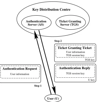
Mobile Host Routing (MHR) [71] deals with the problem of routing data to a mobile host by establishing a Home Agent (HA) and a Foreign Agent (FA) in a network. When the user is in his home network, he authenticates himself with the HA. When he moves to another network, he becomes a guest and he has to first connect to the FA of the visited network. The FA must request that the guest provides his user information and credentials; these requested information and credentials would be forwarded to the HA of the user’s home network as shown in Figure 2.16.
Logon Reuest
User Information
Time stamp User credentials
Logon Approval
User Information Time stamp
Service
Authentication Service
Home Agent
Agent Foreign Service