A
NALYSING
JPEG
C
ODING
W
ITH
M
ASKING
S.-Y. YEO and *Y.-Y. NGUWI
School of Business (IT), James Cook University Singapore
A
BSTRACTThe growing trend of online image sharing and downloads today mandate the need for better encoding and decoding scheme. This paper looks into this issue of image coding. Multiple Description Coding is an encoding and decoding scheme that is specially designed in providing more error resilience for data transmission. The main issue of Multiple Description Coding is the lossy transmission channels. This work attempts to address the issue of re-constructing high quality image with the use of just one descriptor rather than the conventional descriptor. This work compare the use of Type I quantizer and Type II quantizer. We propose and compare 4 coders by examining the quality of re-constructed images. The 4 coders are namely JPEG HH (Horizontal Pixel Interleaving with Huffman Coding) model, JPEG HA (Horizontal Pixel Interleaving with Arithmetic Encoding) model, JPEG VH (Vertical Pixel Interleaving with Huffman Encoding) model, and JPEG VA (Vertical Pixel Interleaving with Arithmetic Encoding) model. The findings suggest that the use of horizontal and vertical pixel interleavings do not affect the results much. Whereas the choice of quantizer greatly affect its performance.
K
EYWORDSJpeg, image, coding, masking, mdc
1.
I
NTRODUCTIONThe use of internet and mobile networks increases exponentially. Transporting image and video over the internet while guaranteeing content and speed is a challenging problem. The difficulty can be attributed to the size of image and video are often much larger than other forms of transmission. When an image or video is transmitted through internet, it is first encoded into several packets using progressive encoding scheme like Joint Photographic Expert Group (JPEG). Encoded packets are then delivered using Transmission Control Protocol (TCP), the standard protocol that controls retransmission of lost packets. When a transient error occurs, decoder fail to decode and re-construct the original signal due to loss of packets.
Fast Multiple Description Coding (FMDC) is an encoding and decoding scheme that is specially designed in providing more error resilience for data transmission. It encodes a source into two or more independent bit streams known as descriptor and each descriptor carries crucial information and features of original source. This ensures that receiver is able to recover the original data with certain level of quality even if some descriptions are lost. Quality improves when more descriptions are received and decoded. As these transmission channels are often unreliable, the popularity of MDC coding has increased over the past few years. Multiple Description Coding typically consists of two phases: encoding phase and decoding phase. During encoding phase, the system divides and compresses an input image and develop descriptions to be transmitted through different channels. At decoding phase, if one of the descriptor is received, it will be decoded and original image is re-constructed with a low, but acceptable quality. When more descriptors are received, the image can be better constructed and produce a higher quality image.
sections: Section II presents some literatures related to image coding or transforms. Section III presents the system design and results.
2.
L
ITERATURER
EVIEWThis section reviews and summarizes some of the common techniques utilized by various researchers trying to improve the current technology. It focuses on two dimensional techniques like Two Dimensional Discrete Cosine Transform (2D DCT), Two Dimensional Discrete Wavelet Transform (2D DWT), Multiple Description Scalar Quantizer (MDSQ), Entropy Encoding and etc.
2.1. Two Dimensional Discrete Cosine Transform (2D DCT)
Discrete Cosine Transform (DCT) [1, 2] was first discovered and developed by Ahmed et. al. [3] in 1974. It is a technique that converts an input signal (e.g. Image’s pixel values) into frequency domain. DCT is widely used in image compression like JPEG, which is the first international standard for still image compression established in 1992. After transforming, the important information of an image concentrates at low frequency area. The less important information presents in higher frequency are then discarded. Human eyes are not sensitive to high frequency component. The file size of an image is reduced, however the quality is still acceptable. The disadvantage of 2D DCT is the introduction of blocking artefacts due to discarding of high frequency component during compression [4].
2.2. Two Dimensional Discrete Wavelet Transform (2D DWT)
Due to the blocking effects mentioned in previous section, JPEG introduced another type of image compression standard which is called JPEG2000 that is based on wavelet. Haar wavelet is used. The 2D Haar wavelet works by down sampling input image twice. First time along the rows, then along the columns. The second time using another sub-band. The 2D DWT has gained worldwide recognition in Digital Signal Processing because of the advantages listed below.
• Two dimensional DWT offers better compression rate and better re-construction of image
quality compared to 2D DCT.
• It does not have blocking artefacts.
• Rate of compression is scalable with multiple transformation levels.
Although 2D DWT is a better compression technique compared to 2D DCT, still many people choose to go for 2D DCT because the implementation of 2D DWT in terms of hardware and software is far more expensive and complex than 2D DCT [5].
2.3. Pixel Interleaving (PI)
2.4. Quantization
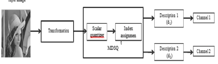
Quantization is a technique used to reduce the number of bits required to represent an image. It is a lossy compression technique employed in source encoder. Compression of an image can be accomplished by removing redundant information within the image itself, namely spatial redundancy, spectral redundancy, and temporal redundancy. For quantizer, there are scalar quantizer and multiple description scalar quantizer (MDSQ). Scalar quantizer rounds a floating point real value into an integer value depending on the step size. MDSQ generates two coarse descriptions simultaneously with every input image. It aims to re-construct the input image with the highest quality if both descriptions arrived at the decoder side successfully. As shown in Figure 1 is the basic architecture of encoding system using MDSQ.
[image:3.612.134.487.265.370.2]The performance of MDSQ depends on the spread of index assignment which in turn determines the amount of redundancy that a particular index assignment possesses [8].
Figure 1. Basic architecture of MDSQ encoding system.
2.5. Entropy Coding
Entropy coding is usually employed quantization to further compress quantized value for better compression ratio. It is a lossless compression scheme that creates and assigns a unique codeword to every unique symbol (pixel value) that occurs within an input image. Entropy coding assigns codeword according to the number of occurrence of a symbol. Symbol that occurs most frequently will be assigned the shortest codeword. Types of entropy coding includes Huffman Coding [9] and Arithmetic Coding [10]. Huffman coding compresses an image by encoding the original data into shorter code, each unique symbol is then given a unique prefix code and length of this code depends on the frequency of occurrence of that particular symbol. These prefix codes are then transmitted for decoding purposes over at the receiver side. Arithmetic coding uses symbol together with probability value that ranges from 0 to 1. The probability denotes the frequency of occurrence.
3.
T
HES
YSTEMA
NDR
ESULTS3.1. JPEG Coding
Figure 2. Images used in experiment
Figure 3. JPEG HH encoding model (Horizontal PI and Huffman Encoding)
Figure 4. JPEG HA encoding model (Horizontal PI and Arithmetic Encoding)
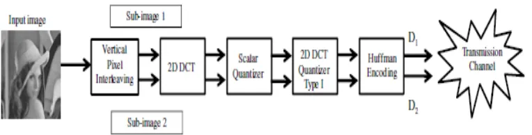
[image:4.612.125.504.399.517.2] [image:4.612.120.502.570.667.2]Figure 6. JPEG VA encoding model (Vertical PI and Arithmetic Encoding)
[image:5.612.224.397.511.673.2]Figure 7. JPEG decoding
Figure 8. Horizontal Pixel Interleaving
. (a) Original Image (512x512) (b) SubImage 1 (256x512) (c) Sub-Image 2 (256x512)
Figure 9. Vertical Pixel Interleaving.
Figure 3 illustrates JPEG HH encoding model using Horizontal Pixel Interleaving and Huffman Encoding. Input image is first interleaved into two sub-images. Figure 4 denotes JPEG HA encoding model using Horizontal Pixel Interleaving and Arithmetic Encoding. Figure 5 JPEG VH model uses Vertical Pixel Interleaving and Huffman Encoding whereas Figure 6 presents the JPEG VA coder using Vertical Pixel Interleaving and Arithmetic Encoding. The sub-images are then fed into 2D DCT for transformation, the transformed images are then quantized into smaller file size. The quantized coefficients are then entropy encoded individually to enhance bandwidth efficiency. Two descriptors D1 and D2 are created for transmission.
Figure 7 illustrates our JPEG decoding system. Decoding reverses the encoding process. Once the system received D1 and D2 descriptors, they will be entropy decoded, de-quantized, and undergone inverse DCT to retrieve back the original image. The interpolation part is needed for the case of only 1 descriptor is received due to transmission error.
The steps for encoding are summarized below:
Step 1: Input image is interleaved into two sub-images.
Step 2: Each sub-image is divided into many 8x8 blocks of pixels. Step 3: Apply 2D DCT to every block
Step 4: Convert points to integer through scalar quantizer for bytes reduction.
Step 5: Each block is compressed through 2D DCT quantizer to re-presenting original image. Step 6: After quantization, both sub-images are entropy encoded individually as a whole instead of blocks in generating two descriptions to be transmitted.
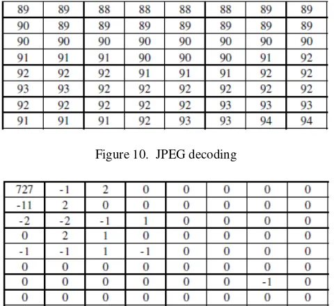
As shown in Figure 8 is the original image being interleaved into two sub-images using horizontal pixel interleaving approach. The vertical pixel interleavings are shown in Figure 9. In the next step, the sub-images are then divided into blocks of 8x8 matrixes and each block is transformed into frequency domain for quantization. Figure 10 shows a sample blocks original input and transformed into DCT domain where many of the values are converted into zeros or near zeros. This step has reduced the file size significantly due to this reason. Figure 11 shows the result of using same sub-image without dividing into blocks of 8x8 for 2D DCT. It shows clearly that the block-based method improves the compression ratio by using lesser bytes to represent the same data.
Lastly, Huffman entropy coding was utilized. As shown in Figure 12 are the original matrix and results after inverse transformation. It can be seen that there are high similarity between the 3 matrices in (a), (b) and (c) especially the top left elements of transformed coefficient. This is in-line with the earlier discussion on keeping the lower frequency components in 2D DCT
[image:7.612.190.430.142.362.2].
Figure 10. JPEG decoding
Figure 11. Transformed coefficient for block based DCT
Figure 12. Results after inverse transformed with masking (a) original matrix (b) results from Mask 8 (c) results from Mask 16.
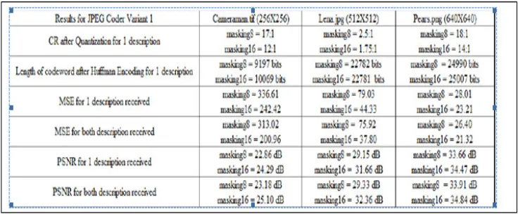
3.2. Performance Comparison
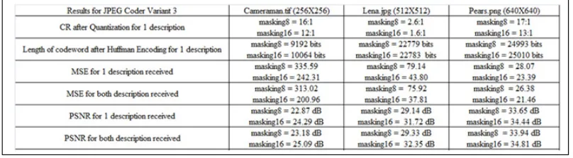
[image:7.612.192.427.404.541.2]differ significantly. The MSE for tif image is much higher than the other 2 types. The other observations to note is the MSE difference between 1 descriptor and 2 descriptors are no more than 10%. This shows that the approach is suitable for even low bandwidth transmission. The signal to noise ratio is better for png image. The use of 1 descriptor and 2 descriptors do not appear to be significant. Our approach achives a good PSNR. The CR can be improved through fine-tuning our quantizer. The experiment also shows that our technique has been getting good results with the use of png files compression. The file size could be shrinked down by 18 times without sacrificing PSNR.
Table 2 shows the results of JPEG HA coder using horizontal pixel interleaving and arithmetic encoding. This coder measures the quality of re-constructed image ranging from level 1 to 100. Level 1 gives the highest compression but lowest re-constructed quality. On the other hand, level 100 gives the lowest compression but highest quality. Hence we measures the bits needed for level 50 and 99. For level 50, the highest compression achieved is 33 times. On the other hand, the best quality level of 99 only obtained 5 times compression for the png image. The MSE for this model appear to be a lot larger than the previous model. The PSNR for all three types of images are lower than the previous model as well.
Table 3 shows the results of JPEG VH coder using vertical pixel interleaving and Huffman encoding. The compression ratio is quite similar to HH. From this table, the MSE for JPG and PNG images are lower and quite similar to JPEG HH decoder. This further suggests that the MSE for Huffman coding is much lower than Arithmetic coding. Table IV shows the results of JPEG VA coder using vertical pixel interleaving and Huffman encoding. With the use of vertical pixel interleaving and Huffman encoding, the results are similar to JPEG HA model, higher MSE and lower PSNR.
[image:8.612.125.493.538.690.2]The experimental results also show that the use of horizontal pixel interleaving and vertical pixel interleaving give similar results. The difference between the two is less than 1dB for PSNR. Both methods are recommended for 2D DCT system. The other observation is on the choice of quantizers. The compression ratio for type II quantizer (in use for JPEG HA and VA model) is around twice better than type I quantizer ( in use for JPEG HH and VH model), the PSNR achieved is around 1.5 times poorer. Type II quantizer compresses an image by dividing every 2D DCT coefficients by a constant. The low frequency area is affected and hence the quality of re-constructed image. Type I quantizer successfully keep lower frequency coefficients without affecting it.
TABLE 2. JPEG HA CODER RESULTS (Horizontal PI and Arithmetic Encoding)
TABLE 3. JPEG VH CODER RESULTS (Vertical PI and Huffman Encoding)
TABLE 4. JPEG VA CODER (Vertical PI and Arithmetic Encoding)
4.
C
ONCLUSIONsame size across the three types of images. Whereas for mean square error (MSE), the difference between using 1 descriptor and 2 descriptors do not differ significantly. The other observations to note is the MSE difference between 1 descriptor and 2 descriptors are no more than 10%. This shows that the approach is suitable for even low bandwidth transmission. The experimental results also show that the use of horizontal pixel interleaving and vertical pixel interleaving give similar results. The difference between the two is less than 1dB for PSNR. Both methods are recommended for 2D DCT system. The other observation is on the choice of quantizers. The compression ratio for type II quantizer (in use for JPEG HA and VA model) is around twice better than type I quantizer ( in use for JPEG HH and VH model), the PSNR achieved is around 1.5 times poorer. Type II quantizer compresses an image by dividing every 2D DCT coefficients by a constant. The low frequency area is affected and hence the quality of re-constructed image. Type I quantizer successfully keep lower frequency coefficients without affecting it.
R
EFERENCES[1] Andrew B. Watson,‘Image Compression Using the Discrete Cosine Transform’, Mathematica Journal Page(s): 81-88. 1994
[2] Subhasis Saha,‘Image Compression – from DCT to Wavelets: A Review’, Crossroads, 6(3), March 2000. Pp. 12-21.
[3] “A brief review of DCT-based JPEG and few novel wavelet-based image coding algorithms in ACM Crossroads”, http://www.acm.org/crossroads/xrds6-3/sahaimgcoding.html, access 27 Oct 2014. [4] Ahmed, N., Natarajan, T., & Rao, K. R. (1974),‘Discrete Cosine Transfom’, IEEE Transactions on
Computers, C-23(1), 90-93.
[5] Vaishampayan, V. A. (1993), ‘Design of multiple description scalar quantizers’, Information Theory, IEEE Transactions on, 39(3), 821-834.
[6] Anhong, W., Yao, Z., & Jeng-Shyang, P., ‘Multiple Description Image Coding Based on DSC and Pixel Interleaving’ Paper presented at the Intelligent Information Hiding and Multimedia Signal Processing, 2008. IIHMSP '08 International Conference on. 2008.
[7] Zixiang, X., Ramchandran, K., Orchard, M. T., & Ya-Qin, Z. (1999), ‘A comparative study of DCT- and wavelet-based image coding’, Circuits and Systems for Video Technology, IEEE Transactions on, 9(5), 692-695.’