Contents lists available atScienceDirect
Journal of the Mechanical Behavior of
Biomedical Materials
journal homepage:www.elsevier.com/locate/jmbbm
Representing the e
ff
ect of variation in soft tissue constraints in experimental
simulation of total knee replacements
Helena Johnston
a, Abdellatif Abdelgaied
a, Hemant Pandit
b, John Fisher
a, Louise M. Jennings
a,⁎aInstitute of Medical and Biological Engineering, University of Leeds, Leeds, UK
bLeeds Institute of Rheumatic and Musculoskeletal Medicine, Faculty of Medicine and Health, University of Leeds, Leeds, UK
A R T I C L E I N F O
Keywords:
Total knee replacement Wear
Soft tissues Kinematics Simulation
A B S T R A C T
As life expectancy and activity levels of patients increase so does the demand on total knee replacements (TKRs). Abnormal mechanics and wear of TKRs can lead to implant loosening and early failure. Polyethylene inserts of varying design and conformity have been introduced in the past decade to improve stability and patient's confidence in the replaced knee, particularly in cases where soft tissue support around the knee is sub optimal. This study experimentally investigated the effect of variation in the soft tissues on the kinematics and wear of a TKR on three different tibial insert designs. DePuy Sigmafixed bearing TKRs with moderately cross-linked UHMWPE and the ISO force control inputs were used. Different soft tissue constraints were simulated using virtual springs in an ISO force controlled simulation system. The spring gaps and stiffness' were varied and their effect on the output kinematics and wear rates assessed. The lower conformity inserts resulted in significantly higher displacements and more variation between the stations on the simulator. They were also more sensitive to changes in the soft tissue constraints than the high conformity insert. The wear rate for the high tension springs was significantly lower than for the lower tension springs tested. Tibial insert geometry and soft tissue con-straints significantly affected kinematics and wear in these experimental simulations. Soft tissue constraints and the variability in patients are important considerations in the stratified design of TKRs and approach to patient selection.
1. Introduction
From 2003 to 2015 over 800,000 primary total knee replacements (TKRs) were carried out in England, Wales and the Isle of Man (NJR, 2006). Wear is one of the main causes of failure in TKRs (Sharkey et al., 2002; Galvin et al., 2006; NJR, 2006). As life expectancy and activity levels increase, wear and early failure of TKRs could become more of an issue; demand is projected to increase in the USA by more than 600% by 2030 (Bayliss et al., 2017; Kurtz et al., 2007). The risk of revision also increases as the age at primary implantation decreases, with the lifetime risk of revision at 35% for patients aged 50–54 years (Bayliss et al., 2017). Experimental wear simulation has been used with dif-ferent methods and conditions to predict the wear performance of total joint replacements. In addition to patient and surgical factors the wear rates of a TKR has been shown to depend on a number of factors in-cluding insert material (bearing), component design, surface geometry, set up, contact area, stress and knee kinematics (Abdelgaied et al.,
2014; McEwen et al., 2005; Brockett et al.,2016). Therefore under-standing the factors that lead to abnormal mechanics and increased wear are vital in developing long lasting TKRs.
Currently the standard conditions for knee simulation are a walking cycle with an ideally aligned knee, representing an average patient. Experimental simulation may generate the average wear rates found in vivo. However it does not show the range of outcomes found in re-trievals (Grecu et al., 2016; Harman et al., 2001). This may be due to factors that are not currently replicated in standard knee simulation.
Different patient factors have been shown to affect the wear rate of TKRs; patient weight (Berend et al., 2008), the activities they perform, soft tissues and muscles (Moreland, 1988), the surgical alignment of the TKR (Moreland, 1988; Srivastava et al., 2012; Ezzet et al., 2004), and interactions between these factors, such as soft tissue and muscle me-chanics producing different kinematics for specific activities. Patient factors are outside the control of the operating surgeon. The aim of a TKR is to provide a stable knee which will function optimally and last
https://doi.org/10.1016/j.jmbbm.2018.07.011
Received 28 May 2018; Received in revised form 4 July 2018; Accepted 5 July 2018
Abbreviation:AP, Anterior-posterior; AF, Axial force; CI, Confidence interval; CR, Cruciate retaining; CS, Cruciate substituting; CVD, Curved tibial insert; FE, Flexion extension; MC, Million cycles; PLI, Partially lipped insert; TKR, Total knee replacement
⁎Corresponding author.
E-mail address:[email protected](L.M. Jennings).
Available online 10 July 2018
1751-6161/ © 2018 The Authors. Published by Elsevier Ltd. This is an open access article under the CC BY license (http://creativecommons.org/licenses/BY/4.0/).
joint and the applied simulated soft tissue constraints. Both methods of simulation have their place, the choice between them depends on the research question. Force control results in more variation in the mo-tions occurring between the stamo-tions on the simulator, as small diff er-ences such as component position or friction will affect the kinematics. In a study where the aim is to test predefined kinematics, for example to test a particular action such as walking up stairs, displacement control would be the better option. Conversely under force control the motion of the knee can change in response to the applied loads, soft tissue constraints, insert design, changes in the material deformation and wear scar. For tests where the kinematics are not known, for example under different soft tissue conditions, force control would be used. However it must be recognised that in defining specific soft tissue constraints as an input in the force control situation, the kinematic output is being indirectly controlled. There are ISO (Standard, 2009, 2014) standard TKR test conditions for both force and displacement control simulation. These define test conditions such as the input pro-files and methodology.
Under force control simulation springs are used to replicate the ef-fect of all the soft tissues within the natural knee, including the ACL and PCL. The ISO standard (Standard, 2009) AP and TR springs have a gap around the zero position to replicate the soft tissues within the knee as they are not linearly elastic (Fukubayashi et al., 1982; Kanamori et al., 2002). The size of this spring gap reflects the soft tissue laxity within the knee. The ISO standard for a cruciate retaining (CR) prosthesis has an AP spring with a gap of ± 2.5 mm and a linear restraint stiffness of 9.3 N/mm and 44 N/mm for anterior and posterior motion respectively. The ISO TR spring has a gap of ± 6° and a rotational restraint stiffness of 0.36 Nm/° (Standard, 2009). For a cruciate substituting (CS) pros-thesis the same AP and TR spring gaps are applied with a linear re-straint stiffness of 9.3 N/mm in both directions and a rotational re-straint stiffness of 0.13 Nm/°.
As the tension of the tissues within the knee vary between patients the spring gap and stiffness are difficult to choose. Ligament balance during surgery is a subjective process so can lead to unbalanced knees (Griffin et al., 2000; Babazadeh et al., 2009). Ligament balancing has been found to be an important factor in wear, range of motion, and pain (Babazadeh et al., 2009). The ligament balance affects the mechanics of the knee, how it moves and the resulting variation in performance and wear in individual patients.
Just as soft tissue tension and laxity influences joint kinematics in the natural knee, similarly soft tissue constraints, spring stiffness and spring gap will influence resultant kinematics in the force control knee simulator. The aim of this study was to experimentally investigate the effects of variation in the soft tissue constraints on the output kine-matics and wear of TKR with different tibial insert geometries. A sys-tematic investigation was carried out to address the following research questions about the effect on output kinematics and wear:
Output kinematics:
1. What effect does the tibial insert geometry have on the kinematics? 2. What effect does the laxity of the knee, represented by the simulator
Wear:
4. What effect does the ligament stiffness have on the wear rate of the TKR?
2. Materials and methods
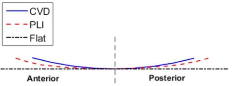
All the investigations were carried out using DePuy Sigmafixed bearing TKR components (DePuy Synthes, UK). The tibial inserts were moderately crosslinked ultra-high molecular weight polyethylene (UHMWPE) (5MRad irradiated and re-melted GUR1020). Three dif-ferent tibial insert designs were tested; curved (CVD), partially lipped (PLI), and customflat inserts (Fig. 1). The CVD inserts are used clini-cally so were used as standard for all tests with the PLI inserts also used for the spring gap and tension tests. All three insert designs were tested under standard ISO (Standard, 2009) test conditions.
This experimental study was carried out using a new generation electro-mechanical six station ProSim knee simulator. The simulator hasfive fully independently controlled axes and can be run in either force control or displacement control. The electro-mechanical simula-tors provide better kinematic control (outputs following the demand inputs more closely) than the first generation pneumatic simulators (Abdelgaied et al., 2017). The lubricant used was 25% bovine serum with 0.04% sodium azide solution. The AP and TR displacements are defined in terms of the tibial insert; anterior displacement is anterior displacement of the tibial component. The axial force (AF) is applied on the femoral component and the flexion-extension (FE) is defined in terms of the femoral component.
For this study force control was used as this allowed the kinematics in each test to be determined as an output of the study, enabling the effect of the soft tissue constraints and insert design on the kinematics to be studied. Virtual springs were used within the simulator in order to represent the effects of soft tissues within the knee. The use of virtual springs allowed any response profile to be used for the springs. The desired spring profile for the AP and TR springs was uploaded into the simulator. This defined the force to be applied for a given displacement. During the cycle the displacement in the previous step was used to determine the spring force that should be applied in the next step. The applied force constrained the motion, replicating the effect of the soft tissues in the knee. The virtual springs within the simulator were va-lidated experimentally by applying either an AP force or a TR torque and measuring the resulting displacements.
The ISO (Standard, 2009) force input profiles were used (Fig. 2), with the AF varying between 268 N and 2600 N, the FE between 0° and 60°, the AP force between -111 N and 265 N and the TR torque from −1 Nm to 5.9 Nm. The centre of rotation of the femoral component was set in accordance with the ISO standard (Standard, 2009) including the medial-lateral offset. One set of components was used for all the kinematic tests, this was to remove any effect due to differences in the components such as thefixture weight or position.
[image:2.595.318.552.55.142.2]constraints as they have previously been shown to affect the wear rate of the TKR (McEwen et al., 2005). Each test was carried out on all six stations of the simulator with 100 consecutive cycles being recorded on each station. The output kinematics for these cycles were then averaged across all the stations and the data is presented with 95% confidence interval (CI).
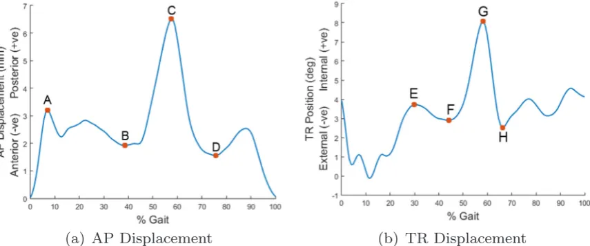
In order to compare the output kinematics from each test minimum and maximum values at defined points throughout the gait cycle were assessed in order to characterize the profiles (Fig. 3). For the AP dis-placement points A through to D were defined as the maximum from 0% to 20% gait, the minimum from 20% to 50% gait, the maximum from 50% to 70% gait and the minimum from 70% to 90% gait re-spectively. For the TR position points E through to H were defined as the maximum from 20% to 40% gait, the minimum from 40% to 50% gait, the maximum from 50% to 65% gait and the minimum from 65% to 80% gait.
The values of these points were then compared using a one way ANOVA with significance taken atp<0.05using IBM SSPS Statistics 22. A post hoc Tukey' s test was used to compare the outputs of more than two groups with significance taken atp<0.05.
2.1. What effect does the tibial insert geometry have on the kinematics?
To compare the kinematic outputs with different tibial insert de-signs each of the three inserts were tested with the ISO standard (Standard, 2009) CR springs used (Research question 1 inTable 1).
2.2. What effect does the laxity of the knee, represented by the simulator AP and TR spring gaps, have on the output kinematics?
To determine the effect of the spring gaps on the output kinematics, the gap values were varied; for the AP spring the gap was varied from 0 to 9 mm in 1 mm increments, with the ISO spring gap of 2.5 mm being used instead of 2 mm. The TR spring gap was varied from 0 to 11° at 1° intervals (Research question 2 inTable 1). Only one spring was varied at a time with the other kept at the ISO standard (Standard, 2009) value (AP spring gap 2.5 mm and TR spring gap 6°). The ISO CR spring ten-sions were used for both the AP and TR springs. The different tests were compared to the output kinematics using the ISO standard (Standard, 2009) spring gaps. This was carried out on both the CVD and PLI inserts to investigate the relationship between the spring gaps and the tibial inserts.
2.3. What effect does the ligament stiffness, represented by the simulator AP and TR spring tensions, have on the output kinematics?
[image:3.595.84.513.55.238.2]To test the effect of the spring tensions on the output kinematics the AP spring tension was tested at 0, 20, 44, 60, 80, 100, 150, 200 and 250 N/mm (Research question 3 inTable 1). The TR spring was tested at 0, 0.1, 0.36, 0.5, 0.8 and 1 Nm/°. Only one was changed at a time with the other kept at the ISO standard value (44 N/mm and 0.36 Nm/° ). The different tests were compared to the output kinematics using the ISO standard (Standard, 2009) spring tensions. This test was carried out Fig. 2.Input AP force and TR torque profiles (Standard, 2009).
[image:3.595.85.513.550.728.2]using the CVD and PLI inserts to find the relationship between the spring tensions and the insert design.
2.4. What effect does the ligament stiffness have on the wear rate of the TKR?
To investigate the effect of the soft tissue constraints on the wear rates three wear tests were each run for 2 million cycles (MC) using the CVD insert. Each test used the ISO (Standard, 2009) force control standard conditions including input profiles.
The first test used the ISO standard CR spring constraints to re-present a knee with a resected ACL (Standard, 2009). The second test was designed to represent a patient with damaged ligaments; the ISO CS springs were used in order to represent a knee with a damaged PCL.
The third test represented a patient with a stiffknee; spring tension values were chosen using previous clinical data. A previous study (Warren et al., 1994) found the average posterior displacement under a 100 N posterior load was 1.84 ± 1.05 mm. Taking the lower value one standard deviation from the mean in order to represent a patient with a stiffer than average knee, and assuming there is no laxity within the knee, this gives an AP spring tension of 127 N/mm. A previous study into the rotation of the knee under 10 Nm internal torque found that the
fi
was carried out on each set of wear results to determine whether there was a significant difference.
The data associated with this paper is openly available through the University of Leeds Data Repository (https://doi.org/10.5518/391).
3. Results
3.1. What effect does the tibial insert geometry have on the kinematics?
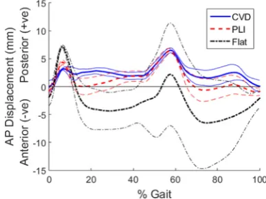
Figs. 4 and 5show the effect of tibial geometry on the output AP and TR displacements respectively. Three insert designs were tested; CVD, PLI andflat. Each of the tibial insert designs resulted in a similar AP profile shape with peaks at 7% and 60% gait (Fig. 4).
The lower conformity inserts, particularly theflat insert, resulted in more anterior displacement. However there was also much more var-iation with theflat insert, resulting in a 95% CI of 9 mm at 60% gait. The PLI andflat inserts had higher peaks at 7% gait compared to the CVD insert; 7 mm, 4.4 mm and 3 mm in the posterior direction for the flat, PLI and CVD inserts respectively. At this point (A inFig. 3) there was a significant difference between all three inserts (p= <0.01). At point B there was a significant difference between theflat and other two inserts (p<0.01) and at point D between the flat and CVD insert (p = 0.019).
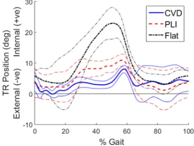
The insert design had a large effect on the TR position profile shape and amplitude however the displacement remained in the internal di-rection for all designs (Fig. 5). The lower the conformity of the insert the higher the peak TR position and the earlier in the cycle this peak occurred. For thefirst half of the cycle there was a significant difference between all three inserts (p<0.01). Theflat insert had a peak of 23° at 50% gait which followed the profile shape of the TR torque profile (Fig. 2) more closely than the PLI or CVD inserts, as the peak was larger and occurred earlier in the cycle. The PLI and CVD inserts had peaks of 10.9° and 8° at 57% and 58% gait respectively. At this point (point G in Fig. 3) there was a significant difference between theflat insert and the 3
2.5 1 0
44 2.5 0.36 11
10 9 8 7 6 5 4 3 2 1 0
3 CVD &
PLI
250 2.5 0.36 6
200 150 100 80 60 44 20 0
44 2.5 1 6
0.8 0.5 0.36 0.1 0
[image:4.595.39.291.80.494.2] [image:4.595.333.527.574.719.2]CVD and PLI inserts (p<0.01).
3.2. What effect does the laxity of the knee, represented by the simulator AP and TR spring gaps, have on the output kinematics?
The AP and TR spring gaps were varied tofind the effect on the output kinematics. The AP gap was tested from 0 to 9 mm; the higher the AP gap the higher the AP displacement. This occurred throughout the cycle but particularly at the peak at 60% gait. For the CVD and PLI inserts there was a linear relationship between the peak AP displace-ment and the AP spring gap. The spring gap change had more of an effect on the PLI insert than the CVD insert; the gradient of the trend line for the PLI insert was significantly higher than for the CVD insert (p = 0.017).
The TR spring gap was tested at 0–11° with 1° intervals. As with the AP spring the higher the TR gap the higher the TR displacement throughout the cycle. The relationship of TR spring gap to TR dis-placement had a similar linear trend on both the CVD and PLI inserts with the displacement increasing as the spring gaps increased; the gap increase from 0° to 11° resulted in an increase in the peak TR position of 4.5° and 4.7° for the CVD and PLI inserts respectively. The PLI insert had an offset of around 2° higher TR position throughout the test compared to the CVD insert. There was no significant difference be-tween the gradients of the trend lines but the y-intercept was sig-nificantly higher on the PLI insert (p = 0.033).
Changing the spring gaps did not affect the shape of the output profiles; it affected their magnitude and peak values. After these tests the spring gaps were kept at the ISO values of 2.5 mm and 6°.
3.3. What effect does the ligament stiffness, represented by the simulator AP and TR spring tensions have on the output kinematics?
The AP spring tension was tested at 0, 20, 44, 60, 80, 100, 150, 200 and 250 N/mm. This affected the magnitude of the AP displacement throughout the cycle but particularly from 50% gait onwards. The re-lationship between the peak AP displacement and the AP spring tension is shown inFig. 6for the CVD and PLI inserts.
There was a similar trend with both insert designs; as the spring tension increased the peak displacement decreased plateauing after 150 N/mm at around 4 mm. Increasing the spring tension also reduced the minimum at 75% gait (point D in Figure [fi g:Maximum-and-minimumPoints]). It followed a similar trend to the peak displacement; plateauing after 150 N/mm. Varying the AP spring tension had a minimal effect on the TR position; the only difference occurred at 60–80% gait where a higher AP spring tension resulted in a more gradual decrease in the TR position from the peak at 60% gait.
The TR spring tensions were tested at 0, 0.1, 0.36, 0.5, 0.8 and 1 Nm/°. As with the AP springs this did not change the profile shape,
however they changed the amplitude of the output profile. The higher the spring tension the lower the TR position throughout the cycle. On the PLI insert the different spring tensions had more of an effect on the peak TR position; there was a larger range of 4.9° compared to 1.6° for the CVD insert from 0N/° to 1 Nm/° (Fig. 7).
3.4. What effect does the ligament stiffness have on the wear rate of the TKR?
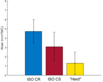
Three wear tests were run for 2MC with the CVD inserts and three spring tensions; ISO CR springs, ISO CS springs and “hard” springs based on clinical data for a stiffknee.
The different ligament stiffness's resulted in a significantly different peak AP displacements with the CS springs having an average of 6.75 mm compared to 5.5 mm and 2.3 mm with the CR and“hard” springs respectively (p<0.01) (Fig. 8). The ligament stiffness' also re-sulted in a significantly different peak TR displacements of 9.23° compared to 7.91° and 3.33° with the CS, CR and“hard” springs re-spectively (p<0.01) (Fig. 9).
[image:5.595.324.541.56.221.2]With the CS springs three stations had significantly different kine-matics to the other three stations of the simulator; this occurred at points A-C in the AP displacement profile. At point C three stations had a significantly higher displacement of 7.5 mm compared to 6 mm on the other stations (p<0.01). There was no significant difference between the sum of the displacements in either the AP or TR profiles across the whole cycle (p>0.6).
[image:5.595.65.259.58.203.2]Fig. 5.Effect of insert design on TR positions with the 95% confidence intervals shown by lighter lines.
Fig. 6.Relationship between the AP displacement and the AP spring tension for the CVD and PLI inserts.
[image:5.595.322.543.549.717.2]After 2MC the average wear rates were 4.71 ± 1.29 mm3 /MC, 3.06 ± 1.57 mm3/MC and 1.58 ± 1.20 mm3/MC for the CR, CS and “hard”springs respectively (Fig. 10). There was no significant diff er-ence between the wear values for the CS and CR springs (p = 0.064) or between the CS and “hard” springs (p = 0.076). However due to the
– –
inflexion across 77 TKR patients (Asano et al., 2004). This study in-vestigated the effect of soft tissue constraints on the kinematics and wear of TKRs using experimental simulation.
The use of force control for this study allowed the different soft tissue constraints, represented by the springs, to control the output kinematics of the joint. Differences between each station in the simu-lator, such as internal friction, affected the output kinematics especially when lower spring tensions were used. In order to reduce these dif-ferences the same component was used on each station and 100 cycles were recorded on each station. This removed offsets in the output AP and TR displacements across the stations. For the AP displacement this offset was up to 3 mm and up to 4° on the TR position. The output kinematics from the tests gave an indication of the stability of the knee. Wear tests were then carried out using three spring tensions tofind the effect of the soft tissue tension on the wear rate.
The ISO standard (Standard, 2009) force control input profiles are intended to mimic the muscle and joint forces that occur during walking, while the spring tensions and gaps represent the restraint and laxity of the soft tissues. These ISO standard test conditions represent an average patient, with ideal alignment, and does not simulate a range of patient groups.
Previous studies have investigated the laxity and ligament tensions of the knee in TKR patients (Warren et al., 1994) or cadaveric speci-mens (Musahl et al., 2007; Kanamori et al., 2002; Fukubayashi et al., 1982). Due to the variation in ligament stiffness and laxity between patients there is a range of results. The AP displacement under a given load also depends on the flexion position of the knee (Fukubayashi et al., 1982). Under 100 N posterior load the displacement of the knee was found to be around 2.5–2.8 mm for TKR patients at 15–20°flexion (Warren et al., 1994). Under the same load another study found pos-terior displacements of 4 mm and 10 mm at 0°flexion for an intact knee and a knee with no PCL respectively (Fukubayashi et al., 1982). For an intact knee the posterior displacement under 100 N was found to be relatively constant across differentflexion positions. However with the PCL removed the posterior displacement varied from around 9–18 mm from 0 to 90°flexion (Fukubayashi et al., 1982).
As with the AP tension there is variation in the rotational stiffness of the knee. Previous studies have applied a TR torque to cadaveric spe-cimens and measured the rotation. One study applied a TR torque of 6 Nm and found rotation of around 10° and 20° for 0° and 90°flexion respectively (Musahl et al., 2007). Another study found that the re-sponse under a range of applied TR torques was approximately linear within 10° of the zero position, with tension values of around 0.34 Nm/° and 0.3 Nm/° for an intact and ACL resected knee (Kanamori et al., 2002).
[image:6.595.55.273.58.222.2]Three different tibial insert designs were tested tofind the effect of the tibial insert design on the output kinematics. The design of the tibial insert particularly affected the TR position. A lower conformity insert had a higher peak position which occurred earlier in the cycle. This was due to the lower conformity inserts allowing the TR position to follow the shape of the TR torque profile more closely. The lower conformity inserts also resulted in more anterior AP displacement.
[image:6.595.55.273.264.429.2]Fig. 8.Average AP displacement with the ISO CR, ISO CS and“hard”springs with the CVD insert.
Fig. 9.Average TR displacements with the ISO CR, ISO CS and“hard”springs with the CVD insert.
[image:6.595.54.274.469.643.2]The effect of the laxity, represented by the spring gaps, and soft tissue tensions, represented by the spring tensions, within the knee were investigated. The spring gaps and tensions affected the peak dis-placements in both the AP and TR positions, particularly in the second half of the cycle. This was due to the AF decreasing to its minimum from 50% gait, the friction from the applied AF in thefirst half of the cycle restricted the AP displacement.
The increased spring gaps resulted in a linear relationship with the peak AP and TR displacements on both the CVD and PLI inserts. Changing the AP spring gap had more of an effect on the PLI insert; this may be due to the high conformity of the CVD insert restricting the motion. However changing the TR spring gap resulted in a similar re-sponse on both inserts, with the only difference being that the PLI insert had 2° more rotation across all the tests.
Increasing the AP spring tension reduced the peak AP motion on both the CVD and PLI inserts. The peak AP displacement plateaued at around 4 mm from 150 N/mm onwards. This may be due to the spring gap of 2.5 mm; as the spring tension increased and the peak AP de-creased the springs were only applied over a short section of the gait cycle. Therefore the difference in spring tension had less of an effect. The TR spring tension had very little effect on the CVD insert; the conformity of the insert may be restricting the TR motion so that the effect of the spring was minimal. However with the PLI insert the peak TR position decreased as the tension increased. Further testing with tensions higher than 1 Nm/° may show the same plateau as with the AP spring; the data collected showed a trend line that started to plateau at around 9°.
The different spring tensions resulted in significantly different output kinematics. The looser ISO CS spring also resulted in more variation in the kinematics between stations on the simulator. Due to the increased variation there was no significant difference in wear rate between the CS springs and the other two spring conditions. However the“hard”springs did result in a significantly lower wear rate than the ISO CR springs.
A previous study (Haider et al., 2006) investigated the effect of different spring tensions and gaps on the output kinematics under force control. A four station Instron-Stanmore knee simulator with DePuy PFC Sigma Fixed bearing knee components were used. Two springs were attached to the simulator to restrain the AP motion, they were separated by 47 mm and therefore also applied restraint to the TR motion. High tension springs (anterior restraint of 7.24 N/mm and posterior restraint of 33.8 N/mm) were tested with a 2.5 mm and 0 mm gap. Both high and low tension springs (anterior and posterior restraint of 7.24 N/mm) with a 2.5 mm gap were used to investigate the effect of spring tension.
The spring gap tests had similar results to this study; there was no significant difference between this study and the previous study for the peak AP displacements for any of the springs tested (p>0.1). The low tension spring resulted in a similar kinematic profile but with a higher amplitude. For the low tension TR springs the maximum TR position in the previous study was significantly higher than that found in this study (17° compared to 8° ) (p = 0.014). This may have been due to the offset between the sets of results of around 6°. However there was no sig-nificant difference between the previous study and this study' s peak TR displacement for a high tension spring with a 0 mm or 2.5 mm gap (p>0.1).
Differences in the results between studies may be due to differences in the test conditions. For example this study used virtual springs rather than the two physical springs used previously to apply both AP and TR restraint. Different knee simulators have also been used; this study used a ProSim simulator compared to the Instron-Stanmore simulator used in the previous study. The Instron-Stanmore simulator is pneumatic (Walker et al., 1997) compared to the electro-mechanical simulator used for this study. Electro-mechanical simulators can provide better kinematic following than the first generation pneumatic simulators (Abdelgaied et al., 2017).
The weight of the tibialfixtures were also found to affect the output kinematics, especially that of the AP displacement. The heavier the ti-bialfixture the lower the AP displacement. Differences in the tibial fixture weights between any tests could result in differences in the re-sults and is an important consideration. This could also be a cause for differences in this test and the previous study.
The soft tissue response in the knee varies between patients (Asano et al., 2004; Kanamori et al., 2002). The choice of these restraint values is an important factor for the kinematics and wear. When choosing the values for a test a specific patient group should be chosen. For a patient with an unstable knee due to the soft tissue tensions a high conformity insert would be used. Therefore, when choosing test conditions, the insert design and the soft tissue constraints should be matched so that they are clinically relevant. There are also other patient factors such as patient body mass index (BMI) and component position that may affect the kinematics but have not been investigated in this study.
There are some limitations to this study, firstly there was some variation between the stations of the simulator, particularly when the low tension springs were applied. The high variation meant that dif-ferences between tests were less clear. This study also only investigated the effect of the tibial insert surface geometry, further testing would investigate the effect of component design more thoroughly, for ex-ample the effect of different femoral designs. Although the impact on wear and kinematics has been examined, it is possible that there is a significant impact on forces going through implant-cement or cement-bone interface with varying restraints introduced by changes in liga-ment tension as well as surface geometry of the insert. These can manifest in a stable knee in the short-term but with a high risk of im-plant loosening in the mid to long-term. In this study we could not measure the magnitude of forces (shear in particular) going through these interfaces and therefore cannot comment upon the associated risk of implant loosening.
5. Conclusions and further work
Soft tissue constraints had a significant effect on the kinematics of the TKRs of varying geometries tested in this study. Simulating the average soft tissue tensions will not represent the variation across dif-ferent patients. Patient variation should be represented in experimental simulation; in order to simulate a patient with increased laxity in the knee an increased spring gap should be used. The difference in spring tensions were found to have a lower effect on the high conformity tibial inserts. To ensure a test is clinically relevant the spring conditions should be considered with the tibial insert design in mind. For example a low conformity insert would not be used in a patient with high laxity. In order to replicate the range of outcomes that occur in vivo, experi-mental simulation must include a range of patient factors such as dif-ferent soft tissue constraints. Further work will include investigation into the effects of surgical and component alignment for different soft tissue conditions on the output kinematics and wear of TKRs.
Acknowledgments
This research work was supported by EPSRC, University of Leeds Alumni Fund and MeDe. JF is an NIHR Senior Investigator and sup-ported as director of The EPSRC Center of Innovative Manufacturing in Medical Devices. This research work was also supported by DePuy Synthes, UK, who supplied the components studied. Thank you to the laboratory technicians in IMBE for their help with the experimental testing.
References
2016. The influence of simulator input conditions on the wear of total knee re-placements: an experimental and computational study. Proc. Inst. Mech. Eng. Part H: J. Eng. Med. 230, 429–439.
Ezzet, K., Hermida, J., Colwell Jr, C., D'Lima, D., 2004. Oxidized zirconium femoral components reduce polyethylene wear in a knee wear simulator. Clin. Orthop. Relat. Res. 428, 120–124.
Fukubayashi, T., Torzilli, P., Sherman, M., Warren, R., 1982. An in vitro biomechanical evaluation of anterior-posterior motion of the knee. J. Bone Jt. Surg. 64-A, 258–264.
Galvin, A., Kang, L., Tipper, J., Stone, M., Ingham, E., Jin, Z., Fisher, J., 2006. Wear of crosslinked polyethylene under different tribological conditions. J. Mater. Sci.: Mater. Med. 17, 235–243.
Grecu, D., Antoniac, I., Trante, O., Niculescu, M., Lupescu, O., 2016. Failure analysis of retrieved polyethylene insert in total knee replacement. Biomaterials 6, 12–15.
Griffin, F., Insall, J., Scuderi, G., 2000. Accuracy of soft tissue balancing in total knee arthroplasty. J. Arthroplast. 15, 970–973.
Haider, H., Walker, P., DesJardins, J., Blunn, G., 2006. Effects of patient and surgical alignment variables on kinematics in tkr simulation under force-control. J. ASTM Int. 3 (10), 3–16.
man: 13th annual report.
Sharkey, P., Hozack, W., Rothman, R., Shastri, S., Jacoby, S., 2002. Why are total knee arthroplasties failing today? Clin. Orthop. Relat. Res. 404, 7–13.
Srivastava, A., Lee, G., Steklov, N., Colwell Jr., C., Ezzet, K., D'Lima, D., 2012. Effect of tibial component varus on wear in total knee arthroplasty. Knee 19 (5), 560–563.
Standard, B., 2009. Implants for Surgery - Wear of Total Knee Joint Prostheses, Part 1: Loading and Displacement Parameters for Wear Testing Machines with Load Control and Corresponding Environmental Conditions for Test. 14243-1.
Standard, B., 2014. Implants for Surgery - Wear of Total Knee Joint Prostheses, Part 3: Loading and Displacement Parameters for Wear Testing Machines with Displacement Control and Corresponding Environmental Conditions for Test. 14243-3.
Walker, P., Blunn, G., Broome, D., Perry, J., Watkins, A., Sathasivam, S., Dewar, M., Paul, J., 1997. A knee simulating machine for performance evaluation of total knee re-placements. J. Biomech. 30, 83–89.