This is a repository copy of Metastable monotectic phase separation in Co–Cu alloys. White Rose Research Online URL for this paper:
http://eprints.whiterose.ac.uk/131410/ Version: Accepted Version
Article:
Jegede, OE, Cochrane, RF and Mullis, AM (2018) Metastable monotectic phase
separation in Co–Cu alloys. Journal of Materials Science, 53 (16). pp. 11749-11764. ISSN 0022-2461
https://doi.org/10.1007/s10853-018-2417-y
(c) Springer Science+Business Media, LLC, part of Springer Nature 2018. This is a post-peer-review, pre-copyedit version of an article published in Journal of Materials Science. The final authenticated version is available online at:
https://doi.org/10.1007/s10853-018-2417-y.
eprints@whiterose.ac.uk https://eprints.whiterose.ac.uk/ Reuse
Items deposited in White Rose Research Online are protected by copyright, with all rights reserved unless indicated otherwise. They may be downloaded and/or printed for private study, or other acts as permitted by national copyright laws. The publisher or other rights holders may allow further reproduction and re-use of the full text version. This is indicated by the licence information on the White Rose Research Online record for the item.
Takedown
If you consider content in White Rose Research Online to be in breach of UK law, please notify us by
1
Metastable monotectic phase separation in Co
–
Cu alloys
Oluwatoyin E. Jegede1*, Robert F. Cochrane1 and Andrew M. Mullis11School of Chemical & Process Engineering, University of Leeds, Leeds LS2 9JT, UK.
Email: pmoej@leeds.ac.uk (Jegede), R.F.Cochrane@leeds.ac.uk (Cochrane), A.M.Mullis@leeds.ac.uk (Mullis)
ORCID iD: https://orcid.org/0000-0001-6403-0637 https://orcid.org/0000-0001-5812-5226
https://orcid.org/0000-0002-5215-9959
Abstract
The liquid phase separation behaviour of metastable monotectic Co – Cu alloys was investigated as a function of cooling rate using a 6.5 m drop tube facility. A range of liquid phase separated morphologies were observed including stable two-layer core-shell, evolving core-shell and dendritic structures. It was found that in the core-shell structures the core was always the higher melting point (Co-rich) phase, irrespective of the core and shell volume fraction. In Cu-50 at. % Co alloy, high cooling rates were observed to yield two episodes of liquid phase separation, corresponding to binodal, followed by spinodal decomposition. The resulting structure comprised a core-shell structure in which the Co-rich core contained a very fine dispersion of Cu-rich particles with a Cu-rich shell which may, or may not, contain a similar dispersion of Co-rich particles.
Keywords: Co – Cu immiscible alloys
Core-shell microstructure
Liquid phase separation
Drop tube
Rapid solidification
*Address correspondence to Email: pmoej@leeds.ac.uk, jegedeoluwatoyin@yahoo.com
2 1 Introduction
During the processing of immiscible alloys under microgravity conditions a type of structure,
known as core-shell structures, may be formed in which droplets of a minor phase (which
coalesce to form the core) are enclosed in the liquid matrix of the majority phase (the shell)
[1]. There has been heightened interest in these structures, especially in monotectic alloys, due
to the possibility of fabricating heterogeneous functional particles with a combination of core
and shell materials in which both the size and composition can be engineered [2]. A significant
literature has developed related to core-shell structures in polymeric and metal oxide systems
[3], although metallic monotectic systems have been much less studied. Figure 1 is a schematic
representation of potential core-shell configurations identified in binary systems.
Figure 1: Different core-shell structure configurations likely in a binary monotectic system, (a) spherical core-shell [4], (b) core-shell particle with multiple cores, (c) multiple shell /matryoshka / onion like core-shell particle [5], (d) core-shell particle with embedded multiple spherical particles in the shell, (e) core-shell particle with inclusions in the core and (f) core-shell particle with embedded multiple spherical particles in both the core and shell [6].
The strong interplay of interfacial energy with temperature and/or composition gradients in
immiscible alloys leads to Marangoni convection which, in the microgravity environment, has
been used to explain the formation mechanism of core-shell structures [1,4,6–13]. In such an
environment, for instance during free fall, a temperature gradient between the surface and
centre of the falling droplet may be developed. If droplets of a metastable monotectic alloy are
cooled into the miscibility gap spherical particles of, what is generally reported in the literature
[image:3.595.84.418.301.508.2]3
droplets. The temperature gradient causes Marangoni motion, leading to the migration of these
minority phase particles towards the centre of the parent droplet where the temperature is
higher [1]. The migrating particles eventually coalesce by collision to form the core.
It is important to state that although Marangoni motion offers a basic explanation for the
formation of core-shell structures, it does not fully account for the whole range of solidification
features observed in metastable immiscible alloys. Possible contributions of other factors such
as composition, cooling rates, degree of undercooling, coalescence dynamics and volume
fraction of phases are still not fully explored [2].
N. Wang et al. [14] and C.P. Wang et al. [15] studied phase selection characteristics of
core-shell microstructures in two stable immiscible systems. They observed that in Fe-Sn and
Cu-Pb alloys, the surface energy of the phases was crucial in determining which phase forms the
core and which the shell. The surface energy was also critical in determining whether a double
or triple layer core-shell structure was formed. They reasoned that the phase with the lower
volume fraction also has the lower surface energy and, as such, spreads to the periphery of the
parent droplet thus forming an outer shell. They were of the opinion that if the reverse were the
case (minority phase having higher surface energy), the particles of the minority phase would
fail to spread even though a thermal gradient exists. The resulting structure would not therefore
be of the core-shell type, rather being one in which particles of the minority phase are randomly
dispersed within a majority phase matrix. This argument may also favour the formation of
matryoshka type core-shell structures (Figure 1c). Upon attaining a critical size Marangoni
convection will begin to transport the minority phase towards the centre of the droplet,
depleting the immediate surrounding liquid of this phase, thus resulting in a structure in which
the core is the same phase as the outermost shell, should this be retained. According to [14],
the migration capability of particles is dependent on the cooling rate and miscibility gap
temperature interval. However, in a ternary stable miscibility gap system, Ohnuma et al. [16]
observed that (Ni, Cu) - rich core was always surrounded by a Ag – rich shell even though the
Ag – rich phase had the lower volume fraction.
In the metastable Cu-Fe system, C.P. Wang and co–workers maintained that even though the
minority phase formed the core, there were instances where this was not the case [15]. Dai et
al. [4,17] also reported that in Al-Bi alloy system, Al always formed the core even when the
4
Additions to binary immiscible alloy systems have also been reported to have an effect on the
volume fraction of phases present. The addition of Ni to the Co-Cu system was reported to
significantly decrease the volume fraction of cobalt rich droplets [18]. However, in Cu-Sn-Bi
[13] the addition of the rare earth metal Ce was only found to have an effect on the Marangoni
velocity, with no link to the volume fraction of the phases being observed. Cooling rate has
also been reported to have an effect on Marangoni velocity [4,17], with core-shell
microstructures being readily formed at high cooling rates in Al-Si-Zr alloys [19].
N. Wang et al. [6] and C.P. Wang et al. [15], Dai et al. [7], Ma et al. [8] and Li et al. [13]
studied the effects of alloy composition on the formation of core-shell microstructures. N.
Wang et al. in a range of drop-tube experiments, discovered that migration period in monotectic
alloys was composition dependent [6]. The further the alloy was from the critical composition,
the shorter the migration window. Hence, core-shell microstructures were said to be readily
formed at compositions near the critical point, since they have a longer window for migration
to occur and thereby sufficient time for core formation by coalescence of migrating droplets.
This compositional effect was largely attributed to changes in the phase separation
characteristics. Variation in the nominal alloy composition will lead to changes in the volume
fraction and composition of the separated phases. This change in composition of the minority
phase will in turn lead to changes in the Marangoni velocity, migration period and consequently
the prospects of forming core-shell microstructures. Migration period was also found to be
dependent upon particle size, smaller particles displaying higher cooling rate and therefore
shorter migration periods. Hence, core-shell structures were less easily formed as particle size
was reduced [6].
Models have also been used by a number of researchers to simulate the formation of core-shell
microstructures [1,5,6,11,19–23]. Xu et al. [19] and K. Wang et al. [22] used mathematical
models to calculate the formation of the shell in Al-Si-Zr and Al-Ti-B-Re grain refiner alloys
respectively. Both models were based on the diffusion kinetics of the core-shell structure but
were dissimilar in that K. Wang et al. [22] assumed continuous diffusion in their model while
Xu et al. made no such assumption and were able to link the formation rate of the shell to the
cooling rate. Phase field simulation has also been used to study core-shell microstructure
formation [1,11,23]. In the work carried out by Shi et al. [1] on gas atomised Cu-Fe alloy, the
inter dependency of factors affecting formation and characteristics of core-shell
microstructures were highlighted. A spherical core was said to be centrally located in the
5
motion while an offset core was said to be the result of diffusion alone or phase separation with
fluid flow. Timing for the formation of the structure was also said to be influenced by the
processes at play; phase separation coupled with Marangoni motion was said to have faster rate
of coalescence [1].
The metastable Co-Cu system has been extensively researched using various methods, with
phase separation being found to occur in the alloy when undercooled beyond a certain level,
which is composition dependent [24–31]. The boundary of the miscibility gap has been
proposed in numerous studies [24–28]. Direct measurement of the liquid separation and
liquidus temperatures in undercooled Co-Cu alloys of composition ranging from Cu-16 at.%
Co to Cu-87.2 at.% Co was undertaken by Cao et al. [26] using differential thermal analysis
and glass fluxing. They reported that the directly determined miscibility gap was symmetrical
around 53 at. % Co and that the binodal temperature was 1547K, 108K below the observed
liquidus temperature.
The effect of undercooling on Co-Cu alloys has also been studied using electromagnetic
levitation and splat cooling [29]. It was reported that splat cooling of Cu-50 wt. % Co alloy (52
at. % Co) showed dendritic structures when undercooled to 250 K, well below the miscibility
gap, and quenched on a copper chill. The structures observed varied from aligned cellular
structures near the chill surface to fine dendrites at about 40 µm from the chill surface.
However, in Cu-10 to 30 wt.% Co alloys (11 – 32 at.% Co ), in which recalescence occurred
prior to the sample touching the chill surface, evidence of phase separation was observed
between 43 to 80 µm away from the copper chill surface [10]. Dendrites were also reported in
samples processed by electron beam surface melting [30]. Close to the melt pool only fine
dendritic structures were observed. Microstructures close to the lower part of the fusion line
were cellular, becoming dendritic between 43 to 70 µm away from the fusion line, with no sign
of phase separation evident even at 150 µm from the fusion line, where a mixed
cellular/dendritic structure was observed [30].
In long drop-tube experiments conducted by Munitz and Abbaschian [27], flake samples of
Co–Cu were observed. For a Cu-15 wt.% Co (16 at.% Co) composition, columnar structures
in the upper part of the flakes contained embedded spheres while the lower part of the flakes
were populated with spheres of cobalt in a Cu-rich matrix. However, in Cu-50 wt. % (52 at. %)
Co alloys, at an estimated undercooling (from recalescence time measurements) of 300 K, a
6
spheres was observed. In samples undercooled using a flux melting technique [24] a structure of primary -Co dendrites and peritectic copper was observed. One sample also contained a large cobalt droplet in the middle of the specimen. Phase separated structures comprising
copper rich spherical particles in a cobalt rich matrix were reported at high undercooling in the
same alloy by Yamauchi et al. [31] using high frequency induction melting.
It is evident from the literature that there remains a significant knowledge gap regarding phase
separation, phase selection and microstructure formation mechanisms in immiscible alloys,
particularly metastable immiscible alloys. There is however, no doubt as to the possibility for
the control of the structures within these alloys.
Phase separation in Co-Cu alloys is suggested to be largely influenced by the degree of
undercooling. In this study, two Co-Cu alloys were processed using a 6.5 m drop-tube, with
both phase separation and the formation of core-shell microstructures being observed. The
occurrence of core-shell structures in the Co-Cu alloy system has not previously been reported.
Based on microstructural evidence, the impact of the alloy composition, cooling rate and degree
of undercooling on the formation of these structures is discussed.
2 Experimental methods
2.1 Alloy production and metallographic preparation
The Co-Cu master alloys used in the drop-tube experiments were produced by arc-melting the
constituents elements (Co, Alfa Aesar 99.9%; Cu, Alfa Aesar 99.999%) under a protective
argon atmosphere. Two alloys produced were, Cu-50 at. % Co and Cu-68.5 at. % Co, the
equilibrium liquidus temperatures being 1639 and 1662 K respectively.
The arc-melting process was performed 9 times for each alloy, with the arc-melted sample
being turned over between each melting cycle in order to ensure complete mixing of the sample.
For drop-tube processing slices from the arc-melted ingot were placed in a ceramic crucible in
which 3 x 0.3 mm diameter holes had been laser drilled in the base. The crucible was then
installed in a graphite susceptor encased in an aluminium shield surrounded by an induction
coil at the top of the drop-tube. Prior to the melting process the drop-tube was evacuated to a
pressure of 1 Pa and backfilled with nitrogen gas to a pressure of 50 kPa, this process being
repeated 3 times to purge the system. The final evacuation of the tube was to a pressure of 10
7
induction heating of the graphite susceptor. The melt was superheated to 200 K above the
liquidus temperature before being ejected by pressurising the crucible with 400 kPa of nitrogen
gas. The ejected melt dispersed into droplets of various sizes which rapidly solidified during
free-fall down the tube. The solidified droplets, after being allowed to cool, were collected at
the bottom of the drop-tube and sieved into the following standard size ranges: 850+, 850 –
500, 500 – 300, 300 – 212, 212 – 150, 150 – 106, 106 – 75, 75 – 53, 53 – 38 and < 38 microns.
The bulk composition of the powders was checked using ICP, with LECO being used to
determine the residual oxygen composition. Total mass loss was negligible, with the actual
bulk composition being found to be in agreement with the notional composition. The O2
concentration was found to be less than 0.02%.
For microstructural analysis the sieved powders were hot mounted in transoptic resin, ground
with P1200 SiC paper for 1 minute and then polished with progressively finer diamond paste
at 6, 3, 1 and 0.25 m. A range of etchants were considered in order to facilitate better contrast
between the Co- and Cu rich phases. Ferric chloride was found to have an aggressive effect on
the alloys while ammonium persulphate had a faceting effect causing grain contrast etching
and deposition of a greyish film on the sample surface. Nital solution (2% nitric acid, 98%
propan-2-ol), which preferentially dissolves the cobalt-rich phase, was found most suitable for
enhancing contrast between the Co- and Cu-rich regions and was adopted here. The samples
were submerged in Nital solution for 10 seconds (smaller particles) and 20 seconds (larger
particles). Microstructure determination was performed using an Olympus BX51 optical
microscope and a Carl Zeiss Evo MA15 SEM in backscatter detection mode. The Evo MA15
was also used for EDX analysis to determine the composition of the Co- and Cu-rich phases.
2.2 Miscibility gap determination
The Gibbs energy of the two liquid phases was calculated using standard CALPHAD methods,
using the assessed thermodynamic data from Nishizawa & Ishida [32]. The binodal limits were
determined using the common tangent constructing to the Gibbs energy curve. Figure 2 shows
an example calculated at 1500K with binodal limits at 30.5 at. % and 82.2 at. % Cu. The second
differential, d G dX , was also determined to find the points of inflection which correspond
to the composition limits of the spinode. Again, as an example at 1500K, the calculated
8
calculated for different temperatures and superimposed on the equilibrium phase diagram to
obtain the metastable phase diagram, shown in Figure 3. The critical point of the miscibility
gap is determined from where the second differential of the Gibbs energy has only one point
of inflection. This was calculated as 1623K and 58.7 at. % Cu. At this point the spinodal and
binodal curves will meet.
Once the binodal curve was determined the Lever rule was used to calculate the mass
fractions of the Cu- and Co-rich phases as a function of temperature at which liquid phase
separation was nucleated. For direct comparison with the observed microstructures this was
[image:9.595.72.458.272.616.2]then converted to volume fraction based on the known density of the phases.
9 2.3 Cooling rate determination
Since it is not possible to measure the temperature of individual particles in free-fall during a
drop-tube experiment, the cooling rate has been estimated using the method described in [33],
wherein the balance of heat fluxes within the droplet gives:
m
T
D TEh
T
4D
T
4E (1)
where is density of the alloy, Cm is the specific heat capacity of the melt, D is the droplet
diameter, TD is the temperature of the droplet, TE is the ambient temperature of the gas in the
drop-tube, is the surface emissivity, is the Stefan Boltzmann constant and h is the convective
heat transfer coefficient, which is calculated using Stokes flow for a free falling spherical
particle [34].
hd D (2)
Nu is the Nusselt number and it combines the characteristic properties of the environment gas
by the expression
= 2.0 + 0.6 Pr (3)
Re in the expression above is the Reynolds number and is given by the (Re) =
U D
and Pr
is the Prandtl number which is expressed as (Pr) = C .
Where g is kinematic viscosity of the gas used, K is thermal conductivity, g is density, Cg
is specific heat and Uterm is the terminal velocity which is the differential velocity between the
droplet particle and gas. For a free falling spherical droplet in a drop tube, Uterm is given by
the expression:
Uterm = 4gD3
d m
(4)
Where m is the density of the liquid melt, g is acceleration due to gravity and Cd is the drag
coefficient exerted on the falling droplet (given in equation 5). Cd is dependent on the
Reynolds number and is determined from Stokes’ flow by:
Cd 2 4mg
g
(5)
10 3 Results
3.1 Metastable phase diagram
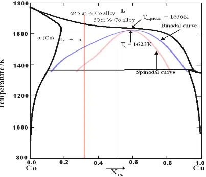
The phase diagram for the Co-Cu system, with calculated metastable binodal and spinodal lines
is in shown in Figure 3. The outer curve is the binodal curve while the inner one is the spinodal
curve. Tc and Tliquidus are the temperatures of the critical point and that of the liquidus at the
critical composition respectively. The two vertical lines show the composition of the Cu-50 at.
[image:11.595.77.480.228.575.2]% Co and the Cu-68.5 at. % Co alloys that are the focus of this study.
Figure 3: Metastable phase diagram of the Co-Cu system with calculated miscibility gap. In the binodal, the alloy is metastable and phase separation would occur by nucleation while in the spinodal region, the alloy is unstable and separation occurs via spontaneous fluctuations.
It may be seen from Figure 3 that the calculated critical point occurs at a composition of
Cu-41.3 at. % Co, wherein the critical temperature is 1623 K. The liquidus temperature at this
composition is 1636 K, giving a minimum undercooling for liquid phase separation (LPS) of
just 13 K. In contrast, for the Cu-50 at. % Co alloy the liquidus temperature is 1639 K with a
11
For the Cu-68.5 at. % Co composition the equivalent Figures are 1662 K for the liquidus, with
undercooling of 143 K and 256 K being required for binodal and spinodal decomposition
respectively.
3.2 Cooling rate
A plot of the estimated cooling rate as a function of droplet diameter for the Cu-50 at. % Co
alloy is shown in Figure 4, with the cooling rates varying from 8.39 x 10² K s-1 to 8.02 x 10⁴ K s -1 as the particle diameter decreases from 850 m to 38 m. The cooling rate for the Cu-68.5
at. % Co alloy is sufficiently similar to be indistinguishable on the scale of the figure, with a
variation between 8.61 x 10² K s-1 and 8.42 x 10⁴ K s-1 for 850 m and 38 m diameter particles respectively. The estimated cooling rates may be approximated by power law relationships of
the form (1.815 x 10⁷) (d/µm)-1.476 and (1.687 x 10⁷) (d/µm)-1.469 for the Cu-50 at. % Co and Cu-68.5 at. % Co alloys respectively. Thermophysical properties of the gas and melt, as used
[image:12.595.72.447.381.687.2]in the calculation, are listed in Table 1.
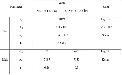
12 Parameter
Value
Units 50 at. % Co alloy 68.5 at. % Co alloy
Gas
g 1039
2.4 x 10⁻²
1.76 x 10⁻⁵
0.7619
J kg-1 K-1
K W m-1 K-1
g N s m-2
Pr
Melt
m 590 627 J kg-1 K-1
m 7885 7835 Kg m-3
[image:13.595.71.483.82.336.2]0.26 0.3
Table I: Thermophysical properties of nitrogen gas and Co – Cu melt.
3.3 Solidified Microstructures
In contrast to previous studies on drop-tube processed powders of metastable monotectic
alloys, diverse microstructures, which appear to be at various stages along the solidification
pathway, were observed in this study. Hence, the classification convention outlined below has
been adopted to avoid ambiguity, with examples of the various microstructural types being
shown in Figures 5 a-h.
1 NLPS: Non Liquid Phase Separated structures
i. NLPS_D: Dendrites (Figure 5a, mostly with visible secondary arms)
ii. NLPS_F: Fragmented dendrites (Figure 5b, with no visible secondary arms)
2 LPS: Liquid Phase Separated structures
i. SCS: Stable Core-shell structures (Figure 5c, comprising structures which
have perfect (or near perfect) spherical cores with concentric shell. Further
LPS by spinodal decomposition may be evident in the core only or in the
13
ii. ECS: Evolving Core-shell structures. This category consists of all
coalescing structures with distinct regions in them. These are mainly of two
types:
a) ECS_L: Loops (Figure 5d)
b) ECS_G: Globules (Figure 5e, also includes non-perfectly
formed SCS (Figure 5f))
iii. DPS: Distributed Phase Separated structures (Figure 5g)
iv. MS: Mixed Structures (Figure 5h)
In Figure 5, backscatter imaging gives rise to Z–contrast, in which the lighter of the two phases
is the Cu-rich phase by virtue of its higher atomic number. This was confirmed by EDX
measurement and colour contrast in optical microscopy, in which the Cu-rich phase displays
the characteristic tan colour of copper.
The classification scheme proposed holds true for both the 50 at. % Co and 68.5 at. % Co
compositions, there being no features which are unique to just one composition. Due to the
proximity of the binodal and spinodal curves in the Cu-50 at. % Co alloy, many structures in
this alloy are likely to have been formed by spinodal decomposition, either with or without
preceding binodal phase separation. Conversely, in the Cu - 68.5 at. % Co alloy, the high
undercooling required to access the spinode means that many structures are likely to have been
formed by binodal decomposition only.
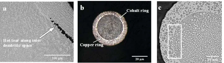
The dendritic droplets (Classification: NLPS - Figures 5a and b) were observed to have cobalt
rich dendrites within a copper rich matrix. The majority of the fully dendritic (Classification:
NLPS_D, Figure 5a) droplets were observed to have hot tears (Figure 6a), the presence of
which are likely due to shear stresses on the dendritic network occurring as a result of resistance
to flow of liquid metal through the evolving inter-dendritic network. Typically, hot tears occur
at high solid fraction towards the end of solidification. As such these would be expected to be
more likely in high cobalt alloys in which the volume fraction of Co-rich dendrites is higher.
However, the contrary was observed, with hot tears predominantly being observed in the 50 at.
% Co alloy. The reason for this is not clear. Hot tears were not observed in the droplets with
14
a
d
c
e
f
g
B
A
[image:15.595.71.446.69.664.2]h
b
Figure 5: SEM back scattered images showing representative microstructures in drop-tube processed Cu – 50 at. % Co alloy. In all images the dark (L1) phase is Co – rich and also the higher melting point
phase while the lighter (L2) phase is Cu – rich and the lower melting point phase. (a) and (b) show
NLPS structures: dendritic, fragmented dendrites respectively. (c) is a typical SCS structure while (d)
15
Figure 5c is an example of a two-layer core-shell morphology, characterised by a darker L1
phase (Co-rich) as the core at the centre of the droplet surrounded by a lighter coloured
Cu-rich shell. In the example micrograph given in Figure 5c the core contains many small dispersed
Cu-rich spherical particles, which is typical of the core-shell droplets produced during this
study. Conversely, the shell contains a mixture of Co-rich spherical particles and dendrites,
although other core-shell droplets are observed to contain only one or other of these type of
inclusions within the shell. Careful examination of Figure 5c reveals two rings around the core.
An example in which this is shown more prominently is given in Figure 6b, which clearly
shows an outer copper ring and an inner cobalt ring separating the main core and shell
structures. All of the SCS droplets analysed display these features, while many of the ECS
droplets display only a single ring separating the core from the shell. It is thought these rings
are segregation boundaries on the copper and cobalt rich sides of the core-shell interface
respectively. This can be seen more clearly in Figure 6c, where it is evident that the Cu-rich
ring is visible because it does not contain any Co-rich inclusions, presumably because any such
inclusions that form are able to easily migrate into the Co-rich core.
Figures 5d – f are the ECS type microstructures. In Figure 5d, a somewhat bi-continuous
structure is observed in which clear coalescence of the liquid phase separated Cu- and Co-rich
regions has occurred but in which complete migration of the Co-rich region to the centre of the
droplet has not yet occurred. The bulk Co-rich regions contain extensive Cu-rich inclusions,
both in the form of spherical particles and dendritic fragments. In contrast the bulk Cu-rich
regions contain fewer Co-rich inclusions, with those that are present being close to the
boundary with the bulk Co-rich region, suggesting that migration was in progress when
freezing occurred. In addition, there is clear evidence for the partial formation of a bulk,
Cu-rich shell. Figure 5e shows another ECS type droplet, probably one in which coalescence has
progressed further as there are now two well developed, bulk Co-rich regions. As with many
other droplets, the bulk Cu-rich region displays an extended network of Co dendrites while the
bulk Co-rich region contains numerous spherical Cu-rich inclusions. Careful examination of
these Cu-rich inclusions reveals filament like tails which suggest that the region is in motion.
The ECS structures are thought to be a continuous spectrum terminating at the SCS. Figure 5f
shows the final stage in the evolution towards the SCS structure, with a non-spherical
core-shell morphology. Although it might appear there is little difference between Figures 5(c) and
5(f), but based on the guideline adopted in knowing where to terminate the ECS classification
16
other classification out of this and which does not fit into the other classification is classified
ECS. Hence the difference between Figures 5(c) and 5(f).
Figures 5g is a distributed phase separated structure. This category is made up of all
non-coalesced, non-dendritic, uniformly distributed structures. The inclusions are mostly spherical
in shape and are presumably indicative of freezing occurring very soon after liquid phase
separation. Figure 5h shows a mixed structure, in which droplets display both NLPS and LPS
characteristics.
A very small number of droplets also appeared to have three layer, core-shell-corona or
matryoshka type structures. However, given the low numbers of such structures occurring we
consider that this could also arise due to section artefacts. In particular, a spherical droplet with
a structure as shown in Figure 7a, when sectioned along the line ‘X –X’, would erroneously
produce a core-shell-corona type structure, as shown in Figure 7b.
Figure 6: (a) Hot tears along the copper rich inter dendritic space of a NLPS droplet from the 850+ m size range of the Cu – 50 at. % Co alloy, (b) optical micrograph showing segregation rings in a SCS structure from the 53 – 38 m size range of the Cu – 68.5 at. % Co alloy and (c) magnified view of an SCS structure in which rectangular highlight show spherical particles at very close proximity to the copper and cobalt rings (droplet is from the Cu – 50 at. % Co alloy). Figures (a) and (c) are SEM backscatter images. (Dark (L1) phase is Co – rich while the lighter (L2) phase is Cu – rich). The minority phase in
all the figures is the lighter L2 phase while in (b) and (c) the darker majority and higher melting point
[image:17.595.78.440.345.448.2]17
a
b
[image:18.595.73.423.72.220.2]X
X
Figure 7: SEM backscatter images illustrating sectioning effect (along the line X-X in (a)) could be identified as a core-shell-corona structure (b). Droplet is from the 300 – 212 m size range of the Cu – 50 at. % Co alloy. High melting point dark (L1) phase is Co – rich while the lower melting point lighter
(L2) phase is Cu – rich.
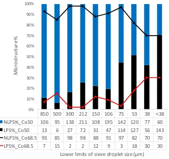
3.4 Microstructure variation
Figure 8 shows the frequency with which LPS and NLPS structures occur in the two alloys as
a function of sieve size. Droplets in the larger sieve size fraction of both alloys (d > 106 m)
consist mainly of the NLPS structures. However, it is also clear that across all size fractions
LPS structures are more common in the Cu-50 at. % Co alloy than in the 68.5 at. % Co alloy.
Both observations are to be expected as higher undercooling are required in the 68.5 at.% Co
alloy to access the binodal and spinodal transition than would be the case for the 50 at.% Co
18
850 500 300 212 150 106 75 53 38 <38 NLPS%_Co50 106 95 138 211 108 195 142 120 77 60 LPS%_Co50 13 6 27 72 31 47 114 127 56 143 NLPS%_Co68.5 93 85 98 98 88 91 97 82 70 70 LPS%_Co68.5 7 15 2 2 12 9 3 18 30 30
0% 10% 20% 30% 40% 50% 60% 70% 80% 90% 100% M ic ro st ru ct u re %
[image:19.595.100.432.76.388.2]Lower limits of sieve droplet size (µm)
Figure 8: Distribution of microstructural types as a function of droplet diameter in drop-tube processed Co-Cu alloys. More LPS structures were observed in the Cu-50 at. % Co alloy.
A further breakdown of the LPS structures for both alloys is shown in Figures 9a and b for the
50 at. % Co and 68.5 at. % Co alloys respectively. With reference to Figure 9a it can be seen
that for cooling rates in the range 103 K s-1 to 104 K s-1 (corresponding to droplets in the sieve
fractions from 300 m down to < 38 m) the whole range of LPS microstructures were
observed. The most striking feature of Figure 9a is the steady increase in the percentage of SCS
type microstructure as the cooling rate increases, with a maximum occurring at 2.7 x 10⁴ K s-1 (75 m diameter), wherein 87% of the sampled structures were of the SCS type. Thereafter,
for higher cooling rates there is a very steep decline in the percentage of SCS type structures
observed. This trend, and the associated converse trend in non-spherical (ECS, DP and MS)
structures, will reflect the time available after liquid phase separation for coalescence to occur,
which will itself be the result of the interplay between cooling rate and undercooling. At low
cooling rates low undercooling will be achieved so relatively little time will be available after
liquid phase separation for coalescence. As the cooling rate increases so does the undercooling,
giving longer for coalescence to occur. However, at very high cooling rates, despite large
19
available for coalescence again decreases, leading to an increase in partly coalesced (ECS) or
[image:20.595.71.466.114.475.2]non-coalesced (DP & MS) structures.
Figure 9a: Variation of phase separated structures with cooling rate / droplet diameter in the Cu-50
at. % Co alloy.
Similar arguments can also be used to explain the trend seen in Figure 9b for the 68.5 at. % Co
alloy. For cooling rates below 5000 K s-1 (d > 212 m) the higher undercooling required to initiate liquid phase separation means that virtually no time is available for coalescence, with
DP and MS structure dominating. Conversely, above cooling rates of 5000 K s-1 (d < 212 m)
there is sufficient time after liquid phase separation for coalescence to occur, leading to an
increase in SCS and ECS structures. This results in a maximum occurrence of SCS structures
(85%) at cooling rate of 1.5 x 10⁴ K s-1 (106 m diameter). These results show a distinctly different trend for metastable monotectic alloys to that found by Wang et al. [6] for stable
20
monotonically with decreasing particle size. This difference is explainable in terms of the
[image:21.595.75.457.114.466.2]cooling rate, and hence undercooling, required to initiate metastable liquid phase separation.
21 4 Discussion
Depending upon the undercooling achieved, solidification may occur either with, or without,
phase separation. The latter is more probable for the 68.5 at.% Co alloy due to the higher
undercooling required to access the binode/spinode, and for larger droplets where low cooling
rates will prevent high undercooling being achieved. Both trends are clearly evident in Figure
8, with relatively low proportions of LPS structures being observed for droplets larger than 300
m diameter. For structures solidified above the binodal temperature the predominant
microstructure is that of -Co dendrites (which may or may not be fragmented) in a Cu-rich
matrix.
Upon accessing deeper undercooling the droplet temperature will drop below the binode,
wherein liquid phase separation may occur, but only with nucleation. Although little discussed
within the literature, binodal liquid phase separation may occur via either a single, or multiple,
nucleation events. Moreover, if multiple nucleation sites are present these may be activated at
different times and therefore at different temperatures, resulting in phase separated liquids with
potentially different compositions. Such behaviour would be more likely for more
compositions away from the critical composition due to the larger difference between the
binodal and spinodal temperatures. One such droplet, which may potentially have experienced
such multiple nucleation events, is shown in Figure 10. The droplet, from the < 38 m sieve
fraction of the 68.5 at. % Co alloy, shows at least 16 isolated, near spherical, Co-rich regions
in a Cu-rich matrix. While it is impossible to completely rule out the occurrence of such a
structure by coalescence, the appearance is sufficiently different from the appearance of the
evolving structures in Figure 11a that we consider this to be unlikely and that the structure was
formed via multiple nucleation.
With yet higher cooling rates, undercooling to below the spinodal decomposition temperature
becomes possible, which may occur either with, or without, binodal decomposition occurring
first, depending upon the occurrence or otherwise of nucleation. In many of the samples studied
here there is clear evidence for two separate liquid phase separation events, which would
suggest binodal, followed by spinodal, decomposition. The microstructure in Figure 6c is an
example clearly showing two such separate events. We postulate that there was a primary phase
separation event (binodal) which resulted in the formation of the distinct Co- and Cu-rich
regions forming the core and shell. The second liquid phase separation is spinodal
22
very fine scale, of the Cu-rich particles contained within the Co-rich core in Figure 6c. More
detail is shown in Figure 11a and the associated insert, which shows an ECS structure. Bulk
separation of the droplet into Cu- and Co-rich regions has occurred but within the Co-rich
region an extremely fine distribution of Cu-rich droplets and filaments exists. The case for this
structure being formed by two separate LPS events is, we believe compelling, due to the
difference in scale between the bulk Cu-rich regions (> 20 m in length) and the fine dispersion
of Cu particles (50-1000 nm) within the Co-rich regions.
The occurrence of two separate LPS events also explains why the bulk Co-rich phase can
contain a fine dispersion of Cu-rich particles while the bulk Cu-rich phase may (Figure 6c) or
may not (Figure 11a) contain a similar fine dispersion of Co-rich particles. With reference to
the metastable phase diagram (Figure 3) we note that following binodal decomposition the
liquid will separate into compositions defined by the two points on the binodal curve that
correspond to the temperature at LPS was nucleated. The binodal and spinodal curves are
asymmetric, being stepper on the Cu-rich side than on the Co-rich side. The consequence of
this is that, following binodal decomposition, a higher undercooling is required to initiate
spinodal decomposition of the Cu-rich liquid than is required for the Co-rich liquid. Freezing
is therefore possible subsequent to secondary (spinodal) decomposition of the Co-rich liquid
but prior to secondary decomposition of the Cu-rich liquid. Similar arguments can be invoked
to explain why SCS structure with a secondary LPS core can show dendritic, non-dendritic or
mixed shells. In randomly selected SCS structures across the whole sieve fraction size range in
the Cu - 50 at. % Co alloy, the ratio of dendritic to LPS to mixed shells was found to be 3:6:1.
These findings, while being consistent with the asymmetric miscibility gap calculated above
[image:23.595.71.255.566.713.2]are not consistent with the near symmetric miscibility gap determined by Cao et al. [26].
23
Figures 11 a-c, show ECS type droplets which appear to be at different stages along the
solidification pathway. The structures shown in Figure 11 a & b are both at the early stages of
formation, wherein Marangoni convection will be driving the higher melting point phase
towards the centre of the droplet. Indeed, in Figure 11b the outline of a proto-shell of Cu-rich
liquid is clearly visible. In the droplet shown in Figure 11c (from the Cu-68.5 at.% Co alloy),
the process of coalescence and migration is much further advanced, although not complete as
witnessed by the highly irregular shape of the core, which is also offset from the centre of the
droplet. These structures serve to illustrate the complex interplay between LPS (of which there
may be one or two separate events) and freezing, giving rise to a wide variety of as-solidified
structures.
Shi et al. [1] in their phase field simulations stated that the bi-continuous structure formed by
spinodal decomposition would coalesce to form a range of structures that were dependent upon
the volume fraction of the two phases present. They found that the majority phase would always
segregate to the shell and the minority phase to the core. In the interesting case of the two
volume fractions being equal, they simulated a structure in which one phase segregated to one
hemisphere of the sample and the other phase to the other hemi-sphere (see their Figure 8). In
this experimental study we found no microstructural evidence to support the structures
[image:24.595.68.502.460.627.2]predicted by Shi et al.
Figure 11: SEM backscatter images showing ECS structures at different stages along the
24
Indeed, in contradiction to the work of Shi et al. and many earlier reports in the literature [14–
16], the experimental results in both the alloys studied show that the volume fraction of the
shell (L2) phase varied from 10 to 82%. The formation mechanism of the core shell structure
is not discussed in detail in this paper, as this has been dealt with extensively elsewhere (see
e.g. [6,14,15,22]) and the basic details of the process we do not consider to be controversial.
However, we deal specifically with two observations related to the formation of core-shell
structures. The first is that of structures intermediate between initial liquid phase separation
and full core-shell development. The second is the question of which phase forms the core and
which the shell. It is clear within the previous work on core-shell formation that there will be
a delay between initial liquid phase separation and full core-shell development, this being
dependent upon various factors including alloy composition and the cooling regime the droplet
is subject to. At the physical level this delay arises from the time needed for Marangoni
convection to transport material to the centre/surface of the droplet. Implied within this is the
fact that, given that solidification of the droplet could terminate this Marangoni driven
segregation process at any point, a spectrum of intermediate states comprising greater or lesser
degrees of evolution towards full core-shell structures should arise. This is explored in detail
within this work with Figures 8 and 9 providing statistical data on the prevalence of these
intermediate states. The reason why such a broad range of intermediate structures are observed
is due to the interplay between cooling rate, undercooling and nucleation in drop-tube samples.
The cooling rate, which will determine the time available for Marangoni convection, is a
deterministic function of droplet size. In contrast, the undercooling achieved by a given droplet,
which will determine the onset of liquid phase separation is stochastic. Smaller droplets will
have a higher probability of a high undercooling, but within each size fraction individual
droplets could experience a widely different undercooling. Finally, nucleation of solidification
can intervene at any point during liquid phase migration, leading to transient features being ‘frozen in’. In this respect we note the observation of Kaban et al. [35] that materials that are effective nuclei for initiating demixing are not necessarily be the best nuclei for solidification
and that therefore nucleation of liquid phase separation and nucleation of solidification are
decoupled.
The second point relates to which of the two phases forms the core, and specifically whether
this is always the higher melting point phase or the majority phase, both having been proposed
in the literature. In this work we find that the core is always the Co-rich phase, irrespective of
25
but in both cases the volume fraction of the Cu - rich phase will increase with undercooling.
This is due to the asymmetry of the binodal curve which causes a more rapid enrichment of the
Cu - rich liquid compared to the rate of enrichment of the Co – rich liquid. A simple Lever rule
calculation yields the volume fractions of the two phases as a function of undercooling, which
is shown in Figure 12, for the Cu-50 at. % Co. The implication of this is that growth of the L2
(shell) phase is at the expense of the core (L1) phase. Consequently, at high undercooling
droplets with a majority shell may be formed. Several droplets in which the shell were the
majority phase were observed in this study, one of which is shown in Figure 13, in which the
L2 phase has a volume fraction of 76%. Moreover, Cao et al. [36] studied the Co – 68.5 at. %
Cu alloy which is on the Cu – rich side of the miscibility gap. Their observed microstructure
clearly show that the dispersed particles and the core was the Co – rich (L1) phase. This further
confirms that whether the L1 phase is the minority phase or not, it always forms the core in the
Co – Cu system.
The SCS structures formed were however found consistent with other reports in the literature
in that the core was always the higher melting point phase irrespective of its volume fraction.
If this were not the case a reversal of the core and shell materials would be expected from one
alloy to the other and this was never observed. The morphology of the observed SCS structures
were consistent in both alloys implying that the impact of volume fraction on phase selection
in the metastable immiscible Co-Cu alloys was minimal.
This observation is consistent with the findings of Ohnuma et al. [16] that rather than the
volume fraction, the surface tension of the two liquids determine the phase forming the core.
In our experiment, the higher melting point phase (here the Co – rich phase) has the higher
surface tension which in turn drives inward migration. This is in line with the observation that
in Co-Cu alloys, surface segregation arises due to the phase with the lower surface tension
completely wetting the higher energy phase and adhering to the surface of the parent droplet in
26 0.4
0.1 0.2 0.3 0.5
0
Shell volume fraction
100 500
200 300 400
U
n
d
e
rc
o
o
lin
g
/
[image:27.595.78.420.70.351.2]K
Figure 12: Calculated variation of the shell (L2) phase volume fraction as a function of undercooling based on the binodal curve shown in Figure 3 and Lever.
Figure 13: SEM backscatter image showing core shell structure in which the lighter Cu - rich (L2)
[image:27.595.73.363.429.674.2]27 5. Summary & Conclusion
The occurrence of liquid phase separation has been investigated in 50 at. % Co and
Cu-68.5 at. % Co alloys, rapidly solidified via drop-tube processing. At low cooling rates (large
diameter droplets) both alloys tend to solidify prior to liquid phase separation, with significant
numbers of LPS structures only being observed once the cooling rate exceeds 15000 K s-1. In droplets experiencing liquid phase separation a range of morphologies were observed
including: stable core-shell structures, evolving core-shell structures and structures in which
the immiscible liquids were randomly distributed. The frequency with which these structures
occur has been characterised as a function of cooling rate with it being found that for both
alloys there is an optimum cooling rates for the formation of stable core-shell structures. This
trend is explainable in terms of the balance between undercooling and the time available for
coalescence, both of which are functions of cooling rate.
In many droplets two episodes of liquid phase separation were observed, with bulk LPS regions
displaying a very fine dispersion of the other phase. This type of segregation pattern appears
to result from binodal decomposition followed by spinodal decomposition upon further
undercooling. The microstructural evidence suggests that this occurs first in the core of the
core-shell particles, with many particles displaying secondary segregation in the Co-rich core
but not in the Cu-rich shell. This trend may be accounted for by the asymmetry in the binodal
and spinodal curves, with higher undercooling being required to access the spinode for a
Cu-rich liquid following binodal decomposition than would be the case for a Co-Cu-rich liquid.
Irrespective of the alloy composition the core was always observed to be the Co-rich liquid and
the shell the Cu-rich liquid. This is in contradiction to some reports that suggest that the
minority phase always forms the core. We find no evidence for this, finding instead that the
core always comprises the higher melting point phase. This is consistent with the low melting
point phase having the lower surface tension and hence being able to wet the surface of the
28 Acknowledgement
Oluwatoyin Jegede is a commonwealth scholar, sponsored by the UK government.
Conflict of interest: The authors declare they have no conflict of interest related to this work.
References
[1] R.P. Shi, C.P. Wang, D. Wheeler, X.J. Liu, Y. Wang, Formation mechanisms of self-organized core/shell and core/shell/corona microstructures in liquid droplets of immiscible alloys, Acta Mater. 61 (2013) 1229–1243.
[2] A. V. Nomoev, S.P. Bardakhanov, M. Schreiber, D.G. Bazarova, N.A. Romanov, B.B. Baldanov, B.R. Radnaev, V. V. Syzrantsev, Structure and mechanism of the formation of core-shell nanoparticles obtained through a one-step gas-phase synthesis by electron beam evaporation, Beilstein J. Nanotechnol. 6 (2015) 874–880.
[3] R. Hayes, A. Ahmed, T. Edge, H. Zhang, Core-shell particles: Preparation, fundamentals and applications in high performance liquid chromatography, J. Chromatogr. A. 1357 (2014) 36–52.
[4] R. Dai, S.G. Zhang, Y.B. Li, X. Guo, J.G. Li, Phase separation and formation of core-type microstructure of Al-65.5 mass% Bi immiscible alloys, J. Alloys Compd. 509 (2011) 2289–2293.
[5] R. Shi, Y. Wang, C. Wang, X. Liu, Self-organization of core-shell and core-shell-corona structures in small liquid droplets, Appl. Phys. Lett. 98 (2011) 204106.
[6] N. Wang, L. Zhang, Y.L. Peng, W.J. Yao, Composition-dependence of core-shell microstructure formation in monotectic alloys under reduced gravity conditions, J. Alloys Compd. 663 (2016) 379–386.
[7] R. Dai, J.F. Zhang, S.G. Zhang, J.G. Li, Liquid immiscibility and core-shell
morphology formation in ternary Al-Bi-Sn alloys, Mater. Charact. 81 (2013) 49–55.
[8] B. Ma, J. Li, Z. Peng, G. Zhang, Structural morphologies of Cu-Sn-Bi immiscible alloys with varied compositions, J. Alloys Compd. 535 (2012) 95–101.
[9] Y. Yu, X. Liu, Z. Jiang, C. Wang, R. Kainuma, K. Ishida, Thermodynamics and liquid phase separation in the Cu–Co–Nb ternary alloys, J. Mater. Res. 25 (2010) 1706–1717.
[10] M. Kolbe, C.D. Cao, X.Y. Lu, P.K. Galenko, B. Wei, D.M. Herlach, Solidification behaviour of undercooled Co-Cu alloys showing a metastable miscibility gap, Mater. Sci. Eng. A. 375–377 (2004) 520–523.
[11] C.P. Wang, X.J. Liu, R.P. Shi, C. Shen, Y. Wang, I. Ohnuma, R. Kainuma, K. Ishida, Design and formation mechanism of self-organized core/shell structure composite powder in immiscible liquid system, Appl. Phys. Lett. 91 (2007) 1–4.
[12] W.Q. Lu, S.G. Zhang, J.G. Li, Macrosegregation driven by movement of minor phase in (Al0.345Bi0.655)90Sn10 immiscible alloy, Appl. Phys. A. 117 (2014) 787 - 792.
29
[14] N. Wang, L. Zhang, Y.P. Zheng, W.J. Yao, Shell phase selection and layer numbers of core-shell structure in monotectic alloys with stable miscibility gap, J. Alloys Compd. 538 (2012) 224–229.
[15] C.P. Wang, X.J. Liu, I. Ohnuma, R. Kainuma, K. Ishida, Formation of immiscible alloy powders with egg-type microstructure, Science (80) 297 (2002) 990–993.
[16] I. Ohnuma, T. Saegusa, Y. Takaku, C.P. Wang, X.J. Liu, R. Kainuma, K. Ishida, Microstructural Evolution of Alloy Powder for Electronic Materials with Liquid Miscibility Gap, J. Electron. Mater. 38 (2009) 2–9.
[17] R. Dai, S. Zhang, X. Guo, J. Li, Formation of core-type microstructure in Al–Bi monotectic alloys, Mater. Lett. 65 (2011) 322–325.
[18] Z. Sun, X. Song, Z. Hu, G. Liang, S. Yang, R.F. Cochrane, Effects of Ni addition on liquid phase separation of Cu–Co alloys, J. Alloys Compd. 319 (2001) 276–279.
[19] C. Xu, R. Du, X.J. Wang, S. Hanada, H. Yamagata, W.H. Wang, C.L. Ma, Effect of cooling rate on morphology of primary particles in Al-Sc-Zr master alloy, Trans. Nonferrous Met. Soc. China (English Ed. 24 (2014) 2420–2426.
[20] T. Qin, H. Wang, B. Wei, Simulated evolution process of core-shell microstructures, Sci. China Ser. G Physics, Mech. Astron. 50 (2007) 546–552.
[21] J.P. Heath, J.S. Dean, J.H. Harding, D.C. Sinclair, Simulation of impedance spectra for core-shell grain structures using finite element modeling, J. Am. Ceram. Soc. 1931 (2015) 1925–1931.
[22] K. Wang, C. Cui, Q. Wang, S. Liu, C. Gu, The microstructure and formation mechanism of core–shell-like TiAl3/Ti2Al20Ce in melt-spun Al–Ti–B–Re grain refiner, Mater. Lett. 85 (2012) 153–156.
[23] B.C. Luo, H.P. Wang, B.B. Wei, Phase field simulation of monotectic transformation for liquid Ni-Cu-Pb alloys, Chinese Sci. Bull. 54 (2009) 183–188.
[24] M.B. Robinson, D. Li, T.J. Rathz, G. Williams, Undercooling, liquid separation and solidification of Cu-Co alloys, J. Mater. Sci. 34 (1999) 3747–3753.
[25] Y. Nakagawa, Liquid immiscibility in copper-iron and copper-cobalt systems in the supercooled state, Acta Metall. 6 (1958) 704–711.
[26] C.D. Cao, Z. Sun, X.J. Bai, L.B. Duan, J.B. Zheng, F. Wang, Metastable phase diagrams of Cu-based alloy systems with a miscibility gap in undercooled state, J. Mater. Sci. 46 (2011) 6203–6212.
[27] A. Munitz, R. Abbaschian, Two-melt separation in supercooled Cu-Co alloys solidifying in a drop-tube, J. Mater. Sci. 26 (1991) 6458–6466.
[28] S.P. Elder, A. Munitz, G.J. Abbaschian, Metastable Liquid Immiscibility in Fe-Cu and Co-Cu Alloys, Mater. Sci. Forum. 50 (1989) 137–150.
[29] A. Munitz, R. Abbaschian, Microstructure of Cu-Co Alloys Solidified at Various Supercoolings, Metall. Mater. Trans. A. 27 (1996) 4049–4059.
[30] A. Munitz, R. Abbaschian, Liquid separation in Cu – Co and Cu – Co – Fe alloys solidified at high cooling rates, Mater. Sci. 33 (1998) 3639–3649.
30
[32] T. Nishizawa, K. Ishida, The Co−Cu (Cobalt-Copper) system, Bull. Alloy Phase Diagrams. 5 (1984) 161–165.
[33] X. Liu, X. Lu, B. Wei, Rapid monotectic solidification under free fall condition, Sci. China Ser. E Technol. Sci. 47 (2004) 409–420.
[34] O. Oloyede, T.D. Bigg, R.F. Cochrane, A.M. Mullis, Microstructure evolution and mechanical properties of drop-tube processed, rapidly solidified grey cast iron, Mater. Sci. Eng. A. 654 (2016) 143–150.
[35] I. Kaban, M. Köhler, L. Ratke, W. Hoyer, N. Mattern, J. Eckert, A.L. Greer, Interfacial tension, wetting and nucleation in Al-Bi and Al-Pb monotectic alloys, Acta Mater. 59 (2011) 6880–6889.
[36] C. Cao, T. Letzig, G. Görler, D. Herlach, Liquid phase separation in undercooled Co– Cu alloys processed by electromagnetic levitation and differential thermal analysis, J. Alloys Compd. 325 (2001) 113–117.
[37] W.Q. Lu, S.G. Zhang, J.G. Li, Macrosegregation driven by movement of minor phase in (Al0.345Bi0.655)90Sn10immiscible alloy, Appl. Phys. A Mater. Sci. Process. 117 (2014) 787–792.
![Figure 1: Different core-shell structure configurations likely in a binary monotectic system, (a) (e) core-shell particle with inclusions in the core and (f) core-shell particle with embedded multiple spherical particles in both the core and shell [6].spherical core-shell [4], (b) core-shell particle with multiple cores, (c) multiple shell /matryoshka / onion like core-shell particle [5], (d) core-shell particle with embedded multiple spherical particles in the shell,](https://thumb-us.123doks.com/thumbv2/123dok_us/1982420.159791/3.595.84.418.301.508/different-structure-configurations-monotectic-inclusions-spherical-spherical-matryoshka.webp)