UNIVERSITI TEKNIKAL MALAYSIA MELAKA
[image:1.612.243.413.131.232.2]OPTIMISATION AND ANALYSATION OF LINEAR POSITIONING
TABLE FOR DRILLING MACHINE
This report submitted in accordance with the requirement of the Universiti Teknikal Malaysia Melaka (UTeM) for the Bachelor of Manufacturing Engineering Technology
(Process and Technology) with Honours
by
SITI HAIDAR ATIAH BINTI MOHD AZMI
B071410368
950211-03-5596
i
DECLARATION
I hereby, declared this report entitled Optimisation and Analysation of Linear Positioning Table for Drilling Machine is the results of my own research except as
cited in references.
Signature : ………
ii
APPROVAL
This report is submitted to the Faculty of Engineering Technology of UTeM as a partial fulfillment of the requirements for the degree of Bachelor of Manufacturing Engineering Technology (Process and Technology) with Honours. The member of the supervisory is as follow:
iii
ABSTRAK
iv
ABSTRACT
v
DEDICATION
I dedicate this thesis to my great family especially my father, Mohd Azmi Bin Ismail, my mother, Hasiah Binti Jaafar and my siblings, Siti Hajar, Mohamad Zahid, Ahmad Taufiq Al Haq and Siti Fatihah Atihkah who never stop giving off themselves in countless ways. For their endless love, support and encouragement to keep me move forward.
vi
ACKNOWLEDGEMENT
In the name of Allah, the Most Merciful, the Most Compassionate all praise be to Allah, the Lord of the worlds and praise be upon Muhammad His servant and messenger, I would like to take this time to thank my supervisor or research advisor Dr. Norfariza Binti Ab Wahab and my co-supervisor Mr Abd Khahar Bin Nordin for the opportunity to undertake this research project. They have provided me with endless amounts of support and guidance throughout the entire project. I really appreciate all the ideas, knowledges and valuable advices that they had given to me.
Special thanks to all the assistant engineers, Mr Norhisham Bin Abdul Malik, Mr Basri Bin Bidin, Mr Mohd Azimin Bin Ibrahim, Mr Mohd Syafiq Bin Ismail, Mr Zulkifli Bin Jantan, the late of Mr Khairul Efendy Bin Mansor, Mr Fakhrulnaim Bin Ibrahim, Mr Azizul Ikhwan Bin Mohd and Mr Nor Fauzi Bin Tamin that willing to share all the ideas, opinions, knowledges and give advises that is needed to finish optimized this project successfully. I really appreciate their time and effort in guiding me when using all the machines and equipment in the lab.
vii
TABLE OF CONTENT
Declaration i
Approval ii
Abstrak iii
Abstract iv
Dedication v
Acknowledgement vi
Table of Content vii
List of Tables x
List of Figures xi
List of Symbols and Abbreviations xiv
Chapter 1: Introduction
1.1 Overview 1
1.2 Background of Study 1
1.2.1 Clamping Method 1
1.2.2 Characteristics of Drilling Machine 2
1.2.2.1Spindle 3
1.2.2.2Sleeve 4
1.2.2.3Column 4
1.2.2.4Head 4
1.2.2.5Work Table 5
viii
1.2.3 Types of Drilling Machine 5
1.3 Problem Statement 6
1.4 Objectives 7
1.5 Project Scopes 7
CHAPTER 2: LITERATURE REVIEW
2.1 Overview 8
2.2 Introduction of Machining Process 8
2.2.1 Conventional Machining Process 10
2.2.2 Advanced Machining Process 12
2.3 Machining Operations 19
2.4 Drill Press 20
2.5 Effect of Clamping 22
2.5.1 Machining Forces 24
2.5.2 Distortion 26
CHAPTER 3: METHODOLOGY
3.1 Overview 27
3.2 Introduction 27
3.3 Part Identification 30
3.4 Optimization of Design 32
3.5 Optimization of Result 34
3.6 Analyze the Product 35
ix CHAPTER 4: RESULT AND DISCUSSION
4.1 Introduction 36
4.2 Presentation of Findings 36
4.2.1 Part Used 37
4.2.2 Finished Optimize of Product 38
4.3 Optimization Process 39
4.3.1 L-Shape Plate 39
4.3.2 Stopper Bar 43
4.3.3 Base Rail 45
4.3.4 Hand Wheel 47
4.3.5 Supporter Plate 48
4.3.6 Top Beam 51
4.3.7 Wood Table 53
4.3.8 Scale Reading 54
4.3.9 Part Assembly 55
4.4 Optical Comparator 57
4.5 Experiment Setup 59
4.6 Discussion 68
CHAPTER 5: CONCLUSION AND RECOMMENDATION
5.1 Introduction 71
5.2 Summary Findings 71
5.3 Project Limitation 72
5.4 Conclusion 72
5.5 Recommendations 73
References 75
x
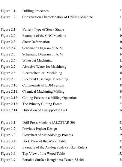
[image:11.612.118.507.131.537.2]LIST OF TABLES
Table 3.1: Parameters Setup of Previous Project 34
Table 3.2: Parameters Setup for Optimize Project 34
Table 4.1: Part Used 37
Table 4.2: Parameter Setup 61
Table 4.3: Aluminum (t=2mm), Drill Bit = 3.5mm – use 62 Table 4.4: Aluminum (t=2mm), Drill Bit = 3.5mm – not use 62 Table 4.5: Aluminum (t=2mm), Drill Bit = 5mm – use 62 Table 4.6: Aluminum (t=2mm), Drill Bit = 5mm – not use 62 Table 4.7: Mild Steel (t=1.6mm), Drill Bit = 3.5mm – use 63 Table 4.8: Mild Steel (t=1.6mm), Drill Bit = 3.5mm – not use 63 Table 4.9: Mild Steel (t=1.6mm), Drill Bit = 5mm – use 63 Table 4.10: Mild Steel (t=1.6mm), Drill Bit = 5mm – not use 63 Table 4.11: Acrylic (t=4mm), Drill Bit = 5mm – use 64 Table 4.12: Acrylic (t=4mm), Drill Bit = 5mm – not use 64
Table 4.13: For the sample of 3.5 mm 64
Table 4.14: For the sample of 5 mm 64
Table 4.15: Previous Result, Aluminum of T=1mm, Drill Bit 3.5mm 66
xi
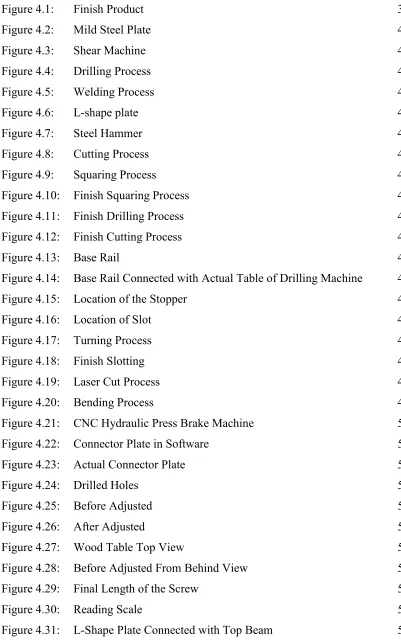
LIST OF FIGURES
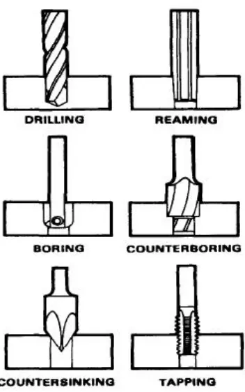
Figure 1.1: Drilling Processes 2
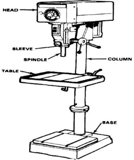
Figure 1.2: Construction Characteristics of Drilling Machine 3
Figure 2.1: Variety Type of Stock Shape 9
Figure 2.2: Example of the CNC Machine 10
Figure 2.3: Shear Deformation 10
Figure 2.4: Schematic Diagram of AJM 14
Figure 2.5: Schematic Diagram of AJM 14
Figure 2.6: Water Jet Machining 15
Figure 2.7: Abrasive Water Jet Machining 16
Figure 2.8: Electrochemical Machining 16
Figure 2.9: Electrical Discharge Machining 17
Figure 2.10: Components of EDM system 18
Figure 2.11: Chemical Machining/Milling 19
Figure 2.12: Cutting Forces in a Milling Operation 24
Figure 2.13: The Primary Cutting Forces 25
Figure 2.14: Distortion of Unsupported Part 26
Figure 3.1: Drill Press Machine (ALZSTAR 30) 28
Figure 3.2: Previous Project Design 28
Figure 3.3: Flowchart of Methodology Process 29
Figure 3.4: Back View of the Wood Table 32
Figure 3.5: Example of the Analog Scale (Sticker Ruler) 33
[image:12.612.111.518.111.668.2]Figure 3.6: Top View of the Wood Table 33
xii
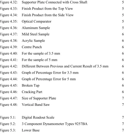
Figure 4.1: Finish Product 39
Figure 4.2: Mild Steel Plate 40
Figure 4.3: Shear Machine 40
Figure 4.4: Drilling Process 41
Figure 4.5: Welding Process 41
Figure 4.6: L-shape plate 42
Figure 4.7: Steel Hammer 42
Figure 4.8: Cutting Process 43
Figure 4.9: Squaring Process 43
Figure 4.10: Finish Squaring Process 44
Figure 4.11: Finish Drilling Process 44
Figure 4.12: Finish Cutting Process 45
Figure 4.13: Base Rail 45
Figure 4.14: Base Rail Connected with Actual Table of Drilling Machine 46
Figure 4.15: Location of the Stopper 46
Figure 4.16: Location of Slot 47
Figure 4.17: Turning Process 47
Figure 4.18: Finish Slotting 48
Figure 4.19: Laser Cut Process 49
Figure 4.20: Bending Process 49
Figure 4.21: CNC Hydraulic Press Brake Machine 50
Figure 4.22: Connector Plate in Software 50
Figure 4.23: Actual Connector Plate 51
Figure 4.24: Drilled Holes 51
Figure 4.25: Before Adjusted 52
Figure 4.26: After Adjusted 52
Figure 4.27: Wood Table Top View 53
Figure 4.28: Before Adjusted From Behind View 53
Figure 4.29: Final Length of the Screw 54
[image:13.612.112.513.69.709.2]Figure 4.30: Reading Scale 54
xiii
Figure 4.32: Supporter Plate Connected with Cross Shaft 55
Figure 4.33: Finish Product from the Top View 56
Figure 4.34: Finish Product from the Side View 56
Figure 4.35: Optical Comparator 58
Figure 4.36: Aluminum Sample 59
Figure 4.37: Mild Steel Sample 60
Figure 4.38: Acrylic Sample 60
Figure 4.39: Centre Punch 61
Figure 4.40: For the sample of 3.5 mm 65
Figure 4.41: For the sample of 5 mm 65
Figure 4.42: Different Between Previous and Current Result of 3.5 mm 66 Figure 4.43: Graph of Percentage Error for 3.5 mm 67 Figure 4.44: Graph of Percentage Error for 5 mm 68
Figure 4.45: Broken Tap 69
Figure 4.46: Cracking Part 69
Figure 4.47: Size of Supporter Plate 70
Figure 4.48: Vertical Band Saw 70
Figure 5.1: Digital Readout Scale 73
Figure 5.2: 3 Component Dynamometer Types 9257BA 74
xiv
LIST OF SYMBOLS AND ABBREVIATIONS
CNC - Computer Numerical Control Mm - Milimeter
1
CHAPTER 1
INTRODUCTION
1.1 Overview
This chapter is discussed about the background of the study about the drilling process and a few clamping method. Other than that, the characteristic of drilling machine is also being explained and the type of drilling machine that selected is press drill machine. Besides, there are also a list of types of drilling machine and the problems that can be identified in this project. After the problem is come up, the objectives for this study can also be recognized to find the solution. The last part in this chapter is talked about the project scope that will be cover on this project.
1.2 Background of the Study
2
Figure 1.1: Drilling Processes
[
https://smithy.com/sites/default/files/media/jpg/machining%20handbook/Chapter_6/6-2.jpg ]
1.2.1 Clamping Method
3
i. The clamp should allow rapid loading and unloading of parts and be fast-acting.
ii. The clamp should not deform the part of damage it.
iii. The clamp must have enough strength to restrict its movement and hold the parts.
1.2.2 Characteristics of Drilling Machine
[image:18.612.216.443.311.583.2]All drilling machines have the following construction characteristics: a spindle, sleeve or quill, column, head, worktable, and base.
Figure 1.2: Construction Characteristics of Drilling Machine
[ https://smithy.com/machining-handbook/chapter-6/page/1]
4 1.2.2.1 Spindle
The spindle holds the drill or cutting tools and revolves in a fixed position in a sleeve. In most drilling machines, the spindle is vertical and the work is supported on a horizontal table.
1.2.2.2 Sleeve
The sleeve or quill assembly does not revolve but may slide in its bearing in a direction parallel to its axis. When the sleeve carrying the spindle with a cutting tool is lowered, the cutting tool is fed into the work: and when it is moved upward, the cutting tool is withdrawn from the work. Feed pressure applied to the sleeve by hand or power causes the revolving drill to cut its way into the work a few thousandths of an inch per revolution.
1.2.2.3 Column
The column of most drill presses is circular and built rugged and solid. The column supports the head and the sleeve or quill assembly.
1.2.2.4 Head
5 1.2.2.5 Work Table
The worktable is supported on an arm mounted to the column. The worktable can be adjusted vertically to accommodate different heights of work or it may be swung completely out of the way. It may be tilted up to 90° in either direction, to allow for long pieces to be end or angled drilled.
1.2.2.6 Base
The base of the drilling machine supports the entire machine and when bolted to the floor, provides for vibration-free operation and best machining accuracy. The top of the base is similar to a worktable and maybe equipped with T-slots for mounting work too large for the table.
1.2.3 Types of Drilling Machine
Drilling machine has variety of types. Some of them are as follows: 1. Portable drilling machine
2. Bench type drilling machine 3. Sensitive drilling machine
Bench mounting
Floor mounting 4. Upright drilling machine
Round column section
6 5. Radial drilling machine or Radial arm press
Plain
Semi-universal
Universal
6. Gang drilling machine
7. Multiple spindle drilling machine 8. Automatic drilling machine 9. Deep hole drilling machine
Vertical
Horizontal
1.3 Problem Statement
1. The linear positioning table for the drilling machine is manually moves for x-axis.
2. The scale reading does not require on the linear positioning table for drilling machine.
7 1.4 Objectives
The objective of this project is to optimize and analyze the linear positioning table for drilling machine. The specific research tasks to fulfill the objectives of this thesis are summarized as follows:
1. To modify the linear positioning table for drilling machine.
2. To optimize the design and experiment result of linear positioning table for drilling machine.
3. To analyze the experiment result of linear positioning table for drilling machine.
1.5 Project Scopes
This project will only cover on:
8
CHAPTER 2
LITERATURE REVIEW
2.1 Overview
In chapter two, literature review contains the current knowledge included essential findings as well as the theoretical contribution to a specific subject or topic. There will be a introduction of machining process, machining operation, about the drill press and the effect of clamping.
2.2 Introduction of Machining Process
9
Flat sheet
Rectangular bar
Round tube
[image:24.612.113.539.68.390.2]I-beam
Figure 2.1: Variety Type of Stock Shape
[http://www.custompartnet.com/wu/machining]