City, University of London Institutional Repository
Citation
:
Tanghetti, G., Goodey, R.J. ORCID: 0000-0002-9166-8393, Divall, S.,McNamara, A. M. and Mckinley, B. (2019). Design and development of a large shear box for testing working platform material. Paper presented at the ECSMGE - 2019. XVII European Conference on Soil Mechanics and Geotechnical Engineering, 1 - 6 September 2019, Reykjavik, Iceland.
This is the accepted version of the paper.
This version of the publication may differ from the final published
version.
Permanent repository link:
http://openaccess.city.ac.uk/21985/Link to published version
:
Copyright and reuse:
City Research Online aims to make research
outputs of City, University of London available to a wider audience.
Copyright and Moral Rights remain with the author(s) and/or copyright
holders. URLs from City Research Online may be freely distributed and
linked to.
City Research Online: http://openaccess.city.ac.uk/ [email protected]
Geotechnical Engineering foundation of the future
ISBN 978-0-7277-6067-8
© The authors and IGS: All rights reserved, 2019 doi:17ecsmge-2019-Y-XXXX
Design and development of a large shear box for
testing working platform material
Conception et développement d'une grande boîte de cisaillement pour
tester le matériel de la plateforme de travail
G. Tanghetti, R. J. Goodey, S. Divall, A. M. McNamara, B. McKinley
City, University of London, London, UK
ABSTRACT: On large construction projects where deep foundations are to be installed, a working platform is placed across the entire site. This is comprised of a layer of aggregate (often crushed construction waste) usually with a particle size ranging from 120 mm downwards. Deep foundations are installed using heavy and tall drilling rigs and the working platform is thus safety critical to reduce the risk of machinery sinking and/or toppling which would lead to accidents and often serious injury to workers. Currently available design guidance is felt to result in conservative designs and there are many benefits to be gained from a greater understanding of the behaviour of working platform material. The design of these platforms is primarily governed by the angle of friction of the platform material. The measurement of friction angle for geomaterials that have large particle sizes is problematic (due to reasons of scale) and is often addressed by scaling down the material's grading curve prior to testing in small to medium size direct shear apparatus. The work presented here details the design of and the rationale for a large scale direct shear apparatus suitable for testing geomaterials with particle size distributions of the type that would be utilised in working platforms.
RÉSUMÉ: Sur les grands projets de construction où des fondations profondes doivent être installées, une plate-forme de travail est installée sur l'ensemble du site. Celle-ci est composée d'une couche d'agrégat (souvent des déchets de construction broyés), généralement avec une taille de particule allant de 120 mm vers le bas. Les fondations profondes sont installées à l'aide d'appareils de forage lourds et hauts. La plate-forme de travail est donc essentielle pour la sécurité afin de réduire les risques de fauchage et / ou de renversement de la machine, susceptible de générer des accidents et souvent des blessures graves pour les travailleurs. On pense que les di-rectives de conception actuellement disponibles se traduisent par des conceptions conservatrices et une meilleure compréhension du comportement du matériau de la plate-forme de travail présente de nombreux avantages. La conception de ces plates-formes est principalement régie par l'angle de friction du matériau de la plate-forme. La mesure de l'angle de frottement pour les géomatériaux ayant de grosses tailles de particules est problématique (pour des raisons d'échelle) et est souvent abordée en réduisant la courbe de classement du matériau avant de le tester dans des appareils de cisaillement direct de taille petite à moyenne. Le travail présenté ici détaille la con-ception et la raison d'être d'un appareil de cisaillement direct à grande échelle adapté au test de géomatériaux présentant une distribution granulométrique du type qui serait utilisé sur les plates-formes de travail.
Design and development of a large shear box for testing working platform material
1
INTRODUCTION
A working platform represents a ground-sup-ported structure consisting of coarse granular ma-terial, used as a safe and sufficiently durable sur-face from which construction plant, such as piling rigs and cranes, can operate. Nowadays, the use of recycled material (mostly construction demo-lition waste like brick and concrete) has become common practice for the construction of working platforms thus reducing the costs related to ex-traction and transportation of granular material and the risk of incidents during quarrying opera-tions and lorry movements. Further benefits asso-ciated with the use of recycled material derive from the reduction in environmental damage due to the extraction of primary aggregates, transpor-tation of materials and landfilling.
Despite the main purpose of these structures being to provide reinforcement to the natural ground so that a safe and durable surface can sup-port the working vehicles, cases of overturning have taken place and a better design approach should be developed in order to prevent these ac-cidents occurring again in the future.
Platform design guidance which is currently adopted assumes different failure mechanisms of the granular layer, nonetheless the parameter which seems to mainly influence the determina-tion of the thickness (and therefore the stability) of the working platform is the angle of friction of the material used for its construction. In particu-lar, an overestimation of this angle would lead to a reduction of the thickness of the platform and therefore an unsafe structure. Conversely, under-estimating this factor would yield to an uneco-nomic design in the form of an excessively thick platform. Depending on the sources from which the granular platform material is derived, the characteristics can largely vary (e.g. particle size distribution) and with them the angle of friction. Therefore, for the most economic design, accu-rate assessment of this value is crucial in order to guarantee a correct and safe design.
The simplest method to determine the angle of friction of a soil (or other granular material) is
testing a sample using a direct shear box appa-ratus. The main problem associated with tests on granular platforms is related to the large particle size (up to 120 mm) contained within the material which excludes the use of a standard testing ap-paratus. In order to identify the correct value of the angle of friction it is proposed to develop and construct a large shear box apparatus capable of testing granular materials containing very large particles at full scale. The alternative method to this is small tests on scaled materials, the short-comings of which are discussed below.
2
SCALE EFFECTS IN DIRECT SHEAR
TESTS
The main problem associated with tests con-ducted on granular materials containing large particle sizes is the presence of scale effects which lead to unreliable results. Two different types of scale effect have been identified from the literature, one associated with the size of the ap-paratus and a second one related to the reduction of the particle size distribution of the soil sample.
The first type of scale effect derives from the use of a shear box apparatus which is not suffi-ciently large in relation to the maximum particle size of the tested material. The effect is an in-crease in the resulting shear strength when testing the sample in a box whose height/width to maxi-mum particle size ratios fall behind certain limits. These limits are provided by the Standard ASTM D3080 (ASTM D3080/D3080M, 2011) accord-ing to which the ratio of width (or diameter) of the sample tested to maximum particle size ratio should always exceed ten, while the height of sample to maximum particle size ratio should ex-ceed six. However, despite this guidance, it was found in the literature cases in which the results of the tests showed a different response when testing samples of the same material in different box sizes, despite all of them adhering to the lim-its prescribed in the ASTM standard (Sobol et al.,
higher values of the internal angle of friction were apparent when testing the same material in smaller shear boxes. Among these studies, of par-ticular interest is the research conducted by Fu et al. (2015) who tested two different samples using an apparatus with variable height and diameter. These results demonstrated limiting values of height/width to maximum particle size ratios which appear more restrictive than the ones pro-vided by the ASTM D3080 (in the sense that they would require a larger apparatus) in order to avoid scale effects on the results. By observing the variation of the obtained friction angle when changing height and width of the model it was deduced that reliable results were obtained when the width (or diameter) of the sample to maxi-mum particle size ratio exceeds fifteen and the height to maximum particle size ratio should be larger than ten.
The second type of scale effect is associated with the use (when required) of a reduced scale sample of the original coarse material whose shear strength characteristics need to be tested. This is one possible solution to the problem of testing materials with large particle sizes. The particle size distribution of the original soil is scaled in order to fit the size of a standard shear box so that proper values of height/width to max-imum particle ratio can be maintained. Despite this being common practice when testing material with large particles which cannot properly fit the size of standard apparatus, the presence of a scale effect was identified in the literature associated with the reduction of gravel content in the soil sample due to the scaling of the grading curve (Simoni and Houlsby, 2006; Moulay Smaîne et al., 2014; Bareither et al., 2008; Nakao and Fytus, 2008). These studies demonstrate that there is no significant effect on the measurement of angle of friction providing that the original sample con-tained a gravel content of no more than 30% by mass. In the case considered here it is noted that the majority of a sample of working platform ma-terial would be larger than gravel size (larger than 2 mm) and testing on a scaled sample would be
subject to potential effects of the type noted in the above mentioned literature.
3
PROPOSED SOLUTION
Considering the previously explained scale ef-fects influencing the measurement of the angle of friction of the sample, the proposed solution for testing materials with a large particle size would be to use a standard apparatus which maintains the sample size to apparatus limits identified by Fu et al. (2015). When this is not possible be-cause of the large size of the particles and the lim-ited size of the standard apparatus, it may be pos-sible to avoid scale effects using a reduced scale sample of the same material. Considering that the material generally used for the construction of working platform has particles whose diameter can reach 120 mm, it would not be possible to test a sample of this material in a standard apparatus without scale effects affecting the results for the reasons described above. The proposed solution to this problem is therefore to design and con-struct a large shear box apparatus capable of test-ing the material at full scale and therefore able to guarantee reliable results.
4
DESIGN OF A LARGE SHEAR BOX
4.1
Examples of large shear boxes in
literature
Design and development of a large shear box for testing working platform material
assess the suitability of various structural config-urations and other aspects of the potential design (e.g. construction material and the possible con-figuration/functionality of the apparatus). Steel was chosen for the construction of a large shear box as this appeared to be the simplest solution in terms of design, constructability and in terms of ensuring a durable structure able to resist the ap-plied large stresses. Except for the specific exam-ple described by Barr et al. (1991) which aimed to test long soil reinforcement nails, all the exam-ples found in the literature propose the use of a horizontal shear plane. This solution might be more practical since it would allow easier sample preparation and enable a simpler load actuator setup compared with a vertical shear plane. The use of joist sections firmly attached to a strong floor (as described by Davies and Le Masurier, 1997) supports the shear box and, at the same time, provides runways on which machine skates can slide allowing movement of one of the two halves (while the other one is maintained fixed). Considering the high stress levels required to shear the large samples, a reaction frame (as sug-gested by Jain and Gupta, 1971) is required in or-der to support and resist the forces applied by the hydraulic jacks which apply the normal and shear loads.
4.2
Geometry of the large apparatus
The first step in the design of the large direct shear apparatus is the definition of the required size of the sample which, in turn, dictates the size of the box containing it during the test. Among the studies regarding the geometric effects on test results due to the use of a too small sample height/width (or diameter) to particle size ratio (in particular the increase in angle of friction), the study conducted by Fu et al. (2015) was taken into consideration in order to define an appropri-ate size for the shear box. The results obtained from this study give the following limits: width to maximum particle size ratio equal to fifteen and height to maximum particle size ratio equal
to ten. These limits ensure that the measured an-gle of friction remains relatively constant.
The material proposed for testing is of a grad-ing known as 6F2 (Highways Agency, 2004) and is primarily used for road bases as well as work-ing platforms. Within this specification the max-imum particle size of the platform material could be as large as 125 mm. For the purposes of these tests it was decided to limit the maximum particle size to 100 mm and therefore the minimum width and minimum height of the large shear box for which the values of friction angle of the sample should not be affected by geometric effects is equal to 1500 mm and 1000 mm respectively.
Once the minimum width/height of the shear box was defined, it was decided to adopt a square geometry in plan instead of a circular container. This decision was taken in order to simplify the design of the apparatus, especially with regard to the mounting and use of the loading jacks and ac-tuator devices. The box obtained from these con-siderations is therefore a large split container of internal dimensions 1 m in height and 1.5 m in length and depth with a resulting internal volume of 2.25 m3.
4.3
Maximum vertical and horizontal
forces
Once the size and shape of the box were de-fined, it was necessary to estimate values of ver-tical and horizontal forces to apply to the sample during the tests. In order to test the platform ma-terial under conditions close to those experienced in the field, the vertical load was estimated taking the example case presented in a published design guide (TWf, 2016). This example examines the case of a piling rig with a front foot occupying an operation area of about 1.04 m2 and exerting on
the platform a maximum load of 680 kN. From this data the maximum normal stress was as-sumed to be equal to 654 kPa.
is considered higher than that which might be found in practice). From this angle and the ex-pected normal stress, the corresponding shear stress was calculated using a simple Mohr-Cou-lomb failure criterion (assuming dry conditions). This gives an estimated maximum shear stress value equal to 934 kPa.
Assuming a shear surface of 1.5 x 1.5 m2, it
therefore follows that the maximum estimated vertical force required during testing will be equal to 1400 kN while a maximum horizontal force of 2100 kN will be required to shear the sample.
4.4
Maximum vertical and horizontal
displacement
A series of small scale shear box tests were carried out at City, University of London in order to estimate the magnitude of dilatancy and maxi-mum shear strain required during the test.
In order to investigate this aspect, a downscaled representation of 6F2 class material (commonly used in working platforms) was
tested under vertical stresses of 100, 200 and 300 kPa using a standard apparatus (a shear box with an internal size of 100 mm square). The particle size distribution of the full scale material was re-duced by a factor of 30.
[image:6.536.52.492.375.600.2]The obtained values of dilatancy and shear strain of these samples were expressed in terms of percentage such that the potential maximum vertical and horizontal displacement of a full scale sample could be estimated. For the dense samples of the tested material it was found that the maximum volumetric strain was in the order of around 2.3%. Peak strengths were obtained at shear strain values of around 15-20% and critical state was reached at a shear strain of around 40%. Assuming the initial height of the large shear box sample being equal to 1 m, the corresponding maximum vertical displacement will correspond to 23 mm and the maximum horizontal displace-ment (at critical state) will be 400 mm. These data were useful in order to verify maximum displace-ment of the sample and therefore estimate the room needed for the movements of the large box during the test.
Design and development of a large shear box for testing working platform material
4.5
Final design and functionality
Once the general characteristics of the large shear box were defined, it was possible to analyse in detail the design of the apparatus, focusing not only on the shear box structure, but also on other important components (such as load jacks, reac-tion frames, strong floor base, etc.) and their functionality.
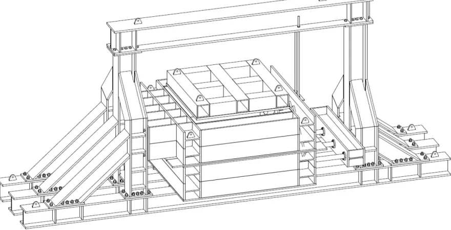
An overall view of the proposed design is shown in Figure 1. The structure comprises a large split box (internal dimensions 1.5 m x 1.5 m x 1 m) constructed from 254x254x132 UC steel sections. For each half of the box, any side will be constructed from two sections welded to-gether along the two flanges and with reinforcing gussets positioned internally. The upper half of the box is fixed by the use of a reaction frame, while the bottom half is free to move horizontally in order to shear the sample. The system which allows the movements of the bottom half consists of three long I-beams, which are firmly attached to a strong floor in the laboratory and have the role of providing runways in which machine skates can slide, allowing movement of the bot-tom half of the shear box.
The shear force is applied to the sample through four 500 kN hydraulic jacks (maintained in their position by a second reaction frame), which push the steel container in a horizontal di-rection creating a horizontal shear plane. The ver-tical load is applied by one 5 MN hydraulic jack (not shown).
The reaction frame is designed to minimise de-flections and the upper cross beam is removable to allow for filling and emptying of the container. The vertical stress is applied to the sample via a platen comprising a stiffened 30 mm thick plate designed to minimise deflections even at the maximum applied stress.
5
CONCLUSIONS
The design of a large shear box and the rationale for that design has been described in this paper.
Allowances have been made in the design for ex-pected force requirements as well as required movements to generate sufficient shear strain in the sample. The final aim of the work is to fully characterise materials with large particle sizes and investigate whether small scale analogues can ever be representative when tested.
6
ACKNOWLEDGEMENT
The valuable design assistance of Tim Lohmann and Stuart Marchand at Wentworth House Part-nership is gratefully acknowledged.
7
REFERENCES
ASTM D3080/D3080M 2011. Standard Test Method for Direct Shear Test of Soils Under Consolidated Drained Conditions. ASTM International. West Conshohocken, PA, USA.
Bareither, C.A., Benson, C.H., Edil, T.B. 2008. Com-parison of shear strength of sand backfills meas-ured in small-scale and large-scale direct shear tests, Canadian Geotechnical J.,45, 1224-1236. Barr, B.I.G., Davies, M.C.R., Jacobs, C.D 1991. A
large direct shear box - some initial results of tests on soil nails, Ground Engineering, 47-50.
Cerato, A.B., Lutenegger, A.J. 2006. Specimen Size and Scale Effects of Direct Shear Box Tests of Sands, Geotechnical Testing Journal29 (6), 507-5016.
Davies, M.C.R., Le Masurier, J.W. 1997. Soil/Nail in-teraction mechanisms from large direct shear tests. 3rd Int. Conf. on Ground Improvement
Geosys-tems.
Fu, X., Zheng, X., Lei, X., Deng, J. 2015. Using a modified direct shear apparatus to explore gap and size effects on shear resistance of coarse grained soil, Particuology23, 82–89.
Highways Agency, 2004. Manual of Contract Docu-ments for Highway Works–Volume 1 Specifica-tion 6 for Highway Works, The StaSpecifica-tionary Office, London.
Jain, S.P., Gupta, R.C. 1971. Large shear box for tests on river bed material, Indian Geotechnical Society,
98-113.
Strength. International Congress on Materials and Structural Stability. MATEC Web of Conferences Volume 11.
Krahn, T., Blatz, J., Alfaro, M., Bathurst, R.J 2007. Large-scale interface shear testing of sandbag dyke materials, Geosynthetics International 14 (2), 119–126.
Nakao, T., Fityus, S. 2008. Direct shear testing of a marginal material using a large shear box, Ge-otechnical Testing Journal31 (5), 393-403. Pedley, M.J. 1990. The performance of soil
reinforce-ment in bending and shear. Oxford University PhD thesis.
Simoni, A., Houlsby, G.T. 2006. The direct shear strength and dilatancy of sand–gravel mixtures,
Geotechnical and Geological Engineering 24,
523–549.
Sobol, E., Sas, W., Szymanski, A. 2015. Scale effect in direct shear tests on recycled concrete aggre-gate, Studia Geotechnica et Mechanica37 (2): 45-49.