City, University of London Institutional Repository
Citation
:
Casari, N., Pinelli, M., Suman, A., Kovacevic, A. ORCID: 0000-0002-8732-2242, Rane, S. and Ziviani, D. (2018). Full 3D numerical analysis of a twin screw compressor by employing open-source software. IOP Conference Series: Materials Science andEngineering, 425(1), 012017.. doi: 10.1088/1757-899X/425/1/012017
This is the published version of the paper.
This version of the publication may differ from the final published
version.
Permanent repository link:
http://openaccess.city.ac.uk/22436/Link to published version
:
http://dx.doi.org/10.1088/1757-899X/425/1/012017Copyright and reuse:
City Research Online aims to make research
outputs of City, University of London available to a wider audience.
Copyright and Moral Rights remain with the author(s) and/or copyright
holders. URLs from City Research Online may be freely distributed and
linked to.
City Research Online: http://openaccess.city.ac.uk/ [email protected]
IOP Conference Series: Materials Science and Engineering
PAPER • OPEN ACCESS
Full 3D numerical analysis of a twin screw compressor by employing
open-source software
To cite this article: Nicola Casari et al 2018 IOP Conf. Ser.: Mater. Sci. Eng. 425 012017
View the article online for updates and enhancements.
1
Content from this work may be used under the terms of theCreative Commons Attribution 3.0 licence. Any further distribution of this work must maintain attribution to the author(s) and the title of the work, journal citation and DOI.
Published under licence by IOP Publishing Ltd
Full 3D numerical analysis of a twin screw
compressor by employing open-source software
Nicola Casari, Michele Pinelli, Alessio Suman
University of Ferrara, via Saragat 1, 44122 Ferrara, ITALY
Ahmed Kovacevic, Sham Rane
City, University of London, Northampton Square, EC1V 0HB, London
Davide Ziviani
Ray W. Herrick Laboratories, Purdue University, 177 S Russell Street, West Lafayette, IN, 47907-2099, USA
E-mail: [email protected]
Abstract. The push for having more reliable and efficient positive displacement machines (both compressors and expanders) for vapor compression and power generation (e.g., ORCs) applications has moved researchers to an always more spread employment of computational fluid dynamics (CFD). In particular, twin screw compressors, because of their high efficiency compared to other compressor types, have received interest over the last years. The numerical analysis of such machines is challenging: the deforming working chambers are very difficult to be correctly replicated. The relative motion of the rotors and the variation of the gaps during machine operation are few of the major difficulties in implementing reliable CFD models. A custom mesh generation algorithm is therefore often required for sumulating the machine operation.
In this work, SCORG-V5.2.2 was used to generate the meshes of the deforming domain around rotating parts of the machines. The open-source software OpenFOAM-v1606+ is then employed to compute the flow field associated with the operation of the twin screw. The coupling of the two tools has been carried out in this work, applying the methodology to a twin screw machine.
1. Introduction
2
1234567890‘’“”
International Conference on Screw Machines 2018 IOP Publishing IOP Conf. Series: Materials Science and Engineering 425 (2018) 012017 doi:10.1088/1757-899X/425/1/012017
attention from the researchers, making screw compressors to comprise the majority of all positive displacement compressors in operation, as reported by [5, 6]. Either in compressor or expander configuration, the reliability and compactness they ensure are appreciated by designers and operators. Their cost-effectiveness is definitely the feature that makes this machine so spread, as suggested by [6] and [7].
The diffusion of such machines has pushed researchers to look into such devices, in order to improve their efficiency. A useful tool for the prediction of flow behaviour and performance is the Computational Fluid Dynamics (CFD) analysis, see [8, 9, 10, 11]. The experimental campaign may be very challenging, due to the geometrical complexity and the compatibility of the instrumentation. The numerical approach may be the only way to investigate the potential behaviour of the machine with new fluids without major changes to be carried out. Nonetheless, the complexity of the simulation has brought about the birth and the application of several numerical techniques. A brief yet comprehensive review of the possible methods for the simulation of PD machines that are usually available with common software is reported in [12]. Among the several issues that derives from the numerical approach applied to these machines, the high mesh deformation asks for extra care during the mesh generation and motion evolution phases. The deforming working chambers make the fluid domain to span from the volume of O(mm3) to the O(µm3) in the gap areas. The computational grid must follow this evolution, bearing such stretch without losing the quality, to correctly replicate the flow field evolution.
To tackle the mesh motion problem, different approaches have been developed over the years. Particularly, if referring to the review in [12], the Key Frame Remeshing algorithm and the Mesh Adaption - Dynamic Remeshing, are only some of the techniques that may be employed. The main idea underlying these two methods is that most of the general-purpose dynamic mesh solvers smooth the pre-defined boundary displacement inside the domain in such a way that the internal mesh is the solution of the boundary motion. The mesh is recomputed (globally or locally, according to the strategy chosen) if the cell quality falls below a certain threshold. A different approach is considered if one makes use of the overset grids, as reported for example by [13], or of the Immersed Boundary Method (IBM), see [14]. In the first case, the mesh deformation is not solved, and the domain motion is accounted for by defining different regions corresponding to different areas involved in the deformation. Such regions are rigidly displaced, passing from the actual time step to the next: the relative motion is accounted for by checking the overlapping cells. Fluxes between the two regions are exchanged only if a certain number of cells is overlapping. For what concerns the IBM, the motion is considered by modifying the source term in the flow equations. All the above-mentioned methods suffer from major drawbacks. Remeshing-based motion solvers are generally time-consuming and can easily lead to continuity errors, as suggested by [15]. Overset approach suffers from the same problem. IBM is poor in solving the boundary layer region, due to the non-aligned edges with respect to the wall.
3
controlled. The ”Custom Predefined Mesh Generation Algorithm” is used in this work [16]. SCORG-v5.2.2 was used for generating the set of meshes and OpenFOAM-v1606+ for the flow field solution. A new motion solver has been developed to force the mesh to pass through the control points, for modeling the rotor evolution.
2. Methodology
In this section the algorithm developed to make the flow solver to account for the mesh motion will be presented and applied on a simplified twin screw. The mesh generation will be discussed as well.
2.1. Geometry
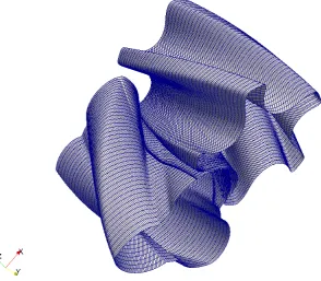
The geometry of the machine has been generated with the SCORG software itself. A machine with a mild warp angle (i.e. 100◦) has been considered. Also, the rotors are quite short (aspect ratio, i.e. length-to-diameter ratio, around 0.7) with respect to the more commonly employed machines (i.e. roughly 1.6). These simplifications have been introduced in order to have higher cell quality, due to the milder warpage of the thread, and a low number of grid elements due to the smaller domain. By employing these expedients, a simpler geometry yet representative of the screw operation has been generated. The so-obtained machine, together with a closer view of the rotors, is reported in Fig. 1.
The spread of the twin-screw type machine has been achieved thanks to the improvements in low-cost, high-precision manufacturing techniques. In light of this, a feature that is of paramount importance when dealing with this type of devices is the gap size. In this work the clearance between rotor and casing has been chosen to be equal to 60µm like the interlobe gap. The axial gap has been chosen equal to 5µm.
2.2. Mesh Generation
In this paper, the deforming grid of the twin screw machine is generated using algebraic transfinite interpolation treated as an initial mesh upon which Elliptic Partial Differential
[image:5.595.89.513.538.711.2](a)Overall view of the machine investigated in this work(b)Particular: upper view of the male and female rotors
4
1234567890‘’“”
International Conference on Screw Machines 2018 IOP Publishing IOP Conf. Series: Materials Science and Engineering 425 (2018) 012017 doi:10.1088/1757-899X/425/1/012017
Equation (PDE) of the Poissons form is solved [17]. The resulting differential grid has highly improved cell quality and distribution. The initial algebraic grid obtained via transfinite interpolation is smoothed out using system of differential equation. The source function for such equations have been simplified to use only two input parameters based on the test function given by [18]. Particularly, the Radial Bias Factor and the Radial Bias Intensity have been added, for the inflation layer control. On the top of that, weighting coefficients have been introduced for an improvement of the orthogonality of the grid. The grid constraint (orthogonality, warpage, skewness,...) the generated mesh must satisfy have been defined in compliance with the threshold employed by the most used CFD tools. This does not automatically entails the compliance with the new tested CFD software (i.e. OpenFOAM) as described in section 3. In addition, a special procedure completely smooths the transition of the partitioning rack curve between the two rotors thus improving grid node movement and robustness of the CFD solver. A sample analysis of an oil injected twin screw compressor using the new Elliptic PDE grids has been presented [19] to compare the improvements in grid quality factors in the regions of importance such as interlobe space, radial tip and core of the rotors. A significant improvement in the grid quality and robustness of numerical solver with higher order schemes has been obtained with this differential implementation of the deforming mesh. The conforming of the two grids at the interface is such that the PDE mesher is used in a selective interlobe area of the mesh to convert the rack curve into a smooth transitioning curve across the specified number of angular positions of the rotor. This results into a gradually changing partition between the two O grids of the male and female rotors.
The rotor mesh must be coupled with the suction and the discharge ports. The mesh of such ports, has been generated with the OpenSource software cfMesh [20]: a cartesian cut-cell grid has been generated. The rotating domain is divided from the port static one by means of ACMI (arbitrary coupling mesh interface). Since the rotor axial patches do not completely overlap the ports, the interface has to automatically detect whether fluxes must be exchanged (when fluid-fluid cells are exposed) or not (e.g. when the interface is between fluid and solid cell).
Once the mesh is generated, it must be exported to OpenFOAM readable format. This feature is not yet available into SCORG. For the current analysis, the mesh translation was done via ANSYS-CFX and ANSYS-FLUENT. The rotors zone is exported as a whole, being recognized as a cellZone by OpenFOAM, thanks to the conformal interface. This expedient avoids conservation issues that may affect AMI interfaces [21]. This problem may be quite relevant in applications like the one presented in this work, since the velocity vector is highly tangential with respect to the interface, especially in the interlobe area. The resulting mesh is composed of roughly 1,700,000 cells. The rotor zone is composed of 200,000 hexaedral cells.
2.3. Numerical Analysis
As above mentioned, the twin-screw operation entails the rotors motion. Such rotation causes the deformation of the computational domain and thus the mesh should accomodate such displacement. The strategy adopted in this work is to generate a structured computational mesh for an initial position, as reported in the section 2.2. At this point a user-defined number of grids per gate-rotor pitch is generated and written in separate files. Each of the file contains the control points (coordinates) through which the computational nodes has to pass during the machine operation. This entire procedure is carried out within the SCORG-v5.2.2 framework. In the current work, a set of 50 files per groove are generated, meaning there are 50 points through which a moving mesh node has to pass to cover a pitch.
5
xi,f inal =αxi,AG+ (1−α)xi,N G (1)
where the subscript AG represents the actual grid file and NG is for the next grid file. AG and NG are the files written by SCORG containing the node postion at the two time instant we are interpolating among. xi represents the position of the node at the corresponding grid file
(when the subscript AG or NG is reported). This algorithm has been added to the mesh motion libraries available in OpenFOAM-v1606+ and OpenFOAM-v1712.
The case was simulated under the boundary conditions reported in Table 1. The high-Re k- model has been used for the performance evaluation with standard wall functions. It must be remarked here that the rotational speed of the two rotors is different due to the different number of threads. The algorithm proposed handles this difference automatically, asking the user to provide only the revolutions per minute of the male rotor. The rotational frequency of the female rotor can be easily derived from the number of threads ratio: in this work the female rotor has 4 threads and the male rotor has 3 threads. The diameter of the male rotor is 127.4 mm and the female one is equal to 120.4 mm.
[image:7.595.147.442.474.731.2]Besides, the number of grooves has to be provided in order to compute the time it takes to cover one pitch for the male rotor. This allows the automatic scaling of the time step in order to satisfy the maximum CFL condition, to have a stable simulation. In this work the maximum CFL allowed to have stable simulation is bounded to 1. This limit is required to avoid the spikes of pressure/temperature that are outlined in section 3 . The solver employed in this work is rhoPimpleDyMFoam, which belongs to the compressible set of solver that comes with the software OpenFOAM-v1606+. This solver employs PISO algorightm [22] with inner integration performed with SIMPLE strategy [23]. The implementation in the OpenFOAM framework is described in [24] or [25]. This solver can automatically take into account any mesh motion input given by the user. In this work, the developed algorithm is enclosed in a library read by the
6
1234567890‘’“”
[image:8.595.72.536.133.445.2]International Conference on Screw Machines 2018 IOP Publishing IOP Conf. Series: Materials Science and Engineering 425 (2018) 012017 doi:10.1088/1757-899X/425/1/012017
Table 1. Boundary conditions for the computation of the flow field
Quantity Value
p0 101,000 Pa
T0 300 K
Turbulence intensity 1 % Inlet
Turbulence mixing length 0.0021 m
Fixed Walls T adiabatic
ωmale 8000 rpm
Rotating Walls
T adiabatic
Outlet p 131,000 Pa
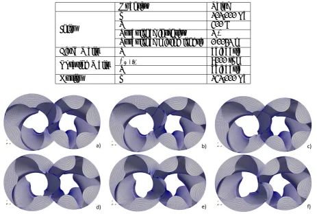
Figure 3. Evolution of the mesh during the CFD analysis, particular of one pitch.
dynamicMeshDict, that is the dictionary that asks for any mesh motion input. The library is dynamically linked during the compilation is such a way that is location insensitive and can be stored anywhere in the hard drive (i.e. it is not necessary to keep the files in the same directory of the case). The simulation run fully parallel thanks to the open MPI library. Extra-care should be taken when decomposing the domain, due to the presence of non-conformal interfaces at the inlet and outlet ports. To enforce mass conservation, both the sides of the ACMI interface are forced to stay on the same processor. This feature comes with the standard installation of OpenFOAM.
3. Results
The evolution of the grid position as provided by the motion solver algorithm is reported in Fig. 3. The high deformation of the conformal interface can be noticed.
The Rotor-To-Casing non-conformal approach cannot be used in this case. If the mesh was generated with this approach, the Rotor-Casing ACMI interface should communicate with two different neighbours: the discharge port and the interface among the two rotors. This is not supported by the ACMI implementation in OpenFOAM.
7
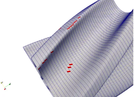
Figure 4. Faces having a wrong oriented normal
reported in Fig. 5. These spikes have occurred for all the tested numerical schemes both first and second order accurate. Limiting the gradients was not effective in this case, and the only solution was to lower the maximum time step of the simulation. This is probably related to the fact that few wrong oriented faces arise as a consequence of the rotation, as reported in Fig. 4. This seems not to be an issue when dealing with Courant number lower than one, but give problems when the time step exceeds such threshold. Further investigations are required to fix this problem.
The implementation presented in this work handles automatically this variable time step, as described in section 2.3. Future work is required to improve the robustness of the solver for higher time step. Spikes in temperature may be avoided by bounding the temperature in the rotor zone. This ”clipping” is of help in stabilizing the simulation, but should be avoided since it acts as a source or sink of energy, causing a mismatch in the energy imbalance. Furthermore, it has been found that the artificial bounding is not effective if the time step is not reduced accordingly (as suggested above).
An example of the results that can be obtained if the CFL<1 condition holds is reported in Fig. 6, where the pressure fields on the male rotor is reported. The simulation has been carried out with the boundary conditions reported in Tab. 1. The pattern is in agreement with the expectations: the chamber in communication with the discharge port shows the highest pressure values. Immediately downstream the thread head, a slightly low pressure area can be detected as a result of the gap presence. The fluid expands through the gap, passing frome the high pressure groove to the lower one. Such pressure difference is then recovered inside the chamber. With the mesh used in this work, the y+value required wall functions to be used. Particularly, a minimum y+ of 50 has been found, whereas the average is around 120. The minimum value of the y+ happens in the interlobe gap.
4. Conclusion
In this work, the simulation of a simplified twin screw compressor has been carried out. The simplified geometry was chosen in order to prove the capability of the algorithm developed in simulating the operation of a positive displacement machine. The simplifications reside in the low warp angle and the short axial dimension, whereas the gap size is very close to an actual machine.
8
1234567890‘’“”
[image:10.595.107.511.114.440.2]International Conference on Screw Machines 2018 IOP Publishing IOP Conf. Series: Materials Science and Engineering 425 (2018) 012017 doi:10.1088/1757-899X/425/1/012017
Figure 5. Temperature spike originated in the gap between thread head and casing on the female rotor
[image:10.595.194.417.493.688.2]9
files has been generated by SCORG, a propretary software, and OpenFOAM, an open-source toolkit, was employed for solving the flow field. The coupling was carried out successfully in the case of single rotor domain, having a conformal interface in the interlobe area.
The dynamic mesh library here developed is able to make the mesh into OpenFOAM to move according to the output files generated by SCORG. The technique proposed is suitable for the simulation of positive displacement machines, not demanding for remeshing and thus not violating the space conservation law (entailing the non-conservativeness of the mass).
The application of this algorithm to a real twin-screw compressor, the comparison of the results with other CFD software and the validation is to be considered as a next step in this work.
5. Acknowledgement
The research was partially supported by the Italian Ministry of Economic Development within the framework of the Program Agreement MSE-CNR ”Micro co/tri generazione di Bioenergia Efficiente e Stabile (Mi-Best)”.
References
[1] Tassou S and Qureshi T 1998International Journal of Refrigeration 2129–41
[2] Ziviani D, Gusev S, Lecompte S, Groll E, Braun J, Horton W T, van den Broek M and De Paepe M 2016
Applied Energy 181155–170
[3] Quoilin S, Declaye S, Tchanche B F and Lemort V 2011Applied thermal engineering312885–2893 [4] Landelle A, Tauveron N, Haberschill P, Revellin R and Colasson S 2017Applied Energy 2041172–1187 [5] Stosic N, Smith I K and Kovacevic A 2002 A twin screw combined compressor and expander for CO2
refrigeration systems
[6] Lemort V, Guillaume L, Legros A, Declaye S and Quoilin S 2013 Proceedings of the 3rd International Conference on Microgeneration and Related Technologies
[7] Tang H, Wu H, Wang X and Xing Z 2015Energy90631–642
[8] Kovacevic A, Stosic N and Smith I 2007 Screw Compressors: Three Dimensional Computational Fluid Dynamics and Solid Fluid Interaction vol 46 (Springer Science & Business Media)
[9] Suman A, Ziviani D, Gabrielloni J, Pinelli M, De Paepe M and Van Den Broek M 2016Energy Procedia101
750–757
[10] Morini M, Pavan C, Pinelli M, Romito E and Suman A 2015Applied Thermal Engineering 80132–140 [11] Chang J C, Chang C W, Hung T C, Lin J R and Huang K C 2014Applied Thermal Engineering731444–1452 [12] Casari N, Suman A, Ziviani D, van den Broek M, De Paepe M and Pinelli M 2017 Energy Procedia 129
411–418
[13] Suman A, Randi S, Casari N, Pinelli M and Nespoli L 2017Energy Procedia 129403–410 [14] Mittal R and Iaccarino G 2005Annu. Rev. Fluid Mech.37239–261
[15] Rane S, Kovacevic A, Stosic N and Kethidi M 2013International Journal of Refrigeration 361883–1893 [16] Rane S 2015 Grid generation and CFD analysis of variable geometry screw machines Ph.D. thesis City
University London
[17] Thompson J F, Soni B K and Weatherill N P 1998Handbook of grid generation (CRC press) [18] Knupp P and Steinberg S 2002Fundamentals of grid generation(CRC press)
[19] Rane S and Kovacevic A 2017Advances in Engineering software 10738–50 [20] Jureti´c F 2015Zagreb, Croatia
[21] Buratto C, Casari N, Aldi N, Pinelli M and Suman A 2016 Cfd analysis of non-newtonian fluid processing pump 13thOpenFOAM Workshop, Guimaraes
[22] Issa R I 1986Journal of computational physics 6240–65
[23] Patankar S 1980Numerical heat transfer and fluid flow (CRC press)
[24] Jasak H 1996 Error analysis and estimation for the finite volume method with applications to fluid flows.
(Imperial College London (University of London))