Iteratively Decoded Variable Length Space-Time Coded Modulation
S. X. Ng and L. Hanzo
School of ECS, University of Southampton, SO17 1BJ, UK.
Tel: +44-23-8059 3125, Fax: +44-23-8059 4508
Email:
{
sxn,lh
}
@ecs.soton.ac.uk, http://www-mobile.ecs.soton.ac.uk
Abstract – An Iteratively Decoded Variable Length Space
Time Coded Modulation (VL-STCM-ID) scheme capable of simultaneously providing both coding and iteration gain as well as multiplexing and diversity gain is proposed. Non-binary unity-rate precoders are employed for assisting the iterative decoding of the VL-STCM-ID scheme. The discrete-valued source symbols are first encoded into variable-length codewords that are mapped to the spatial and temporal do-mains. Then the variable-length codewords are interleaved and fed to the precoded modulator. More explicitly, the proposed VL-STCM-ID arrangement is a jointly designed iteratively decoded scheme contriving source coding, chan-nel coding, modulation and spatial diversity/multiplexing. As expected, the higher the source correlation, the higher the achievable performance gain of the scheme becomes. Furthermore, the performance of the VL-STCM-ID scheme is more than 14 dB better than that of the Fixed Length STCM (FL-STCM) benchmarker at a source symbol error ratio of10−4.
1. INTRODUCTION
Shannon’s separation theorem stated that source coding and channel coding is best carried out in isolation [1]. However, this theorem was formulated in the context of potentially infinite-delay, lossless entropy-coding and infinite block length chan-nel coding. In practise, real-time wireless audio/video com-munications systems do not meet these ideal hypotheses. Ex-plicitly, the source encoded symbols often remain correlated, despite the lossy source encoder’s efforts to remove all redun-dancy. Furthermore, they exhibit unequal error sensitivity. In these circumstances, it is often more efficient to use jointly de-signed source and channel encoders.
The wireless communication systems of future generations are required to provide reliable transmissions at high data rates in order to offer a variety of multimedia services. Space time coding schemes, which employ multiple transmitters and re-ceivers, are among the most efficient techniques designed for providing high data rates by exploiting the high channel ca-pacity potential of Multiple-Input Multiple-Output (MIMO)
The financial support of the EPSRC, Swindon UK and the EU under the auspices of the PHOENIX and NEWCOM projects is gratefully acknowl-edged.
channels [2, 3]. More explicitly, Bell-lab’s LAyered Space Time architecture (BLAST) [4] was designed for providing full transmitter-multiplexing gain, while Space Time Trellis Codes (STTC) [5] were designed for providing full transmitter-diversity gain.
In this contribution, we describe a jointly designed source coding and Space Time Coded Modulation (STCM) scheme, where two dimensional (2D) Variable Length Codes (VLCs) are transmitted by exploiting both the spatial and temporal do-mains. More specifically, the number of activated transmit antennas equals the number of symbols of the corresponding VLC codeword in the spatial domain, where each VLC code-word is transmitted during a single symbol period. Hence, the transmission frame length is determined by the fixed number of source symbols and therefore the proposed Variable Length STCM (VL-STCM) scheme does not exhibit synchronisation problems and does not require the transmission of side infor-mation. Additionally, the associated source correlation is con-verted into an increased product distance, hence resulting in an increased coding gain. Furthermore, the VL-STCM scheme is capable of providing both multiplexing and diversity gains with the aid of multiple transmit antennas.
It was shown in [6] that a binary unity-rate precoder can be serially concatenated with Trellis Coded Modulation (TCM) [7] for the sake of invoking iterative detection and hence for attain-ing iteration gains. Since VL-STCM also belongs to the TCM family, we further develop the VL-STCM scheme for attaining additional iteration gains by introducing non-binary unity-rate precoders between the variable-length space-time encoder and the modulator. The Iteratively Decoded (ID) VL-STCM (VL-STCM-ID) scheme achieves a significant coding/iteration gain over both the non-iterative VL-STCM scheme and the Fixed Length STCM (FL-STCM) benchmarker.
2. SPACE TIME CODING OVERVIEW
Let us consider a MIMO system employingNt transmit
an-tennas andNrreceive antennas. The signal to be transmitted
from transmit antennam,1 ≤m ≤Nt, at the discrete time
indextis denoted asxm[t]. The signal received at antennan,
1≤n≤Nr, and at time instanttcan be modelled as:
rn[t] =
p
Es Nt X
m=1
hn,m[t]xm[t] +wn[t], (1)
where Es is the average energy of the signal constellation,
hn,m[t] denotes the flat-fading channel coefficients between
transmit antenna m and receive antenna nat time instant t, while wn[t] is the Additive White Gaussian Noise (AWGN)
having zero mean and a variance ofN0/2per dimension. The
amplitude of the modulation constellation points is scaled by a factor of√Es, so that the average energy of the constellation
points becomes unity and the expected Signal-to-Noise Ratio (SNR) per receive antenna is given byγ =NtEs/N0[8]. Let
us denote the transmission frame length asT symbol periods and define the space-time encoded codeword as an (Nt×T
)-dimensional matrixCformed as:
C =
c1[1] c1[2] . . . c1[T] c2[1] c2[2] . . . c2[T]
..
. ... . .. ...
cNt[1] cNt[2] . . . cNt[T]
, (2)
where the tth column c[t] = [c1[t] c2[t]. . . cNt[t]]
T is the
space-time symbol transmitted at time instant t and themth rowcm = [cm[1]cm[2]. . . cm[T]] is the space-time symbol
transmitted from antennam. The signal transmitted at time instanttfrom antennam, which is denoted asxm[t]in
Equa-tion 1, is the modulated space-time symbol given byxm[t] =
f(cm[t])wheref(.)is the modulator’s mapping function. The
Pair-Wise Error Probability (PWEP) of erroneously detecting
Einstead ofCis upper bounded at high SNRs by [5, 9]:
p(C→E) ≤ 1
2
E
s
4N0
−EH·Nr
(EP)−Nr, (3)
whereEH is referred to as the effective Hamming distance,
which quantifies the transmit diversity order andEP is termed
as the effective product distance [5], which quantifies the cod-ing advantage of a space-time code.
It was shown in [10] that a full-transmitter-diversity STTC scheme having the minimum decoding complexity can be sys-tematically designed based on two steps. The first step is to design a block code, while the second step is to transmit the block code diagonally across the space-time grid. The mech-anism of the diagonal transmission across the space-time grid will be exemplified in Section 4 in the context of Figure 2. The Hamming distance and the product distance of a block
code can be preserved, when the block code is transmitted di-agonally across the space-time grid. Hence, a full-transmitter-diversity STTC scheme can be realised, when the Hamming distance of the block code used by the STTC scheme equals to the number of transmitters. Based on the same principle, a joint source coding and STTC scheme can be systematically designed by first designing a 2D VLC and then transmitting the 2D VLC diagonally across the space-time grid. As mentioned above [10], this allows us to achieve a transmitter-diversity or-der, which is identical to the Hamming distance of the 2D VLC plus a coding advantage quantified by the product distance of the 2D VLC, as well as a multiplexing gain, provided that the number of possible source symbolsNsis higher than the
num-ber of modulation levelsM.
Let us now commence our detailed discourse on the pro-posed VL-STCM-ID scheme in the following sections.
3. TWO-DIMENSIONAL VLC DESIGN
Consider for example a source havingNs= 8possible discrete
values and let thelth value be represented by a symbolsl=l
forl∈ {1,2, . . . , Ns}. Furthermore, assume that the source is
correlated such that the source symbol occurrence probability is given by:
P(sl+1) = 0.6P(sl), (4)
andPNs
l=1P(s
l) = 1. Hence, the source symbols1 has the
highest occurrence probability ofP(s1) = 0.406833and the source symbols8has the lowest occurrence probability ofP(s8) = 0.011389. Let us now consider a 2D VLC codeword matrix,
VV LC, which encodes theseNs= 8possible source symbols
usingNt= 3transmit antennas and BPSK modulation as
fol-lows:
VV LC =
x 1 x 0 x 0 1 1
x x 0 x 1 1 0 1
0 x x 1 1 x 1 0
, (5)
where each column of the (3×8)-dimensional matrixVV LC
corresponds to the specific VLC codeword conveying a par-ticular source symbol and the elements in the matrix denoted as 0 and 1 represent the BPSK symbols to be transmitted by theNt = 3transmit antennas, while ‘x’ represents ‘no
trans-mission’. ‘No transmission’ implies that the corresponding transmit antenna sends no signal. Let thelth source symbol
slbe encoded using themth column of theVV LCmatrix seen
in Equation 5. Hence, the source symbols1 is encoded into an Nt-element codeword using the first column ofVV LC in
Equation 5, namely[x x0]T, where the first and second trans-mit antennas are in the ‘no transmission’ mode, while the third antenna transmits an ‘active’ symbol represented by the binary value ‘0’. If L(sl)is the number of ‘active’ symbols in the
de-fine the average codeword length of the 2D VLC as:
Lave=
Ns X
l=1
P(sl)L(sl), (6)
where we haveLave= 1.233bit/VLC codeword for this
sys-tem according to Equations 4 and 5. The corresponding BPSK
f
(1) =
−
A
f
(x) = 0
f
(0) =
A
−
A
0
A
A
=
q
Nt [image:3.595.322.565.446.603.2]Lave
Figure 1: The signal mapper of the VL-STCM. signal mapper is characterised in Figure 1, where the ‘no trans-mission’ symbol is actually represented by the origin of the Eu-clidean space, i.e. we havef(x) = 0, wheref(.)is the map-ping function. Since the ‘no transmission’ symbol is a zero energy symbol, the amount of energy saving can be computed from:
A2= Nt
Lave
, (7)
where we haveA2 = 3/1.233 = 2.433, which is equivalent
to20 log(A) = 3.86dB. Hence, more transmitted energy is saved, when there are more ‘no transmission’ symbols in a VLC codeword. Therefore, the columns of the matrixVV LC
in Equation 5, which are the VLC codewords, and the source symbols are specifically arranged, so that the more frequently occurring source symbols are assigned to VLC codewords hav-ing more ‘no transmission’ components, in order to save trans-mit energy. The energy saved is then reallocated to the ‘active’ symbols for the sake of increasing their minimum Euclidean distance, as shown in Figure 1.
The design of the 2D VLC scheme can be summarised in the following three steps:
1. Search for all possible VLC codeword matrices, which have the maximum achievable minimum Hamming dis-tance EHmin and product distance EPmin values for
each pair of the VLC codewords at a givenNs andNt
combination. Note that attaining a higherEHminis given
more weight thanEPminsinceEHmin, is more
domi-nant in the PWEP of Equation 3.
2. From the resultant VLC matrices, choose that specific one, which has the highest number of ‘no transmission’ symbols at the givenEHminandEPmincombination.
3. Assign the more frequently occurring source symbols to the VLC codewords having more ‘no transmission’ com-ponents.
Additionally, we note that the correlation of the source only affects the specific mapping of the source symbols to the 2D
VLC codewords, but not the search for the best 2D VLC itself, which takes place during steps 1 and 2. As in the conventional 1D VLC, the higher the source correlation, the lower the av-erage codeword lengthLaveof the 2D VLC. Hence, a higher
power saving can be obtained, when the source is more cor-related, since the amount of energy saving is given by Equa-tion 7, whereNtis fixed. The 2D VLC matrix seen in
Equa-tion 5 was designed based on the above three steps and the cor-responding minimum Euclidean distance of the BPSK constel-lation points seen in Figure 1 becomes identical toA= 1.56. The minimum Hamming distance isEHmin = 2, as can be
verified by counting the number of different symbol positions of all the columns in Equation 5. Hence a transmit-diversity of orderEHmin = 2can be achieved instead of three, when Nt = 3transmit antennas are employed for transmitting the
Nt-element 2D VLC codewords denoted asv= [v1. . . vNt]
T
in Figure 2. On the other hand, the minimum product distance
EPmincan be computed based on Equation 5 and the signal
mapper of Figure 1. Explicitly, the corresponding minimum product distance is found to beEPmin= 5.92, which is
com-puted as [10]:
EPmin = min
1≤s<˜s≤Ns Y
m∈ξ
|f(vm)−f(˜vm)|
2
, (8)
whereξis the specific VLC codeword component of Figure 2 mapped to transmit antenna indexmassociated withvm6= ˜vm
for 1 ≤ m ≤ Nt, while [v1. . . vNt]
T and[˜v
1. . .˜vNt]
T are
two VLC codewords conveying the source symbolss and˜s, respectively.
4. VL-STCM TRANSMITTER
Mapper Mapper
Mapper
Mapper VLC
Encoder Modulator
S1
S2
s[t]
Sp−q
S3
Sp
p=PNt
j=1(j−1) ; q=Nt−2
vNt[t] v3[t]
v2[t]
v1[t] c1[t]
c2[t]
c3[t]
cNt[t]
x1[t]
x2[t]
x3[t]
xNt[t]
Figure 2: Block diagram of the VL-STCM transmitter.
The block diagram of the VL-STCM transmitter is illus-trated in Figure 2. As seen in Figure 2, a VLC codeword
v[t] = [v1[t]v2[t]. . . vNt[t]]
T is assigned to each of the source
symbolss[t]generated by the source at time instant t, where
s[t] ∈ {1, . . . , Ns} andNs denotes the number of possible
source symbols. Each component of the VLC codewordv[t]
c : [c1c2c3] T
S : [S1S2S3]
[ 0 1 0 2 0 2 1 1 ] 0 : [ x 0 0 ]
[ 3 4 3 5 3 5 4 4 ] 1 : [ x 0 1 ]
[ 6 7 6 8 6 8 7 7 ] 2 : [ x 0 x ]
[ 0 1 0 2 0 2 1 1 ] 3 : [ x x 0 ]
[ 3 4 3 5 3 5 4 4 ] 4 : [ x x 1 ]
[ 6 7 6 8 6 8 7 7 ] 5 : [ x x x ]
[ 9 10 9 11 9 11 10 10 ] 6 : [ 0 x 0 ]
[12 13 12 14 12 14 13 13 ] 7 : [ 0 x 1 ]
[15 16 15 17 15 17 16 16 ] 8 : [ 0 x x ]
[ 0 1 0 2 0 2 1 1 ] 9 : [ x 1 0 ]
[ 3 4 3 5 3 5 4 4 ] 10: [x 1 1 ]
[ 6 7 6 8 6 8 7 7 ] 11: [x 1 x ]
[18 19 18 20 18 20 19 19 ] 12: [1 1 0 ]
[21 22 21 23 21 23 22 22 ] 13: [1 1 1 ]
[24 25 24 26 24 26 25 25 ] 14: [1 1 x ]
[18 19 18 20 18 20 19 19 ] 15: [1 x 0 ]
[21 22 21 23 21 23 22 22 ] 16: [1 x 1 ]
[24 25 24 26 24 26 25 25 ] 17: [1 x x ]
[ 9 10 9 11 9 11 10 10 ] 18: [0 1 0 ]
[12 13 12 14 12 14 13 13 ] 19: [0 1 1 ]
[15 16 15 17 15 17 16 16 ] 20: [0 1 x ]
[18 19 18 20 18 20 19 19 ] 21: [1 0 0 ]
[21 22 21 23 21 23 22 22 ] 22: [1 0 1 ]
[image:4.595.65.295.72.543.2][24 25 24 26 24 26 25 25 ] 23: [1 0 x ]
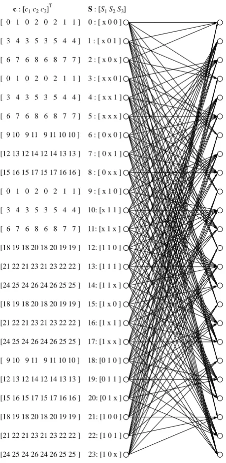
Figure 3: The trellis of VL-STCM when invoking the 2D VLC of Equation 5. For the list of codewords see Table 1.
of the columns in the VLC matrix of Equation 5. As por-trayed in Figure 2, the VLC codewordv[t]is transmitted diag-onally across the space-time grid with the aid of appropriate-length shift registers denoted asSkin Figure 2, where we have
k ∈ {1,2, . . . ,PNt
j=1(j−1)}. As we can see from Figure 2,
the codewordv[t] = [v1[t]v2[t] . . . vNt[t]]
Tis transmitted
us-ingNttransmit antennas, where themth element of each VLC
codeword, for1≤m≤Nt, is delayed by (m−1) shift register
cells, before it is transmitted through themth transmit antenna. Hence, theNtnumber of components of each VLC codeword
are transmitted on a diagonal of the space-time codeword
ma-Index c Index c Index c
[image:4.595.320.578.72.196.2]0 [ 0 x x ]T 9 [ 0 0 x ]T 18 [ 0 1 x ]T 1 [ 0 x 1 ]T 10 [ 0 0 1 ]T 19 [ 0 1 1 ]T 2 [ 0 x 0 ]T 11 [ 0 0 0 ]T 20 [ 0 1 0 ]T 3 [ 1 x x ]T 12 [ 1 0 x ]T 21 [ 1 1 x ]T 4 [ 1 x 1 ]T 13 [ 1 0 1 ]T 22 [ 1 1 1 ]T 5 [ 1 x 0 ]T 14 [ 1 0 0 ]T 23 [ 1 1 0 ]T 6 [ x x x ]T 15 [ x 0 x ]T 24 [ x 1 x ]T 7 [ x x 1 ]T 16 [ x 0 1 ]T 25 [ x 1 1 ]T 8 [ x x 0 ]T 17 [ x 0 0 ]T 26 [ x 1 0 ]T
Table 1: The space-time codeword table.
trix of Equation 2. Since the VLC codewords are encoded di-agonally, the space-time coded symbol cm[t] transmitted by
themth antenna,1 ≤m ≤ Nt, at a particular time-instantt
is given bycm[t] =vm[t−m+ 1]. Hence, for this specific
case each element of the space-time codeword matrix of Equa-tion 2 is given bycm[t] =vm[t−m+ 1], while the transmitted
signal is given byxm[t] =f(cm[t]) =f(vm[t−m+ 1])for
1≤m≤Nt.
Note that originally there were onlyNs = 8 legitimate
2D-VLC codewords in Equation 5. However, after these VLC codewords are diagonally mapped across the space-time grid using the shift registers shown in Figure 2, there is a total of
¯
MNt = 33 = 27legitimate space-time codewords, whereM¯ is the number of possible symbols in each position of the 2D VLC codewords. Note however that the actual number of le-gitimate space-time codewords can be less thanM¯Nt. The cor-responding trellis diagram of the proposed VL-STCM scheme is depicted in Figure 3. TheNt= 3-element space-time
code-word seen in Figure 2 is given by c = [c1 c2 c3]T and the
relationship between the 27 codeword indices shown in Fig-ure 3 andcis defined in Table 1. The trellis states are defined by the contents of the shift register cellsSkshown in Figure 2,
which are denoted byS= [S1S2S3]. For example, the state
S= 0is denoted as[x0 0]in the trellis diagram of Figure 3. Note that each shift register cell may holdM¯ = 3possible val-ues, namely{0,1,x}in conjunction with the VL-STCM based on Equation 5. However, the number of legitimate trellis states can be less thanM¯p, wherep=PNt
j=1 = 3is the total
num-ber of shift registers. Hence, in our specific case there are only 24 legitimate trellis states out of theM¯p = 27possible trellis
states, which is a consequence of the constraints imposed by the 2D VLC of Equation 5.
5. VL-STCM-ID TRANSCEIVER
In order to invoke iterative detection and hence attain iteration gains as a benefit of the more meritoriously spreadextrinsic
information, we introduce a symbol-based interleaver and a non-binary unity-rate precoder for each of theNt= 3transmit
inter-Mapper
Mapper
Demodulator
Demapper Soft MIMO
Channels
Mapper Decoder
MAP
Decoder MAP
Decoder MAP Encoder
VLC VL−STCM
MAP
Decoder
D
D
D
D πs
πs
π−1
s
πs
π−1
s
πs
π−1
s
Modulator
˜ u1[t]
˜ u2[t]
˜ u3[t]
D
D VL-STCM Encoder
πs
πs
˜ c1[t]
˜ c2[t]
˜ c3[t]
˜ s[t]
ˆ s[t] y1[t]
y2[t]
x3[t]
x2[t]
x1[t]
u1[t]
u2[t]
u3[t]
c1[t]
c2[t]
c3[t]
v3[t]
v2[t]
v1[t]
[image:5.595.64.566.74.177.2]s[t]
Figure 4: The VL-STCM-ID transceiver employingNt = 3transmit andNr = 2receive antennas. The notation(˜.)and(ˆ.)
indicates theextrinsic/a prioriprobability and the hard decision estimate of(.), respectively.
leaved and encoded by a non-binary unity-rate precoder, be-fore feeding them to the mapper. It was found that without the recursive feedback assisted non-binary precoder, the iterative detection aided VL-STCM-ID was unable to outperform the lower-complexity non-iteratively decoded VL-STCM scheme. By contrast, a simple single-cell non-binary precoder invoked for each of the transmit antennas did allow us to achieve a significant iteration gain. The non-binary precoder employs a modulo-M¯ adder, where againM¯ = 3is the number of dif-ferent symbols in the VLC space-time codeword and we have
cm[t] ∈ {0,1,x}. Accordingly, this single-cell precoder
pos-sessesM¯ = 3trellis states.
At the receiver, the symbol-based MAP algorithm [11] is used by both the VL-STCM decoder and the unity-rate de-coder. As we can see from Figure 4, the MAP decoder of the VL-STCM scheme benefits from thea prioriinformation of the space-time codeword c[t] = [c1[t]c2[t]c3[t]]T provided
by the demodulator as well as from thea prioriinformation of the source symbolss[t]quantified in terms of their differ-ent probabilities. Furthermore, each of the Nt = 3
unity-rate ‘MAP Decoders’ of the precoder seen inside the demod-ulator block of Figure 4 also benefits from the a priori in-formation of its codewordum[t]and that of its input symbol
cm[t], m ∈ {1,2, . . . , Nt}. The task of the soft demapper
seen in the demodulator block of Figure 4 is to generate the soft metrics, characterising the probability of the transmitted space-time signalxm[t],1 ≤m ≤Nt, seen in Figure 1. The
‘Soft Demapper’ of Figure 4 also benefits from thea priori
information of its input symbolsum[t]after the first iteration,
where a full iteration consists of a soft demapper operation,
Nt= 3unity-rate, MAP decoder operations and a VL-STCM
MAP decoder operation. For the non-iteratively decoded VL-STCM, the soft demapper computes thea prioriinformation ofc[t] = [c1[t]c2[t]c3[t]]Tand feeds it to the VL-STCM MAP
decoder.
6. SIMULATION RESULTS
Before we commence our performance study of the proposed scheme, we introduce a Fixed Length (FL) STCM (FL-STCM) benchmarker, where the FL Codeword (FLC) matrix is given
by:
VF LC =
0 0 0 0 1 1 1 1 0 0 1 1 0 0 1 1 0 1 0 1 0 1 0 1
. (9)
The FL-STCM transmitter obeys the schematic of Figure 2, except that it employs theVF LC of Equation 9. For the
FL-STCM, the minimum Hamming distance and product distance are 1 and 4, respectively. It attains the same multiplexing gain as that of the VL-STCM or VL-STCM-ID arrangements. Let us now evaluate the performance of the STCM, VL-STCM-ID and FL-STCM schemes in terms of their source Symbol Error Ratio (SER) versus the Signal to Noise Ratio (SNR) per bit, which is given byEb/N0=γ/η, whereγis the
SNR per receive antenna andη = log2(8) = 3bit/symbol is the effective information throughput.
turbo-stvlc-2psk-ser-iter-compare.gle
0 2 4 6 8 10 12 14 16 18
Eb/N0(dB)
10-5 10-4 10-3 10-2 10-1 100
S
E
R
Uncorrelated source: Correlated source:
VL-STCM-ID VL-STCM FL-STCM VL-STCM-ID VL-STCM FL-STCM
8 iter. 1 iter.
Figure 5: SER versusEb/N0performance of the VL-STCM,
VL-STCM-ID and FL-STCM schemes, when communicating over uncorrelated Rayleigh fading channels using BPSK,Nt=
3andNr= 2.
Figure 5 depicts the SER versusEb/N0 performance of
[image:5.595.320.564.430.599.2]source has an adjacent-sample correlation of 0.6 compared to its uncorrelated counterpart. However, both the FL-STCM and VL-STCM-ID schemes still manage to achieve some coding gain, since their decoder benefits from the probability-related
a priori information of the source symbols. More
specifi-cally, the coding gain attained as a benefit of transmitting cor-related source symbols increases, as the number of iterations invoked by the VL-STCM-ID scheme increases. Although the VL-STCM-ID arrangement performs worse than VL-STCM during the 1st iteration, the performance of VL-STCM-ID at SER= 10−4after the 8th iteration is approximately 5.7 (14.1)
dB and 6.8 (14.3) dB better than that of the VL-STCM (FL-STCM) scheme, when employing correlated and uncorrelated sources, respectively.
7. CONCLUSIONS
An iteratively decoded variable length space-time coded mod-ulation design was proposed. The joint design of source-coding, space-time coded modulation and iterative decoding was shown to achieve both spatial diversity and multiplexing gain, as well as coding and iteration gains at the same time. The variable length structure of the individual codewords mapped to the maximum of Nt transmit antennas imposes no
synchronisa-tion and error propagasynchronisa-tion problems. A significant iterasynchronisa-tion gain was achieved by the VL-STCM-ID scheme and it outper-formed both the VL-STCM scheme as well as the FL-STCM benchmarker. Our future research will incorporate both ex-plicit channel coding and real-time multimedia source codecs.
8. REFERENCES
[1] C. Shannon, Mathematical Theory of Communication. University of Illinois Press, 1963.
[2] G. Foschini Jr. and M. Gans, “On limits of wireless com-munication in a fading environment when using multi-ple antennas,” Wireless Personal Communications, vol. 6, pp. 311–335, March 1998.
[3] E. Telatar, “Capacity of multi-antenna Gaussian chan-nels,” European Transactions on Telecommunication, vol. 10, pp. 585–595, Nov–Dec 1999.
[4] G. J. Foschini, Jr., “Layered space-time architecture for wireless communication in a fading environment when using multi-element antennas,” Bell Labs Technical Jour-nal, pp. 41–59, 1996.
[5] V. Tarokh, N. Seshadri and A. R. Calderbank, “Space-time codes for high rate wireless communication: Perfor-mance analysis and code construction,” IEEE Transac-tions on Information Theory, vol. 44, pp. 744–765, March 1998.
[6] D. Divsalar, S. Dolinar and F. Pollara, “Serial concate-nated trellis coded modulation with rate-1 inner code,” in GLOBECOM ’00, (San Francisco, CA), pp. 777–782, Nov–Dec 2000.
[7] G. Ungerb¨ock, “Channel coding with multilevel/phase signals,” IEEE Transactions on Information Theory, vol. 28, pp. 55–67, January 1982.
[8] A. F. Naguib, V. Tarokh, N. Seshadri and A. R. Calder-bank, “A space-time coding modem for high-data-rate wireless communications,” IEEE Journal on Selected Ar-eas in Communications, vol. 16, pp. 1459 – 1478, Octo-ber 1998.
[9] D. Divsalar and M.K. Simon, “Trellis coded modulation for 4800-9600 bits/s transmission over a fading mobile satellite channel,” IEEE Journal on Selected Areas in Communications, vol. 5, pp. 162–175, February 1987.
[10] M. Tao and R. S. Cheng, “Diagonal block space-time code design for diversity and coding advantage over flat rayleigh fading channels,” IEEE Transactions on Signal Processing, pp. 1012–1020, April 2004.